Follow steps in Create/export application for IAR Embedded Workbench.
Then, use the instructions in this section to build, program, and debug the application for a single-core PSOC™ 4 and PSOC™ 6 device in IAR Embedded Workbench.
Configure and build
In most cases, there is very little required to configure and build a simple single-core application. For some cases where configuration may be required, see the following as applicable:
On the IAR main menu, select Project > Make to build the application. You should see output like this:
Hello_World.out

Total number of errors: 0
Total number of warnings: 0
Resolving dependencies...
Build succeeded
Program/Debug with KitProg3/MiniProg4 (CMSIS-DAP)
As needed, run the fw-loader tool to make sure the board firmware is upgraded to KitProg3. See the KitProg3 User Guide for details. The tool is in the following directory by default:
C:\Infineon\Tools\ModusToolboxProgtools-[version]\fw-loader\bin\
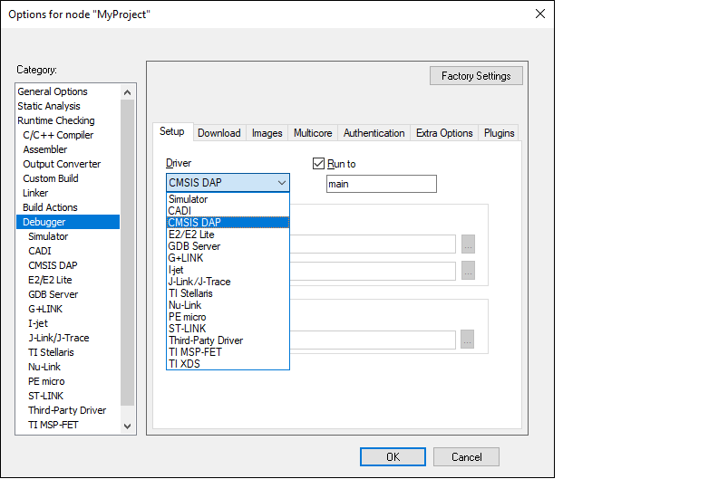
- In IAR Embedded Workbench, open the Options dialog, go to Debugger, and select CMSIS-DAP in
the driver list:
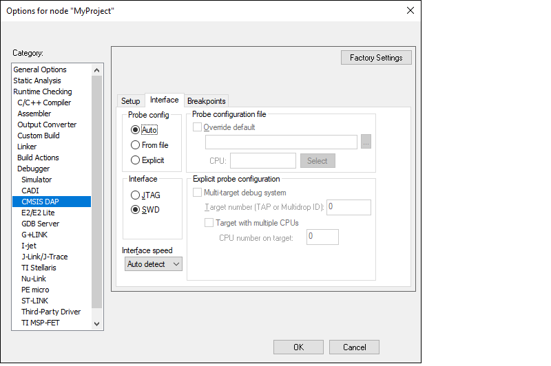
- Select the CMSIS-DAP node,
switch the interface from JTAG to SWD, and set the Interface speed to 2MHZ.
 Note:When using MiniProg4 with a single-core PSOC™ 6 MCU, you must specify a special type of Reset under the Setup tab, as follows: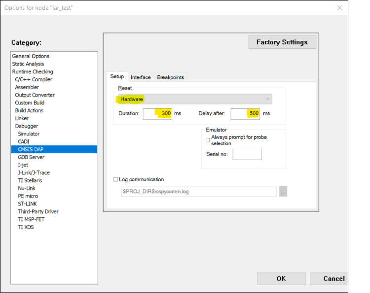
- Click OK.
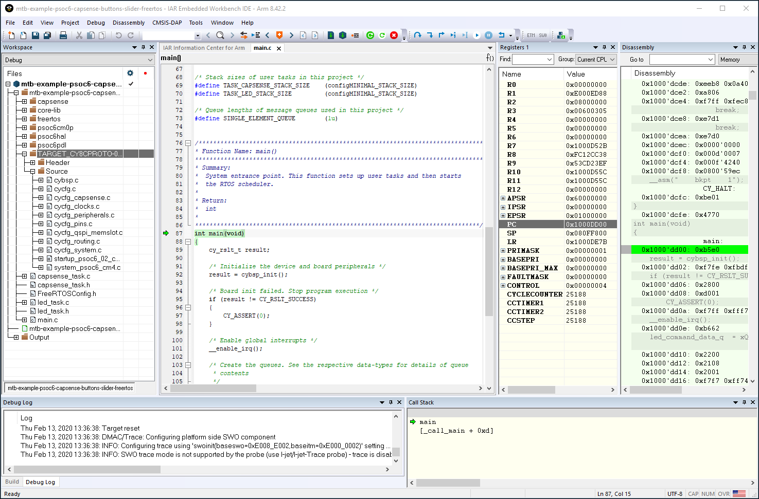
- Select Project > Download and
Debug.The IAR Embedded Workbench starts a debugging session and jumps to the main function.
Program/Debug with J-Link
You can use a J-Link debugger probe to debug the application.
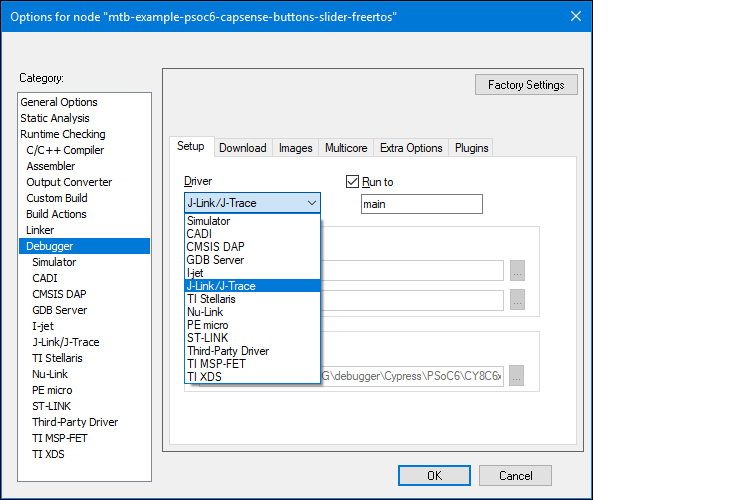
- Open the Options dialog and select the Debugger item under Category.
- Then select J-Link/J-Trace as the
active driver:
- Select the J-Link/J-Trace item
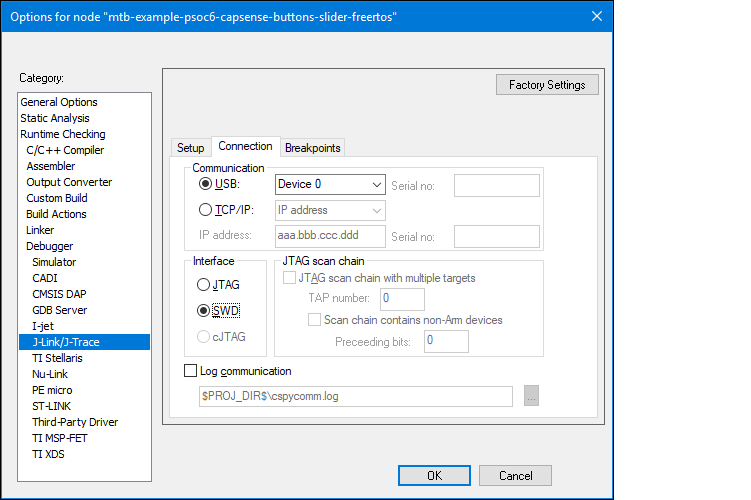
under Category, and under the Connection tab, switch the interface to SWD:
- Connect a J-Link debug probe to the 10-pin adapter (this needs to be
soldered on the prototyping kits).
- Select Project > Download and Debug to launch the debugger.
Program external memory
IAR Embedded Workbench has disabled external memory programming by default. The SMIF region in the *.board file must be enabled manually for PSOC™ 6 devices. To do that:
- Open the Options dialog and select the Debugger item under Category.
- Click the Download tab and select
the Override default .board file check box.
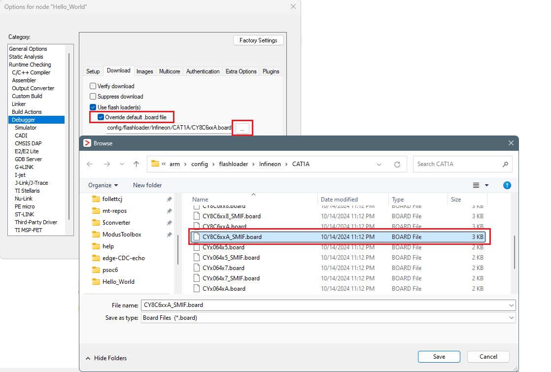
- Identify the default .board file currently used for this project.
- Click the Browse […] button, then navigate to and select the same .board file that also includes "SMIF".
- Click Save.
- Click OK to close the Options dialog.
Erase PSOC™ 6 MCU with external memory enabled
To successfully erase external memory using flashloaders on PSOC™ 6 MCUs, the device's internal flash must contain valid QSPI configuration data. It may be part of a previously programmed application, such as the QSPI_XIP example. For more details, review section 7 of application note AN228740.
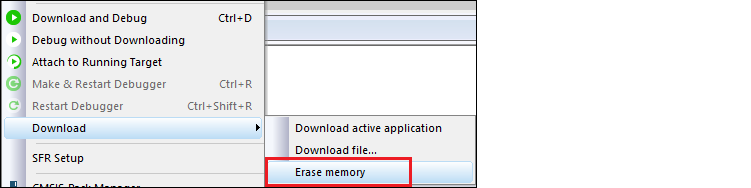
- Select Project > Download > Erase
memory.
- Deselect the check boxes for all regions, except for
0x18000000-0x1fffffff.
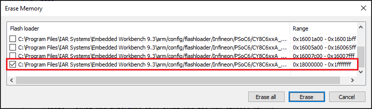
- Click Erase.
- Select Project > Download > Erase
memory again.
- Select all other regions and deselect 0x18000000-0x1fffffff.
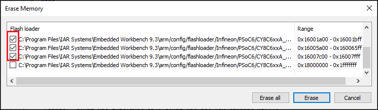
- Click Erase.