Program and debug
Programming and debugging are native to your chosen development environment. Infineon devices are supported in the major program and development solutions. Primarily, this means J-Link and OpenOCD. These solutions provide for programming flash within a device and provide a GDB server for debugging.
This chapter covers various topics related to building and debugging, including:
PSOC™ MCU programming/debugging
Launch configurations
Debug connection options
KitProg Firmware Loader
Supplying power with KitProg3_MiniProg4
Power cycle programming mode with KitProg3_MiniProg4
Switch to J-Link programmer/debugger
Using JTAG interface in MiniProg4
Changing programming interface SWD/JTAG
Erasing external memory
Programming eFuse
Select specific CMSIS-DAP device
Select Specific J-Link Device
PSOC™ 4 flash security programming
Debugging/programming for secure configuration devices
AIROC™ Bluetooth® programming/debugging
PSOC™ MCU programming/debugging
Launch configurations
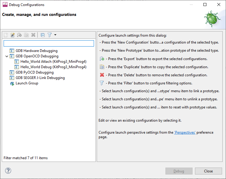
The flow for programming and debugging is similar for all devices. Eclipse contains several Launch Configurations that control various settings for programming the devices and launching the debugger. Depending on the kit and type of applications you are using, there are various Launch Configurations available.
There are two sets of configurations: one for KitProg3_MiniProg4 (included on-board on most Infineon PSOC™ 6 and PSOC™ 4 based kits) and another for SEGGER J-Link.
Note:
The KitProg3_MiniProg4 launch configuration also supports the MiniProg4, which you attach to the kit via a 10-pin debug connection. See the
MiniProg4 product page
for details. The MiniProg3 is not supported. See also
Supplying power with KitProg3_MiniProg4
later in this document for configuration requirements.
The Debug/Attach Launch Configurations are shown in the Run/Debug Configurations dialog, similar to the following.
In addition to the Debug and Attach Launch Configurations, Program/Erase configurations are available in the External Tools Configurations dialog. You can open this dialog from the
Run
menu or by selecting the down arrow next to the
Run
and
Debug
commands.
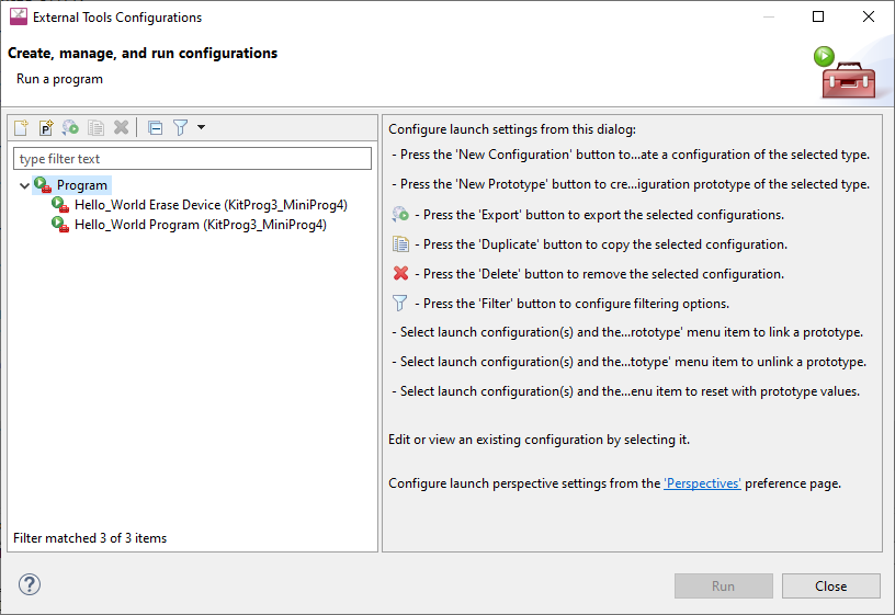
These configurations include the application name and protocol, for example:
Hello_World Program (KitProg3_MiniProg4)
Hello_World Debug (JLink) For more information, see
Debug connection options
.
Note:
KitProg3_MiniProg4 configurations may not work if a J-Link probe is attached to the kit.
When an application is created, the tool generates the following launch configurations for KitProg3 by default. You can edit the Makefile to create configurations for J-Link instead. See
Specify probe and generate launch configs
for further details. Some items display in the Quick Panel, and some are in the Run/Debug Configurations or External Tools Configurations dialogs only.
Attach : This launch configuration starts a debugging session attaching to a running target without programming or reset.
Debug : This launch configuration builds the associated project, programs the project-specific output file, and then starts a debugging session.
Erase Device : This launch configuration erases all internal memories.
Erase All :If present, this launch configuration erases all internal and external memories.
Program : This launch configuration builds the associated project, programs the project-specific output file, and then runs the program.
Debug connection options
A typical PSOC™ 6 application created for Eclipse may have launch configurations set up for one of two probes: Infineon KitProg3 (built into Infineon kits) or Segger J-Link.
KitProg Firmware Loader
The PSOC™ MCU kits include onboard programmer/debug firmware, called KitProg. The CY8CPROTO-062-4343W kit has KitProg3 by default. However, the CY8CKIT-062-BLE and CY8CKIT-062-WIFI-BT kits come with KitProg2 firmware installed, which does not work with the ModusToolbox™ software.
You must update to KitProg3
. KitProg3 provides the CMSIS-DAP (Bulk) protocol by default, which is up to ~2.5 times faster than the CMSIS-DAP (HID) protocol. Both modes can be used via OpenOCD.
To update it, use the ModusToolbox™ Programmer GUI or the fw-loader CLI tool. Both are provided with the ModusToolbox™ Programming tools package available from the
Setup program
.
For more details about these tools, refer to the
ModusToolbox™ Programmer GUI user guide
or the
Firmware Loader user guide
.
Note:
On a Linux machine, you must run the udev_rules\install_rules.sh script before the first run of the fw-loader.
Supplying power with KitProg3_MiniProg4
If using the KitProg3 connector on a kit, power is generally supplied by the host PC. When using a MiniProg4, power is not supplied via the MiniProg4 by default. It is expected that the target MCU will be powered externally. However, the MiniProg4 does provide the ability to supply power to the target MCU.
Note:
Verify the voltage range supported by the target MCU, since it can be damaged by supplying unsupported voltage. Make sure that your MCU is not powered externally before supplying power via the KitProg3_MiniProg4 launch configuration. This supply is limited to approximately 200 mA, and is protected against excess current draw. You can select 1.8 V, 2.5 V, 3.3 V, or 5 V.
Turning power supply on
To turn power supply on, edit the Debug/Attach Launch configurations:
Open the Launch Configuration to modify, and select the
Debugger
tab.
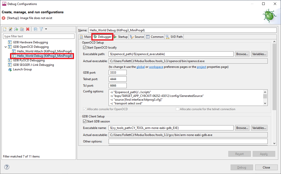
In the
Config options
field, insert the following line (after -c "source [find interface/kitprog3.cfg]"):
-c "set ENABLE_POWER_SUPPLY <mV>"Where
<mV>
defines target voltage in millivolts. For example:
Click
Apply
to save the change.
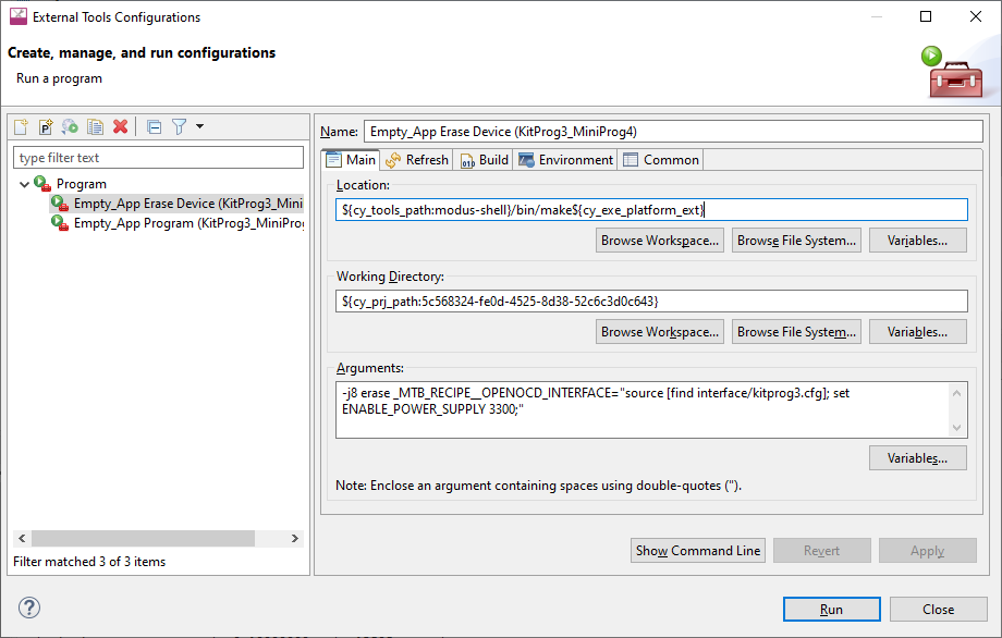
And for the Program/Erase Launch configurations:
Open the External Tools Configuration to modify in External Tools Configurations dialog.
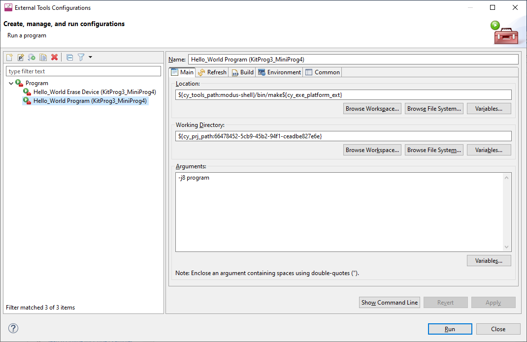
In the Arguments field, add the following:
_MTB_RECIPE__OPENOCD_INTERFACE="source [find interface/kitprog3.cfg]; set ENABLE_POWER_SUPPLY <mV>;"
Where
<mV>
defines target voltage in millivolts. For example:
Power cycle programming mode with KitProg3_MiniProg4
Note:
This section is applicable to PSOC™ 6 and PSOC™ 4 only.
By default, Launch Configurations use Reset mode to program the device. However, Reset mode is not available in all situations (for example, if the XRES pin is not available on the part's package). In these cases, Launch Configurations use an alternative reset using software. However, using the software reset type is not sufficient in some cases when access to the device's DAP is restricted (such as when set by security settings).
If there is no XRES pin available and DAP access is restricted, the only way to reset a part is to use Power Cycle mode. Follow these instructions to add commands to the launch configuration and switch to Power Cycle mode.
Note:
Verify the voltage range supported by the target MCU, since it can be damaged by supplying unsupported voltage. Make sure that your MCU is not powered externally before supplying power via the KitProg3_MiniProg4.
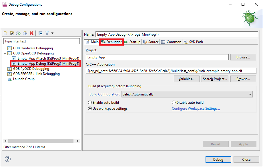
To update Debug Launch configurations:
Open the Launch Configuration to modify and select the
Debugger
tab.
In the
Config options
field, insert the following lines(after
-c "source [find interface/kitprog3.cfg]"
) :
For PSOC™ 6:
-c "set ENABLE_POWER_SUPPLY <mV>"
-c "set ENABLE_ACQUIRE 2"
For PSOC™ 4:
-c "set ENABLE_POWER_SUPPLY <mV>"
-c "set PSOC4_USE_ACQUIRE 2"
Where
<mV>
defines target voltage in millivolts. For example:
And for Program/Erase Launch configurations:
Open the External Tools Configuration to modify, then select the
Main
tab.
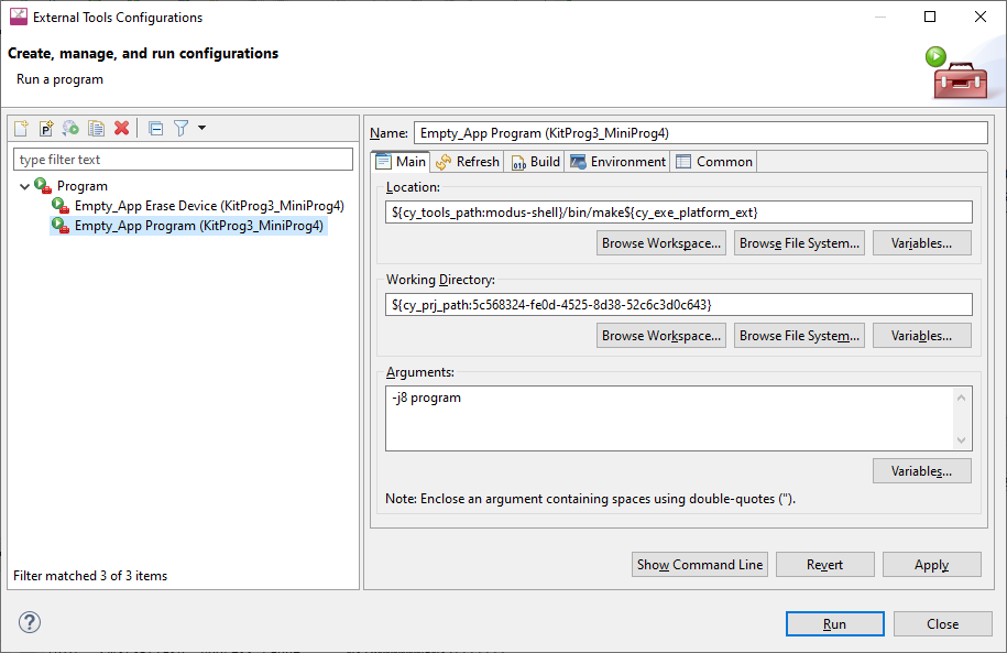
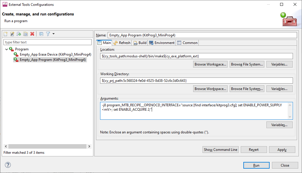
In the
Arguments
field add the following:
For PSOC™ 6:
_MTB_RECIPE__OPENOCD_INTERFACE="source [find interface/kitprog3.cfg]; set ENABLE_POWER_SUPPLY <mV>; set ENABLE_ACQUIRE 2;"
For PSOC™ 4:
_MTB_RECIPE__OPENOCD_INTERFACE="source [find interface/kitprog3.cfg]; set ENABLE_POWER_SUPPLY <mV>; set PSOC4_USE_ACQUIRE 2;"
Where
<mV>
defines target voltage in millivolts. For example:
Using JTAG interface in MiniProg4
The MiniProg4 can interact with the target via the SWD or JTAG protocol. By default, the SWD protocol will be used.
In order to use JTAG, you need to add specific commands for the appropriate Debug Configuration. Under the
Debugger
tab in the
Config options
field (after
-c "source [find interface/kitprog3.cfg]"
), insert the following lines:
-c "cmsis_dap_vid_pid 0x04B4 0xF151 0x04B4 0xF152"
-c "transport select jtag"

Changing programming interface SWD/JTAG
Usually MCUs support programming/debugging via SWD and JTAG interfaces. The SWD interface is the default, but you can switch to JTAG, and vice-versa.
To change target interface, update application’s bsp.mk by adding make variable as shown below (possible values are ‘swd’ and ‘jtag’) and regenerate launch configurations:
MTB_PROBE_INTERFACE=swd
Note:
There might be a difference in how the MCU functions depending on the selected debugging interface. All known issues are documented in Release Notes.
Single-core projects
Kitprog3/MiniProg4
To change the target interface for KitProg3_MiniProg4, do the following:
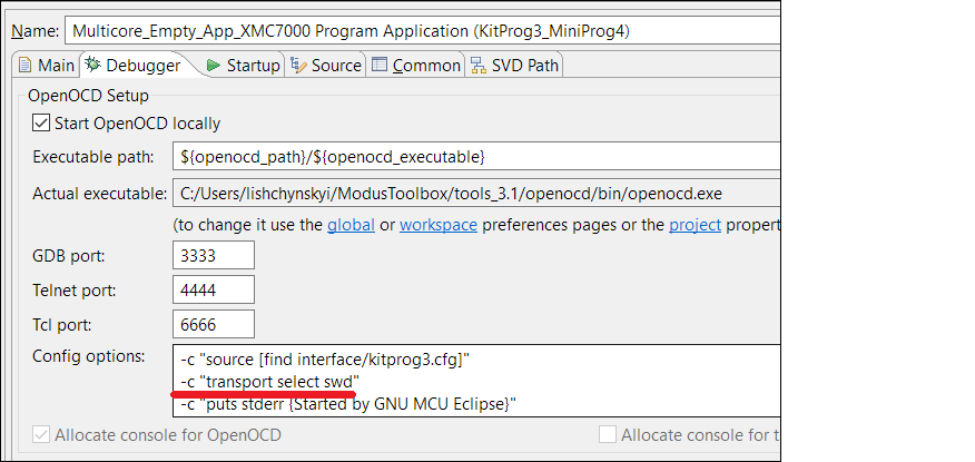
Open the Debug Configurations dialog and select the required configuration.
Switch to the
Debugger
tab and find the "transport select ..." entry in
Config options
.
Set to the value to either 'swd' or 'jtag' as applicable.
J-Link
For J-Link, there is a dedicated radio button in the Debug Configurations dialog, under the
Debugger
tab. Select the applicable option:

Multi-core projects
There is a special case for multi-core debugging. This is usually launched via the 'Debug MultiCore' configuration. To switch from one interface to another, the same interface must be set across all involved configurations. The Debug Configurations dialog shows the list of configurations that are launched as a part of multi-core debugging.

Erasing external memory
To erase external memory use the Erase All configuration:
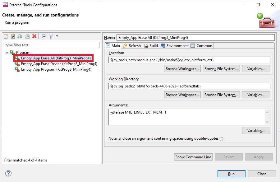
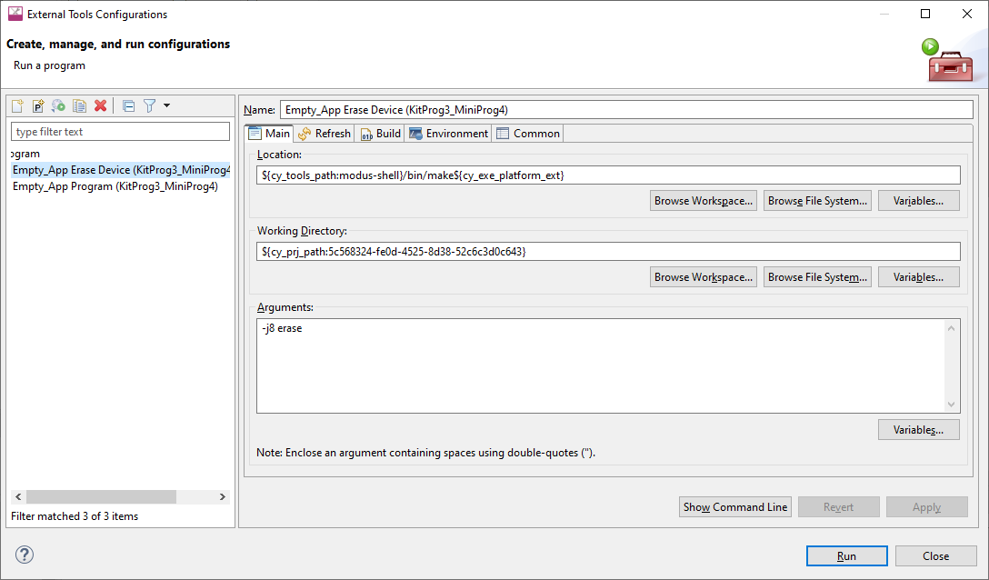
However, for PSOC™ 6 and PSOC™ 64 Secure Boot kits by default, erasing of external memory is turned off. To turn it on, you must modify the "Erase" launch configuration options in the External Tools Configuration as follows:
Open the External Tools Configuration to modify, and select the
Main
tab.
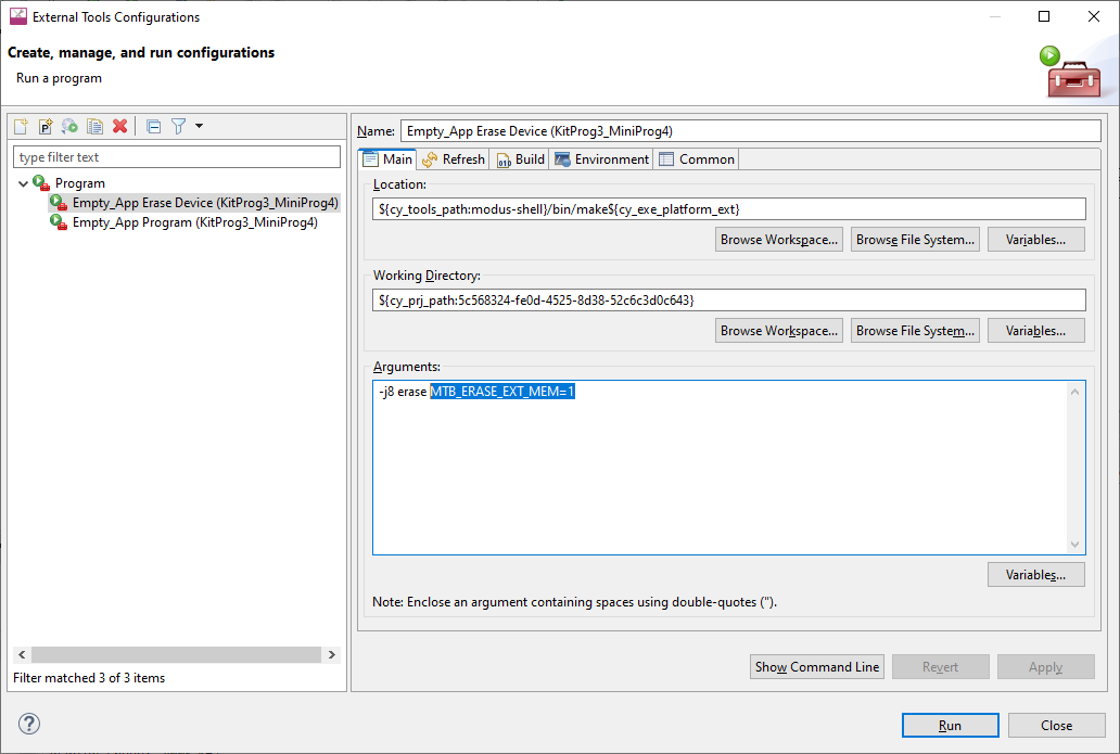
In the Arguments field add the following:
MTB_ERASE_EXT_MEM=1
Programming eFuse
PSOC™ 6 MCUs contain electronic fuses (eFuses), which are one-time programmable. They store device specific information, protection settings and customer data.
By default, eFuses are not programmed even if they are present in the programming file. To enable eFuse programming, add the following command for the Program Configuration, under the
Main
tab in the
Arguments
field (after
-j8 program
):
"_MTB_RECIPE__OPENOCD_TARGET=source [find target/$(_MTB_RECIPE__OPENOCD_DEVICE_CFG)]; psoc6 allow_efuse_program on;"
Attention:
Since blowing an eFuse is an irreversible process, Infineon recommends programming only in mass production programming under controlled factory conditions and not prototyping stages. Programming fuses requires the associated I/O supply to be at a specific level: the device VDDIO0 (or VDDIO if only one VDDIO is present in the package) supply should be set to 2.5 V (±5%).
Select specific CMSIS-DAP device
If there are two or more CMSIS-DAP devices connected to your computer, the first detected device will be used by default. KitProg3 supports both CMSIS-DAP modes: HID and BULK. BULK devices are selected first, then HID devices. You can specify a CMSIS-DAP device by:
VID and PID of the USB device
Serial Number of the USB device
VID, PID, and Serial Number of the USB device
There are two ways of specifying a CMSIS-DAP device:
Add a specific command for the appropriate Debug Configuration, under the
Debugger
tab in the
Config options
field (after
-c "source [find interface/kitprog3.cfg]"

Modify ModusToolbox™ application's bsp.mk by adding a
MTB_PROBE_SERIAL
variable, and regenerate launch configurations
Selecting by VID and PID
Use OS-specific tools to determine the VID and PID of connected devices. For example, on Windows, use the Device Manager. Use the "cmsis_dap_vid_pid" command to select a CMSIS-DAP device with a specific VID and PID. If there are two or more devices with the same specified VID/PID pair, OpenOCD uses the first detected device from the passed list.
To specify KitProg3 in CMSIS-DAP BULK mode with VID = 0x04B4 and PID = 0xF155:
cmsis_dap_vid_pid 0x04B4 0xF155
To specify KitProg3 in CMSIS-DAP HID mode with VID = 0x04B4 and PID = 0xF154:
cmsis_dap_vid_pid 0x04B4 0xF154
To specify any (HID or BULK) connected KitProg3 device:
cmsis_dap_vid_pid 0x04B4 0xF154 0x04B4 0xF155
Selecting by serial number
There should not be more than one device with the same serial number. Use this method if you want to use only one specific device. Use OS-specific tools to determine the Serial Number of connected devices. You can also use the fw-loader utility with
--device-list
option. See
PSOC™ 4 flash security programming
.
Use the "cmsis_dap_serial" command to select a CMSIS-DAP device with a specific Serial Number.
To specify a CMSIS-DAP device with Serial Number = 0B0B0F9701047400 via Debug Configuration the following command is used:
-c "adapter serial 0B0B0F9701047400"Alternatively, update the application's bsp.mk by adding the variable below, and regenerate launch configurations:
MTB_PROBE_SERIAL=0B0B0F9701047400
Selecting by both VID/PID and serial number
You can use both commands together in any order directly in Debug Configuration. For example:
cmsis_dap_vid_pid 04B4 F155 cmsis_dap_serial 0B0B0F9701047400
When updating through an application's bsp.mk, add the variable below, and regenerate launch configurations:
MTB_PROBE_SERIAL=0B0B0F9701047400; cmsis_dap_vid_pid 04B4 F155;
Select Specific J-Link Device
If there are two or more J-Link devices connected to your computer, the first detected device is used by default. You can select a specific J-link device by setting the serial number for the appropriate Debug Configuration, under the
Debugger
tab:

Alternatively, update the application's bsp.mk by adding the variable below, and regenerate launch configurations:
MTB_PROBE_SERIAL=0B0B0F9701047400
PSOC™ 4 flash security programming
PSOC™ 4 devices include a flexible flash-protection system that controls access to flash memory. This feature secures proprietary code, but it can also be used to protect against inadvertent writes to the bootloader portion of flash. Refer to the device’s Architecture Technical Reference Manual for details.
Flash consists of rows (64/128/256 bytes, depending on the PSOC™ 4 device). Each row of flash can have its protection level independently set. You can assign one of two protection levels to each row, as shown in the following table:
Protection Setting | Allowed | Not Allowed |
|---|---|---|
Unprotected | External read and write, Internal read and write | – |
Full Protection | External read, Internal read | External write, Internal write |
To apply flash security, include the appropriate data in the application by creating an array of num_rows / 8 size, where num_rows is the actual number of flash rows on the device. Each byte of this array is responsible for protection of 8 flash rows, and it sets one of two protection levels:
0 – unprotected
1 – full protection
For example, to protect the first 25 rows and the last 5 out of 256 rows, include the following array in your application:
CY_SECTION(".cyflashprotect") __USED
static const unsigned char flash_protect[0x20] =
{
  0xFF, 0xFF, 0xFF, 0x01, 0x00, 0x00, 0x00, 0x00, 0x00, 0x00, 0x00, 0x00, 0x00, 0x00, 0x00, 0x00,
  0x00, 0x00, 0x00, 0x00, 0x00, 0x00, 0x00, 0x00, 0x00, 0x00, 0x00, 0x00, 0x00, 0x00, 0x00, 0x00
};
To enable flash security, program the device with the updated code. If you wish to reprogram a protected device, you must first erase it.
Debugging/programming for secure configuration devices
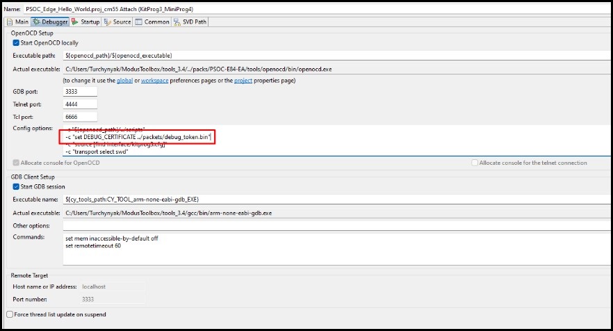
The BootROM on devices such as PSOC™ Control and PSOC™ Edge can temporarily disable access to the core's Access Port(AP). This behavior is determined by the security policy during device provisioning. However, access can be re-enabled using a debug certificate. If a debugger identifies that the AP is disabled, it will upload and verify the debug certificate found in the
"./packets/debug_token.bin"
file within the current project folder.
Single-core Projects
By default, the debug certificate must be located in
./packets/debug_token.bin
in the root of the project for both OpenOCD and Segger J-Link.
OpenOCD
You can change the path and address of the debug certificate using the following command:
-c "set DEBUG_CERTIFICATE %PATH_TO_TOKEN%"
-c "set DEBUG_CERTIFICATE_ADDR %HEX_ADDRESS%"
J-Link
Note:
It is important to recognize that neither the name of the certificate file or its location can be changed.
The debug certificate must be located in the root of the project/application.
Multi-core Projects
OpenOCD
As with single-core projects, you can change the path and address of the debug certificate using the following command:
-c "set DEBUG_CERTIFICATE %PATH_TO_TOKEN%"
-c "set DEBUG_CERTIFICATE_ADDR %HEX_ADDRESS%"
J-Link
Note:
Always remember to locate ./packets/debug_token in the root of each application's core (sub-project).
It is important to recognize that neither the name of the certificate file or its location can be changed.
Multi-core debug CM33 secure application booting from RRAM
When using multi-core debug CM33 secure applications booting from RRAM (for example PSOC_Edge_RTC_periodic_wakeup), you must configure the launch configuration to add the SMIF IP enabling commands.
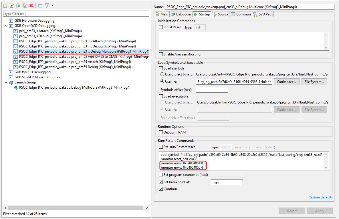
Add the following under the
Startup
tab under
Run/Restart Commands
:
For KitProg3/MiniProg4
monitor mww 0x54004054 0
monitor mww 0x54004050 4
For J-Link
monitor memU32 0x54004054=0
monitor memU32 0x54004050=4
AIROC™ Bluetooth® programming/debugging
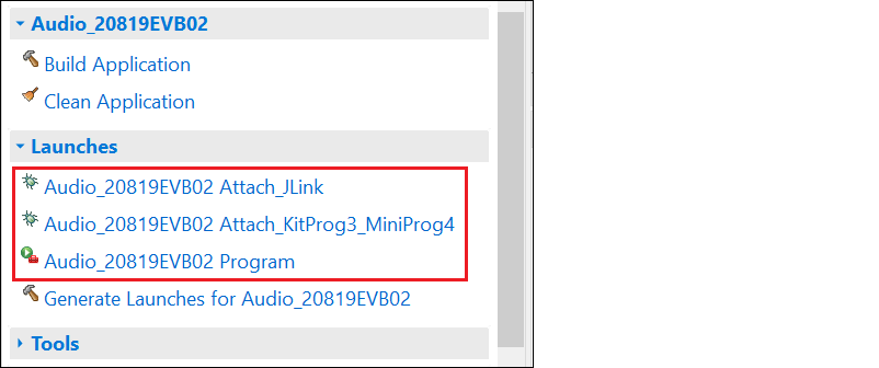
AIROC™ Bluetooth® applications have different launch configurations than PSOC™ MCU applications. Bluetooth® applications use External Tools configurations for programming the device, and Attach configurations for attaching to the debugger. The Program launch configurations are available from the Quick Panel when you select <app name> project. Each configuration is preceded by the application name.
Program configuration
This launch configuration runs a script and programs the device's memories.
<app-name> Program
: Program is used to build and program embedded applications onto the target device.
Attach configurations
The Attach configurations are used to attach to the debugger without first programming the device. They include:
<app-name> Attach_JLink
<app-name> Attach_KitProg3_MiniProg4
Debug settings
AIROC™ Bluetooth® devices use the JTAG SWD interface on a kit for debug via OpenOCD or J-Link probe. Typically, GPIOs need to be reprogrammed (via firmware) to enable SWD, so debug can't be performed directly after a device reset. The debugger is usually attached to a running device and symbols only are loaded.
The CYW920819EVB-02 and CYBT-213043-MESH kits have additional requirements in order to launch Eclipse debugger. In general, most debugging for these kits is done with logs and sniffers, since real time execution is usually needed for the protocols to run properly.
Refer to the
AIROC™ Hardware Debugging document
for more details.