Quick start
This section provides a simple workflow for how to use the Segment LCD Configurator.
Launch the Segment LCD Configurator
from the Device Configurator.
On the Segment LCD Configurator toolbar, click the
Edit Displays

button to open the
Display Editor
dialog.
On the Display Editor dialog toolbar, click the
Add New Display
button. In the new row, select the
Type
and specify the display
Name
and number of
Symbols
.
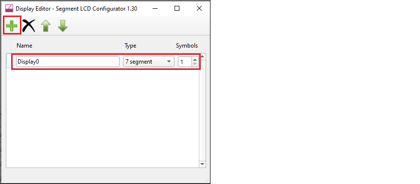
Close the dialog by clicking the
X
button or pressing [
Esc
].
On the Segment LCD Configurator toolbar, specify the number of
Common
and
Segment
LCD connections corresponding to the mapping table dimensions. See the
Mapping table
section for more information.
On the Display view, left-click and hold a pixel of the symbol, drag it onto the mapping table below the Display view, and release the mouse button on the desired cell.
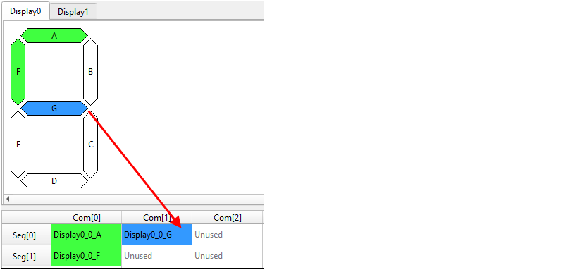
Repeat this process for all display pixels.
Save the configuration and close the Segment LCD Configurator.
Back on the Device Configurator, there are several tasks in the Notice List, which correlate to the number of Common and Segment signals you configured.
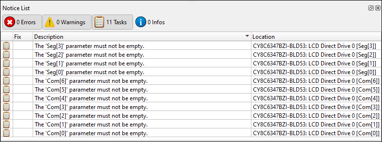
Double-click one of the task icons to jump to the Parameters pane for the corresponding connection parameter. Click the pull-down menu and select the appropriate signal.
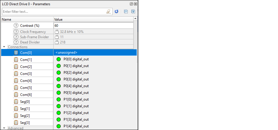
Repeat the process for every task.
When finished, save and close the Device Configurator; see
Code generation
.