ADC tab
The
ADC
tab provides the options to configure ADC channels and protection settings in the respective parts.
Toolbar
The
ADC
tab toolbar contains
Add
and
Remove
channel buttons. The
Remove
button is active only for the last channel on the list.
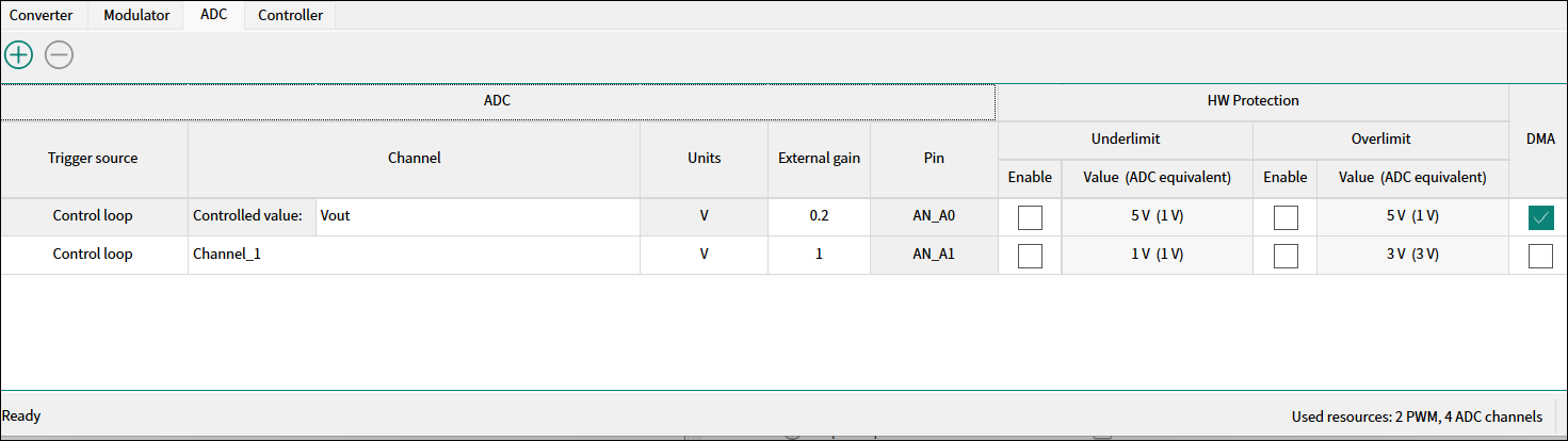
ADC channels table
ADC
Triggered source
– The ISR trigger priority. The options from the dropdown menu:
Control loop
or
Scheduled
. For details, see the middleware documentation:
Channel
– The channel name is auto-set or custom. The first channel configuration is mandatory for the
Infineon control loop
. The controlled output parameter –
Vout
, and the channel name is defined accordingly
Units
– The units of the respective channel. You can select from the dropdown menu:
V
(volts),
A
(amperes),
º
(degrees), or
Custom
.
External gain
– The resulting factor of the signal conditioning on the electrical quantity: either attenuation or amplification. The value range is 0.001 - 100.
Pin
– Displays the pin assigned to the channel. The pin assignment can be changed from the Device Configurator
HW Protection
Underlimit/Overlimit
– The protection from the under/over crossing ADC range. Check a corresponding check box to enable bottom/top boundary protection.
Value (ADC equivalent)
– Represents the voltage of the native electrical quantity at the MCU pin after conditioning. The maximum supported ADC value is 3.3 V and the minimum – 0V.
DMA
Enables the HW DMA transfer from the ADC register to SRAM memory. Check this box for the selected channel. This option is available if the triggered source is the control loop.