Converter tab
The
Converter
tab performs configuration of the general converter parameters.

Control mode
There are two control modes for the buck converter to regulate the output voltage:
Voltage
– Regulates the output voltage by using only the output voltage itself.
Peak Current
– Regulates the output voltage by using the output voltage and high-side switch current as control parameters.
Schematic diagram parameters
Click the green items on the schematic diagram to edit correspondent parameters: Vin (42V), L (33µH), Iout 2A, Vout (12V), C(118µF).
Input voltage (Vin)
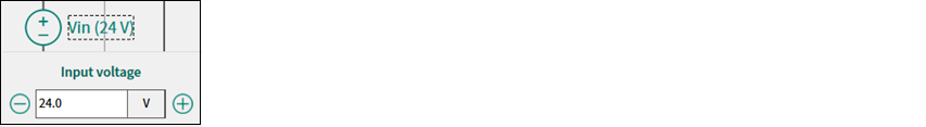
Parameter | Description | Range | Default |
|---|---|---|---|
Input voltage | Converter input voltage | 9-800 V | 24 V |
Output voltage (Vout)
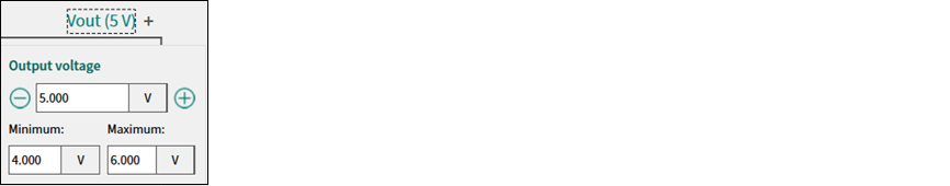
Parameter | Description | Range | Default |
|---|---|---|---|
Output voltage | Target converter output voltage | 2.5-240 V | 5 V |
Minimum | Minimum possible value of converter output voltage | 2.5-240 V | 4 V |
Maximum | Maximum possible value of converter output voltage | 2.5-240 V | 6 V |
Output current (Iout)

Parameter | Description | Range | Default |
|---|---|---|---|
Output current | Target converter output current | 0.1-10 A | 2 A |
Inductance (L)

Parameter | Description | Range | Default |
|---|---|---|---|
Inductance | Inductance value | 0.1 - 1000000 µH | 33.0 µH |
ESR | Equivalent series resistance of inductor | 0.1 - 1000000 mΩ | 30 mΩ |
Capacitance (C)

Parameter | Description | Range | Default |
|---|---|---|---|
Capacitance | Capacitance value | 0.1 - 1000000 µF | 118 µF |
ESR | Equivalent series resistance of capacitor | 0.1 - 1000000 mΩ | 25 mΩ |
Sensor

The sensor parameters are available only in PCCM.
Parameter | Description | Range | Default |
|---|---|---|---|
Current sense gain | Equivalent transducer gain to transform current to voltage (e.g. shunt resistance in ohms) | 0.001 - 100 V/A | 1 V/A |
Control parameters
The
Control parameters
group provides options to enter the required values.
Parameter | Description | Range | Default |
|---|---|---|---|
Number of phases | Number of converter's interleaving phases | 1 - 4 | 1 |
Switching freq | Target switching frequency of power switch operation | 50000 - 1000000Hz | 300000Hz |
Control loop divider | Fast control loop frequency divider | 1 - 5 | 1 |
Time delay | Time expressed in fraction of PWM period to account for the inherent delay introduced by digital implementation: from analog sensing to duty cycle update. Such a delay is taken into account in the phase margin determination. | 0 - 10.0 | 2.00Ts |
Control loop freq | Converter sampling frequency | 10000 - 1000000Hz | 300000Hz |
Crossover freq* | Target crossover frequency | 2000 - 200000 Hz | 10000 Hz |
Phase margin* | Target phase margin | 10 - 90 | 50 |
Note:
*The calculated valid range for theCrossover frequencyand maximum valid value forPhase margindepend on the set of entered parameters. They display in the respective parameter tooltip.
Compensation settings (poles and zeros)
The
Compensation settings (poles and zeros)
are the characteristic of the transfer function of the converter's control system. They can be either calculated automatically or set manually. The compensator type may be Type III (VCM) or Type II (PCCM). The number of poles and zeros aligns correspondingly with the selected Control mode.
Parameter | Range | Default |
|---|---|---|
Pole at origin (Hz) | 0 - 1e+09 | 487.841 |
Pole 1 (Hz) | 0 - 1e+09 | 4822.877 |
Pole 2 (Hz) (VCM only) | 0 - 1e+09 | 100000.000 |
Zero 1 (Hz) | 0 - 1e+09 | 916.445 |
Zero 2 (Hz) (VCM only) | 0 - 1e+09 | 2250.091 |
Copy values
– Click this button to copy the compensation settings values.
You can use them in your custom code example for
VCM
:
#define Pole0 487.841
#define Pole1 4822.877
#define Pole2 100000.000
#define Zero1 916.445
#define Zero2 2250.091
or
PCCM
:
#define Pole0 24659.727
#define Pole1 4822.877
#define Zero1 882.364