Modulator tab
The
Modulator
tab defines the configuration for high-level parameters of PWM instances.
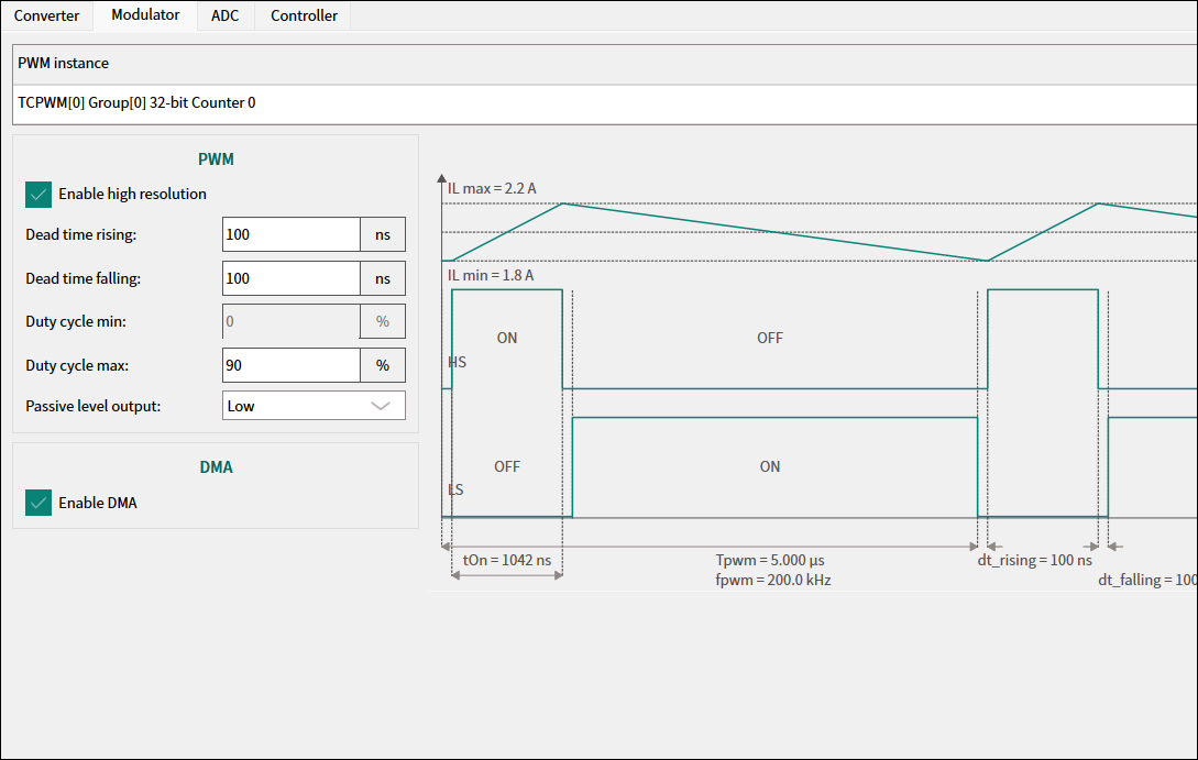
Modulator tab in Voltage Control Mode
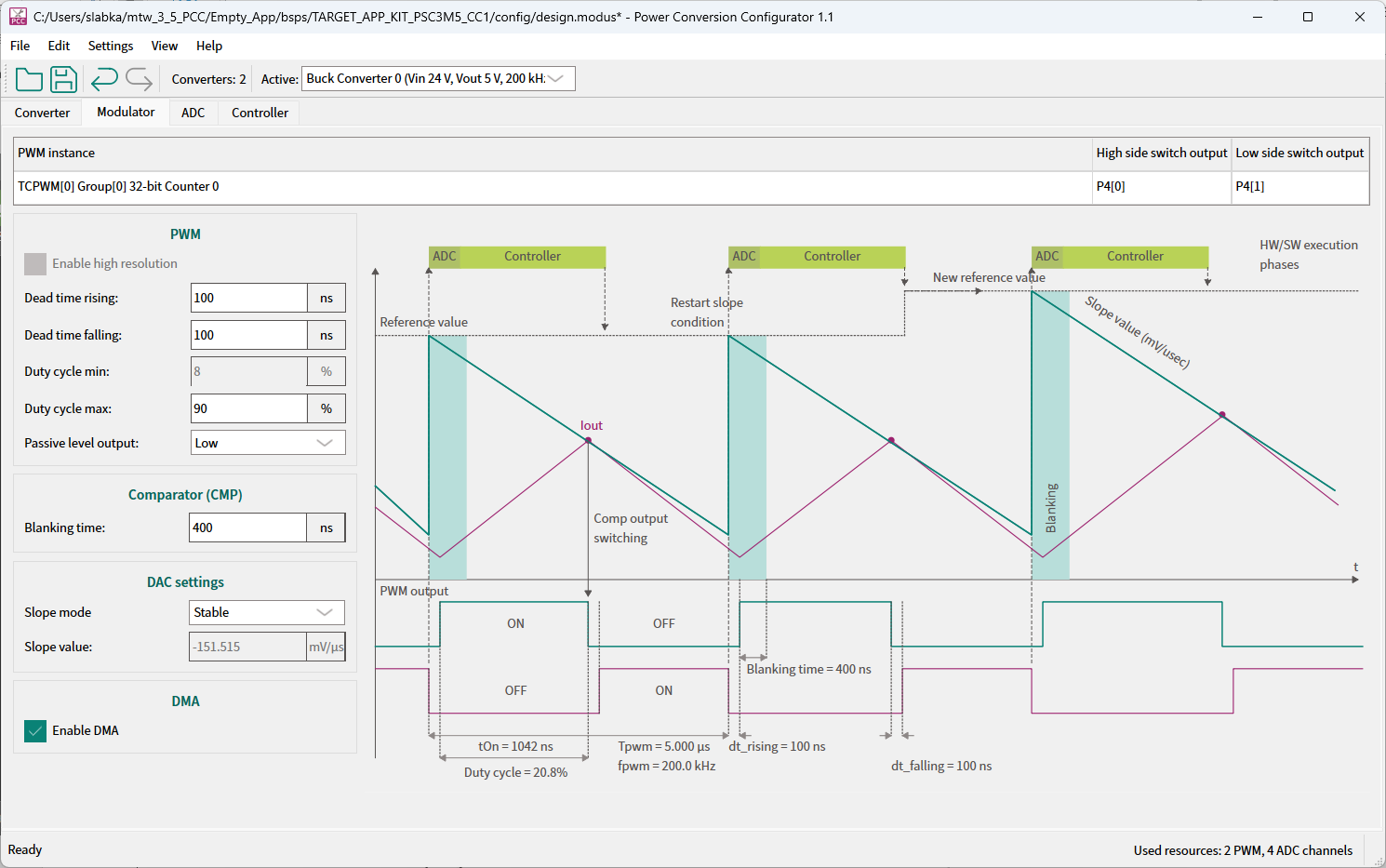
Modulator tab in Peak Current Control Mode
PWM instance table
The
PWM instance
table displays information about allocated PWM resources.
High/Low side switch output
Corresponding pins assigned to the output.
PWM
Enable high resolution
– This check box is active only for VCM.
The PWM group settings parameters are applied to all PWM instances.
Parameter | Description | Range | Default |
|---|---|---|---|
Dead time rising | Dead time delay for HS | 1-1e+09 ns | 100 ns |
Dead time falling | Dead time delay for LS | 1-1e+09 ns | 100 ns |
Duty cycle min | Minimum modulation duty cycle | Read-only | 0% |
Duty cycle max* | Maximum modulation duty cycle | 1-100% | 90% |
Passive level output | Behavior of PWM outputs with passive PWM | Low High High impedance | High impedance |
Note:
*The calculated valid range forDuty cycle maximumdepends on the entered set of parameters. They display in the respective parameter tooltip.
Comparator (CMP)
The
Comparator (CMP)
is available only in
PCCM
.
Parameter | Description | Range | Default |
|---|---|---|---|
Blanking time | The time period when input is ignored to avoid switching transient | 0-1000 ns | 200 ns |
DAC settings
The
DAC settings
group is available only in
PCCM
.
Parameter | Description | Range | Default |
|---|---|---|---|
Slope mode | Added by DAC current compensation slope | Stable (HW-based) Responsive (HW-based) Custom (editable) | Stable |
Slope value | The decrease rate of the comparator reference voltage; active in custom Slope mode | -3300-0 mV/µs | -151.515 mV/µsec |
DMA
Enable transfer DMA
– This check box is active for VCM and PCCM.
The DMA is used to transfer the modulation value stored in the
mtb__stc_pwrconv_ctx_t.mod
structure to the modulator registers, which are PWM or DAC buffers.
PWM diagram
The diagram on the right side illustrates the control loop operation replotted for VCM and PCCM. At the bottom, the dynamically-replotted PWM ON/OFF scheme for the HS and LS (high/low side) switches depending on the time scale with marked PWM period, Duty cycle, and dead times. The time change of the inductance current is on the top of the scheme. In PCCM, the slope generator curve, ADC and Controller blocks present the control loop operation.