Tuner communication setup
The "Tuner Communication Setup" dialog is used to establish communication between the Tuner and target device. The Tuner supports I2C, UART, and RTT communication interfaces.
Select
Tools > Tuner Communication Setup…
on the menu to open the dialog or click the
Tuner Communication Setup
button. The dialog opens automatically after clicking the
Connect
button if no device was previously selected.
Select the device and communication interface by checking the item with the interface name. Change the interface configuration parameters to match the configuration of the communication peripheral in the application.
Note:
The parameters in the "Tuner Communication Setup" dialog must be identical to the parameters of the EZI2C or UART driver in the application.
I2C
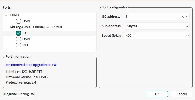
To establish the
I2C
communication between the Tuner and target device, configure the Tuner communication parameters to match the parameters of the device EzI2C settings.
The I2C communication can work in the two Read modes (see Main toolbar).
UART
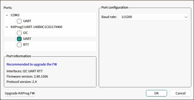
To establish the UART communication between the Tuner and target device, configure the Tuner communication parameters to match the parameters of the device UART settings.
Depending on the application capabilities, the UART communication may work in two modes: Read/Write and Read Only (see
Status bar
).
Note:
Recommended – enable the UART Flow control on the target device for bitrates equal or higher than 1000000.
RTT
The RTT is an interface specified by SEGGER based on basic memory reads and writes to transfer data bidirectionally between the target and host. Before configuring the RTT setup dialog, it is recommended to familiarize yourself with the RTT protocol fundamentals at
.
The data transfer between the host and target devices is organized through channels. The Tuner communicates to the server (OpenOCD) via the TCP/IP protocol. The server in turn uses the SWD interface to communicate with the device.
RTT communication advantages:
SWD pins are used instead of reserving EZI2C or UART pins.
The communication speed is the highest among all options.
To establish the RTT communication between the Tuner and target device, start either the local RTT server or connect to an existing one. For details on the application layer, refer to
Setting up RTT communication in application
.
Start RTT server locally
To start the RTT server in your local environment, select
Start RTT server locally
and modify the following fields:
Executable – The * .elf file generated by the firmware build. In most cases, it will be prefilled automatically based on the ModusToolbox™ project.
TCP ports range – Used for the RTT communication. Each port is mapped to a channel. Set up at least two channels because Channel 0 has limitations.
Tuner TCP port – The TCP port used by the Tuner.
OpenOCD .cfg file – Provides the * .cfg file name for OpenOCD. In most cases, it will be detected automatically based on the application target device and will not display on the GUI. If becomes visible when the * .cfg file name value cannot be detected by the Tuner automatically and must be selected manually. The * .cfg file name can be found in the .launch file of your project.
To manage the RTT server, the Tuner uses the * .rtt.tcl file located with the Tuner executable (or capsense-tuner.app/Contents/Resources/ on macOS). It starts an OpenOCD session that lasts while the Tuner is connected to the device.
Note:
Only one instance of OpenOCD can be run at a time. If you want to debug the application simultaneously, refer to RTT communication with simultaneous debug.
Connect to existing RTT server
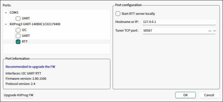
To connect to an existing RTT server, deselect
Start RTT server locally
and modify the following fields.
Hostname or IP – Specifies the host or IP address of the running RTT server.
Tuner TCP port – The TCP port used by the Tuner.
Setting up RTT communication in application
To enable the RTT communication, include the SEGGER RTT library in the application. It is a part of the J-Link Software and Documentation Pack, which is available for download on the
SEGGER official website
. The RTT library is located inside the "Samples" folder. Place it in the project root folder. Refer to the
RTT API documentation
to learn how to use it.
Add sample code to the
main.c
file:
Include a header
#include "SEGGER_RTT/RTT/SEGGER_RTT.h"Initialize RTT
SEGGER_RTT_Init();Configure the up and down buffers. Set the size of: the up buffer to at least sizeof(cy_capsense_tuner) + 5 + 1 (5 bytes for the packet header and trailer, 1 byte for internal RTT purposes); the down buffer to at least 32 bytes.
SEGGER_RTT_ConfigUpBuffer(RTT_TUNER_CHANNEL, "tuner", &tunerUpBuf, sizeof(tunerUpBuf),
SEGGER_RTT_MODE_NO_BLOCK_SKIP);
SEGGER_RTT_ConfigDownBuffer(RTT_TUNER_CHANNEL, "tuner", &tunerDownBuf, sizeof(tunerDownBuf),
SEGGER_RTT_MODE_BLOCK_IF_FIFO_FULL);
Implement the send and receive functions. Assign them to the callbacks.
Static void rtt_tuner_send(void * context);
static void rtt_tuner_receive(uint8_t ** packet, uint8_t ** tunerPacket, void * context);
...
cy_capsense_context.ptrInternalContext->ptrTunerSendCallback    = rtt_tuner_send;
cy_capsense_context.ptrInternalContext->ptrTunerReceiveCallback = rtt_tuner_receive;
...
cy_capsense_context.ptrInternalContext->ptrTunerSendCallback    = rtt_tuner_send;
cy_capsense_context.ptrInternalContext->ptrTunerReceiveCallback = rtt_tuner_receive;

...

void rtt_tuner_send(void * context)
{
    (void)context;
    /* Packet size including 2-byte header and 3-byte trailer */
    uint16_t elemCount = sizeof(cy_capsense_tuner) + 5;

    /* Lock RTT */
    SEGGER_RTT_LOCK();
    SEGGER_RTT_BUFFER_UP *buffer = _SEGGER_RTT.aUp + RTT_TUNER_CHANNEL;
    /* Copy CAPSENSE tuner structure data to the buffer */
    ...
    /* Manually update the pointers */
    buffer->RdOff = 0;
    buffer->WrOff = elemCount;

    /* Unlock RTT */
    SEGGER_RTT_UNLOCK();
}

...

void rtt_tuner_receive(uint8_t ** packet, uint8_t ** tunerPacket, void * context)
{
    while(0 != SEGGER_RTT_HasData(RTT_TUNER_CHANNEL))
    {
        uint8_t byte;
        SEGGER_RTT_Read(RTT_TUNER_CHANNEL, &byte, 1);
        ...
    }
}
The Tuner is expected to receive packets in the following format:
OD 0A <cy_capsense_tuner> 00 FF FF
OpenOCD Log pane
The Tuner offers a special OpenOCD Log view to observe OpenOCD communication logs.

RTT communication with simultaneous debug
The RTT interface allows communication with the CAPSENSE™ Tuner and debugging simultaneously over the same pair of SWD pins. The RTT communication utilizes OpenOCD. To debug simultaneously, establish a connection with the Tuner and then attach the debugger to the already running OpenOCD session. For details, refer to the debug section of your IDE user guide.
Communication and Low power mode
The Tuner requires a working communication channel (I2C, UART, RTT). While the device is operating in Low power mode, it cannot communicate with the Tuner. In order to have a stable communication, Synchronization mode was introduced between the Tuner and the device. In this mode, the Tuner controls the device, particularly the moment of starting a next scan. If this process is interrupted, communication may be lost. To avoid this, follow the recommendations:
The following are the limitations necessary for maintaining the successful connection of the Tuner with a device:
The PSOC™ side firmware ensures that after the device exits Deep Sleep mode, it stays in the active state with the working communication channel, which enables the Tuner to receive at least one packet with valid data.
The device sleeps less than the Tuner-defined timeout (see the LP command timeout in the Tuner Configuration options dialog, Advanced tab).
Implement the Deep Sleep callback, which waits for the completion of an EzI2C/UART transaction before the transition to Deep Sleep.
Also recommended:
Add
Cy_SysLib_Delay100-500 ms after the CAPSENSE™ initialization completes before the transition to Deep Sleep to give the Tuner time to exchange packets with the device.
The Tuner has the following timeouts by default:
Connect timeout: 3 sec
Read/write timeout: 250 sec.
Device power control
The Tuner offers a convenient feature to control the device power using the
Power
button, which provides the following functionalities:
Monitor the target device power
Turn the power on/off (if supported)
Control the target device voltage (if supported)
All kits with KitProg devices support the power monitoring and the target voltage displays on the Tuner status bar. However, not all devices support the powering on/off or adjusting the voltage. The power control behavior depends on the kit type as detailed below:
Kits that support power on/off without voltage
control
The Power button is enabled but the voltage selection is not available.
The value of the target voltage is determined by the board design.
Note:
KitProg does not provide the power supply value before the target device is powered on.
Kits that support both power on/off and voltage control
To turn the power on, first, select the target voltage value from the available options.
If the power is already turned on, you can change the voltage by selecting a new value from the drop-down menu.
Note:
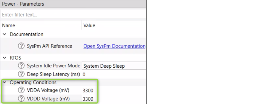
Select the power supply voltage the same as in the Device Configurator under
Operating Conditions
.
