This section provides a simple workflow for how to use the CAPSENSE™ Tuner.
- Create a CAPSENSE™ application with a Tuner communication interface and
program the application into the device. Refer to the Eclipse IDE for
ModusToolbox ™ user guide and the CAPSENSE™
Configurator user guide for more details.Note:The simplest way to start CAPSENSE™ Tuner is to use the PSOC ™ 6 CAPSENSE™ Buttons and Slider code example configured to work on PSOC™ 6 MCU kits or PSOC™ 4 MSC CAPSENSE™ CSD Button Tuning configured to work on PSOC™ 4 MCU kits.
- Launch the CAPSENSE™ Tuner.
- Start Communication. Click Connect and select
the required communication interface.
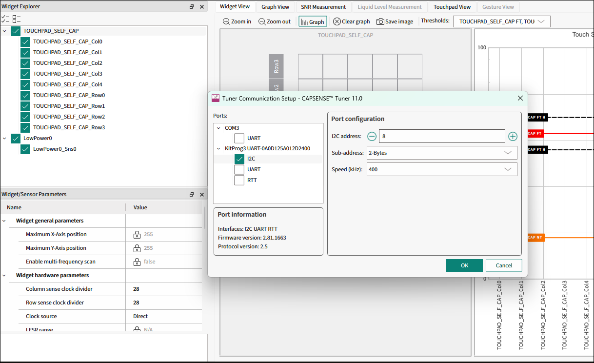
Note:For MiniProg, first, power the device – click the Tuner Communication Setup button to select the communication interface, use the Power button to select and apply the power supply, and proceed with Connect.Note:Refer to the KitProg user guide for the supported configurations and modes. For this example, I2C address, sub-address, and speed must match the configuration.Note:For the I2C communication, the Tuner only supports the 2-Bytes Sub-address. - Click Start to extract data.

- Touch the sensors on the hardware and notice the change in the sensor/widget status on Widget View tab.
- Open the Graph View tab. Check the sensors in the Widget Explorer pane to observe sensor signals on the graph. Touch the sensors and notice the signal change on the Graph View tab.
- Change widget/sensor parameter values as needed. Then, apply the new
settings to the device temporarily using the Apply to Device
command to test these new settings.
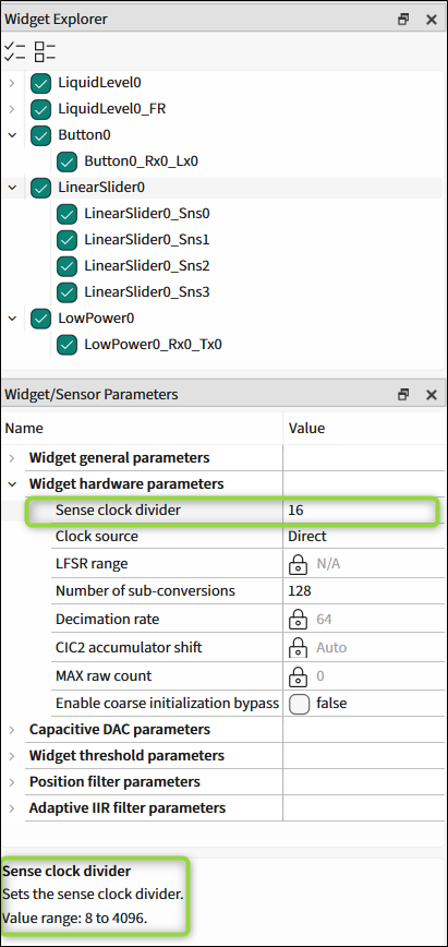
- Exit the Tuner application. After rebuilding the project and re-programming the device, the changes will be applied to the device permanently.