Parameters description
General subtab
The
General
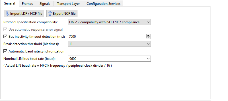
subtab allows general configuration of the LIN resource. The subtab looks as follows:
General subtab parameters
Slave instance properties
The LIN Configurator supports importing NCF and LDF files to configure the LIN slave node and also to export the current configuration into an NCF file. Also, the Configurator automatically configures signals based on LDF/NCF files supplied by the user.

Protocol specification compatibility
This parameter supports the following functionality to select from the drop-down menu:
LIN 2.2 compatibility with ISO 17897 compliance
LIN 2.2 compatibility without ISO 17897 compliance
Use
automatic response_error_signal
This option enables the response_error signal option (response error notification to the LIN master).
If this option is selected, the “RE” signal is added on the
Unplaced Signals
pane on the
Signals
subtab.
Bus inactivity timeout detection (ms)
Select this option to automatically detect the LIN bus inactivity threshold with a free-running timer. The valid range is 4000 ms to 10000 ms.
Break detection threshold (bit times)
Select this option to configure a slave-node break detection threshold. The default value is 11 dominant local-slave bit times. It can be set to either 10 or 11 or 12.
Note:
For the P4000S, P4100S, P4100S Plus, and PSOC™ 4500S series, the actual threshold may be up to one bit less than the specified threshold. For example, if the value of the Break detection threshold option is 11, the actual threshold will be from 10 to 11 bits.
Automatic baud rate synchronization
Enabled by default. You can disable this option.
Enabled – The middleware measures the exact baud rate of the bus from the sync byte field of each LIN frame header.
Disabled – Instead of measuring, the middleware receives the sync byte field as a 0x55 data byte.
Note:
Select this option for successful communication within the cluster if a slave’s clock variance is greater than ±1.5 percent.
Note:
The baud rate synchronization is only used to match one nominal LIN bus baud rate chosen for any given LIN cluster. It is not used to synchronize to any valid baud rate.
Nominal LIN Bus Baud Rate
Enter the
Nominal LIN Bus Baud Rate
at which this slave node must operate. The valid range is 1000 to 20000 baud. The values in the drop-down list are 2400, 9600, 10417, and 19200. Also, you can enter any value between 1000 and 20000 here.
The configurator shows the formula to calculate the actual baud rate:
(Actual LIN baud rate = HFClk frequency / peripheral clock divider / 16)
Frames subtab
The
Frames
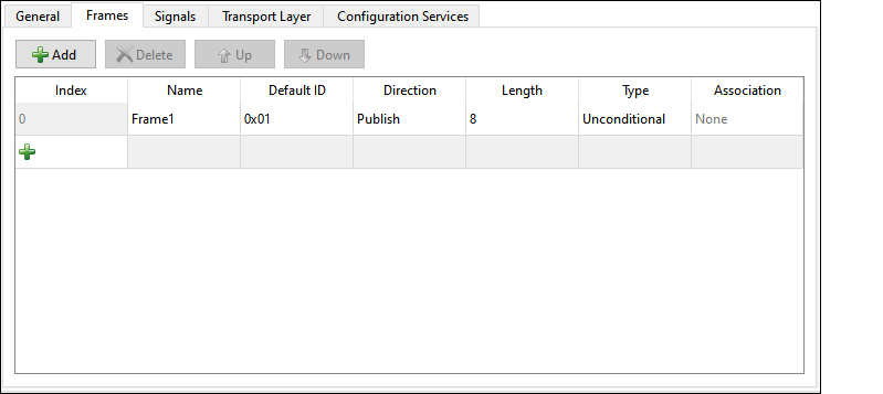
subtab is used to configure how the LIN slave responds to PID values sent by the master on the bus. The
Frames
subtab contains a toolbar to navigate frames and frame configuration table.
Note:
The
Frames
subtab does not show diagnostic frames.
Frames Toolbar
The
Frames
subtab toolbar contains four buttons.
Add – You can start a new frame on the table by either clicking the Add button or the + button at the end of the Index column.
Delete – Removes the currently selected frame from the table. The index number fields are changed accordingly.
Note:
If a frame is deleted on this subtab, any signals configured on the
Signals
subtab and placed into it are relocated into the Unplaced Signals pane.
Up / Down – Reorder the Index number values for each frame.
Frames configuration table
The table contains eight columns.

Index – Shows the ordering number of each used frame. These numbers cannot be directly modified.
You can start a new column clicking the Add (+) button at the end of the Index column.
Name – Displays the unique name of each frame. To change the name, click on it.
Default ID – Defines the frame ID that the frame will use before any configuration requests by the master. Note that the LIN master can reconfigure frame IDs at run time. Enter a value from 0x00 to 0x3B in the hex format into these cells.
Direction – Provides two drop-down options for each frame to select the direction to send the data for the frame:
Publish – Data transmission.
Subscribe – Data reception.
Length – Defines how many bytes are received or sent for each frame. The valid range is 1 - 8.
Type – Provides two drop-down options for each frame to select the frame type:
Unconditional
Event-triggered
For more details, refer to the next paragraph Association .
Note:
You cannot choose the Event-triggered type for a Subscribe frame. If you change this cell from Event-triggered to Unconditional, you must change the value of this frame to “None” in the Association column, if its name appears in any cells in that column.
Association – Used to relate unconditional frames with event-triggered frames. Allows the selection of the frame name of any unconditional frames that are not already associated with an event-triggered frame.
An event-triggered frame must have at least one conditional frame associated with it. The valid values for this setting are the names of any existing unassociated unconditional frames. Only one unconditional frame can be associated with an event-triggered frame. As a result, when one of these cells has the name of an unconditional frame in it, this unconditional frame name cannot be available to any of the other rows.
Signals subtab
The
Signals
subtab is used to specify the parameters of signals added into the LIN frames.
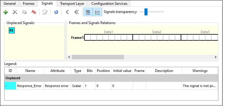
The subtab toolbar and panes – Unplaced Signals, Frames and Signals Relations, Legend – are described in the following sections.
Signals toolbar
The Signals toolbar contains buttons to configure and navigate signals:
Add signal – Puts a new signal on the Unplaced Signals pane. The
Signal Properties
dialog displays after clicking this button.
Delete signal – Removes the selected signal. A warning will display first.
Clone signal – Duplicates the selected signal.
Note:
If the duplicated and original signals have the same name, a warning about the parameters and location of such signals will display.
Delete all signals – Removes all signals. A warning will display first.
Signal properties – The Signal Properties dialog of the selected signal displays after clicking this button.
Renumber signals’ IDs – Reorders the signals index values.
Move signal to unplaced – Relocates the selected signal to the Unplaced Signals pane.
Move all signals to unplaced – Relocates all signals to the Unplaced Signals pane.
Show/hide event-triggered frames – Shows or hides event-triggered frames.
Show/hide Legend – Shows or hides the Legend pane.
Signals transparency – This slider sets the transparency for signals graphics.
Unplaced Signals
The Unplaced Signals graphical pane serves as temporary to store added signals. Signals can be moved back and forth between the Unplaced Signals pane and the Frames and Signals Relations pane.
Note:
If a frame is deleted on the Frames subtab, any added to it signals (configured with the Signals subtab) are moved into the Unplaced Signals pane.
To display the “RE” symbol here, select the
Use automatic response_error_signal
option on the General subtab. Double-clicking this symbol opens the Signal Properties dialog.

Frames and Signal Relations
The Frames and Signal Relations graphical pane of the
Signals
subtab displays interactive graphics of the configured frames and signals.
Each frame graphic represents a frame added (configured) in the
Frames
subtab.

One frame length can be any from 1 to 8 data bytes. Each byte contains eight 1-bit cells: Data1 through Data8. The total number of frames cannot exceed 60. The total size of all frames is limited to 256 bytes.
Each signal graphic represents one signal defined for the LIN slave. The graphic for a signal appears as a solid bar. A signal is placed onto the frames using the drag-and-drop function. Placed signals occupy bits or bytes of the frames. Clicking a signal symbol selects that signal. Double-clicking a signal symbol opens the Signal Properties dialog.
Graphical Interaction between Unplaced Signals and
Frame and Signals panes
The interactive graphical panes of the Signals subtab allow selecting signals by clicking them, then, dragging and dropping them onto the frames:


The graphical panes may look as follows depending on the selected signals’ parameters and graphic color:

Signal Properties
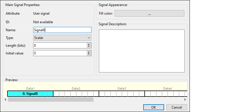
The "Signal Properties" dialog contains various parameters to configure signals.
The "Signal Properties" dialog displays if you click the
Add
button on the toolbar to configure and add a new signal or double-click an already configured and added signal’s symbol to edit its configuration.
Main Signal Properties
Attribute – The attribute value cannot be modified. The field displays the following values depending on the various signal configuration:
User signal – The default value.
Response error – Enable the Use automatic response_error_signal option on the General subtab. To display it on the "Signal Properties" dialog, click on the “RE” symbol and click the Signal properties button on the Signals subtab toolbar.
ID – The ordering number of a signal placed on a frame. Cannot be directly modified.
Name – The default signal name is Signal0, where “0” is equal to the signal index number. The signal name can be changed but it must contain only letters, digits, and underscores.
Type – There are two types of signals:
Scalar – A signal of 1- to 16-bit length
Byte array – A signal of 1- to 8-byte length.
If the Byte array type is selected, the Initial value parameter displays as many fields for entering values as there are bytes in the Length parameter:
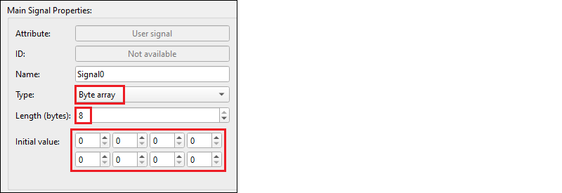
Length (bits) – The length of a signal: 1-16 bits for Scalar signals; 1- 8 bytes for Byte array signals.
Initial value – The initial value must be entered in the decimal format.
Signal Appearance
Fill color – Clicking the color bar displays the dialog where to select the signal graphic color and its parameters.

Signal Description
Any signal-related description or other information entered by the user.
Preview
The Preview graphical pane shows what the signal will look like when it is added.
Legend
The Legend pane describes the properties of configured signals.
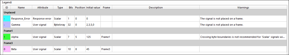
The descriptions of the Legend pane columns – ID, Name, Attribute, Type, Bits (Length (bits), Initial Value, Signal Description – are available on the
Main Signal Properties
pane of the "Signal Properties" dialog as they are properties of the same configured signals. Also, the Legend pane consists of the following columns:
Position – Indicates the start bit where a signal is located on a frame. The range is 0-63.
Frame – The name of the frame where a signal is located.
Warnings – These are notices related to the configured signals.
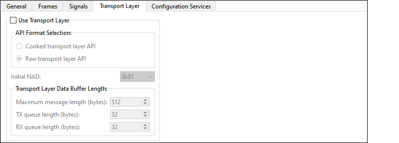
Transport Layer subtab
The
Transport Layer
subtab contains parameters to configure the API and data buffer length.
Note:
The transport layer itself defines transportation of data contained in one or more frames. See the LIN 2.2 or ISO 17987 specification for detailed information on the Transport Layer.
Use Transport Layer
If you select this option, a warning displays to ensure that the values entered on the Configuration Services subtab are correct.
If you deselect this option, a warning displays that the Automatic Configuration Request Handling option will also be disabled.
API Format selection
This section is used to select the format for the Transport Layer API functions:
Cooked transport layer API – The cooked format is used to send and receive Transport Layer messages. It is the user’s responsibility to ensure that just one API function is used for each message.
RAW transport layer API – The raw format is used to send or receive each frame that makes up a Transport Layer message using one API function call for each frame.
Initial NAD
This field is used to select the Network Address (NAD) of the slave node. Each slave node has an initial NAD list. The NAD is used in MRF and SRF frames to address one particular slave node in a cluster. Note that this field is used to select the initial NAD for the node. The NAD of a slave node can change at run time.
Transport Layer Data Buffer Length
Maximum message length (bytes) – This property is used to select the maximum Transport Layer message length that this slave node supports. The minimum value is 6. This configurator only supports Transport Layer messages with lengths up to 4095 bytes.
TX queue length / RX queue length (bytes) – These properties are only applicable when the Raw Transport Layer API format is selected. The configurator supports queue lengths from 8 to 2048 with 8-byte steps. The default size of each queue is 32 bytes.