GUI description
ModusToolbox™ Programmer contains menus and toolbar commands to perform actions. This chapter describes the various GUI elements.
Menus
File
The
File
menu contains the following commands:
Open (Ctrl+O) – Opens the programming file.
Connect/Disconnect (Alt+Q) – Connects and disconnects the selected device.
Program (Alt+G) – Programs the selected device with the selected file.
Erase (Alt+E) – Erases the selected device.
Read (Alt+R) – Reads flash of the selected device into a HEX or SREC file.
Verify (Alt+Y) – Verifies that the selected device is programmed correctly.
Recent Files – Lists up to five recently loaded programming files.
Exit (Alt+F4) – Closes the ModusToolbox™ Programmer application.
View
The
View
menu contains the
Settings
check box. Select it to view the
Settings
section of the window; unselect it to hide the
Settings
section. See
Settings
.
Options
The
Options
menu contains the following commands:
Programmer Options (Alt+T)
Opens the Programmer Options dialog to set the
Upgrade Firmware
mode and other options.
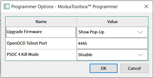
Upgrade Firmware
mode:
Automatically – The firmware is updated automatically when the tool opens.
Show Pop-up – A dialog displays asking if you want to upgrade the firmware.
Ignore – The firmware is not updated and no prompt displays.
OpenOCD Telnet Port
: This option specifies the port number of the OpenOCD telnet connection.
Kill Mode
: Use this option to enable/disable the transition into Kill mode for PSOC™ 4, PMG1, PAG2S, WLC1 and CCGx devices
Upgrade Firmware (Alt+U)
When this command is enabled, select it to upgrade the programmer firmware on the device.
Verify Regions
The Verify Regions menu is available only if Verify Regions option is selected in Program Settings .
Add Region – Adds a custom flash region to the Verify Regions list.
Reload Regions – Resets the Verify Regions list to the default state corresponding to the flash map of the target.
Undo (Ctrl+Z) – Undo the last change in the Verify Regions list.
Redo (Ctrl+Y) – Redo the last change in the Verify Regions list.
Verify – Initiates the Verify device operation.
Help
The
Help
menu contains the following commands:
View Help (F1) – Opens this document.
About ModusToolbox™ Programmer – Opens the About box.
Toolbar
The toolbar contains the
Open
,
Connect
,
Erase
,
Program
,
Read
, and
Verify
commands, which are also located on the
File
menu. This area also contains the following:
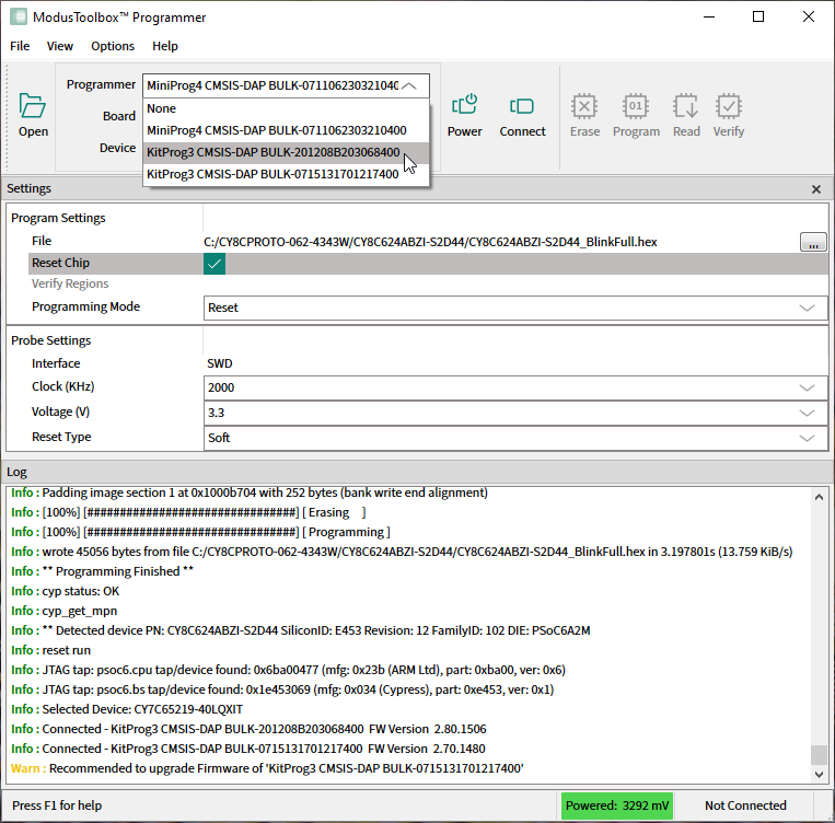
Programmer, Board, and Device
Use these pull-down menus to select the specific device to use.
Programmer
This displays a list of all currently connected probes with a serial number or other identifier (for example, COM port number) from which you can select the desired Programmer.
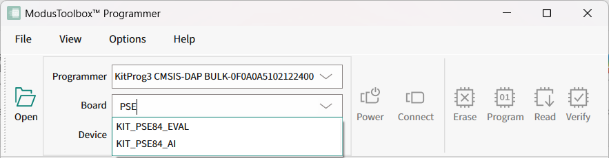
Board
The
Board
pull-down allows you to choose the appropriate Kit name for the selected
Programmer
.
Under the Scanned Boards entry, there is a short list of best matched Kit names detected by the tool.
Under the Others entry, there is a list of all other Kit names available for the selected programmer device.
When selecting the Custom board, the tool allows you to manually specify the particular target device connected to a stand-alone programmer (such as MiniProg4) or a KitProg3 with modifiable MCU module. Custom board is only available for KitProg3, MiniProg4 and JLink programmers.
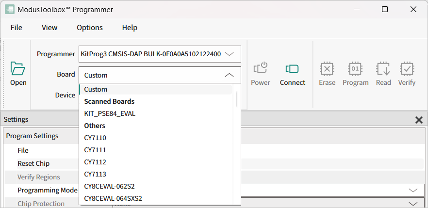
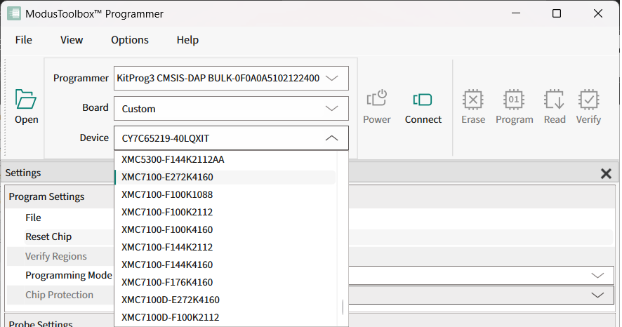
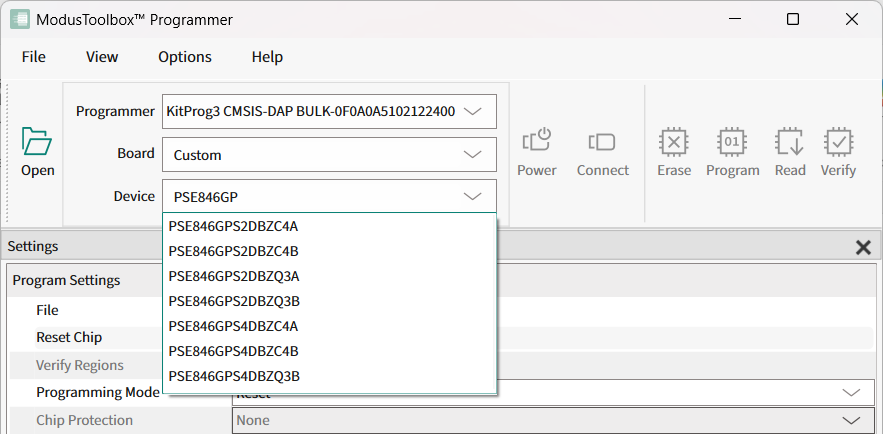
Device
This displays a list of all supported target devices. It is enabled only if you select Custom for the Board option.
Auto-completion
Board
and
Device
pull-downs support auto-completion.
Start typing the name of the Kit in the
Board
pull-down and the tool will suggest corresponding board names.
Start typing the device’s part number in the
Device
pull-down and the tool will suggest corresponding target devices.
Power
Use the
Power

button to power on and off the selected device.
Connect
Use the
Connect

button to connect to and disconnect from the selected device.
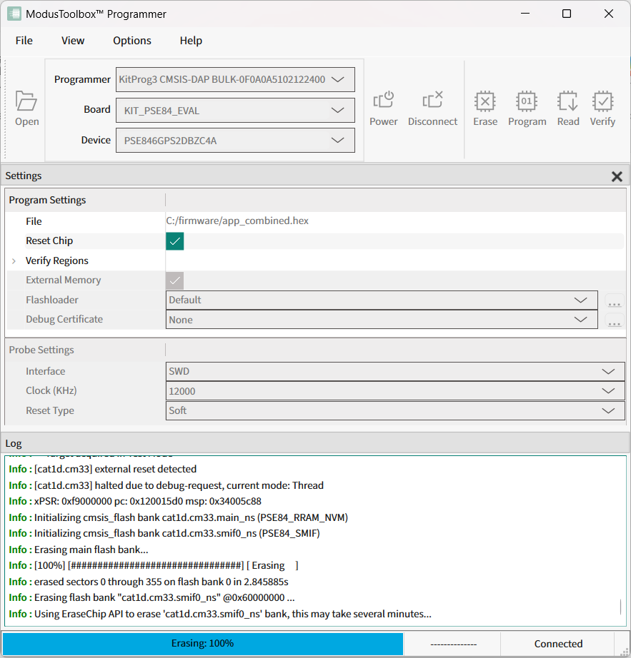
Settings
The
Settings
section of the tool allows you to update the program and probe/target settings as follows:
Program Settings
File – Use this to select the programming file to perform actions on or with.
Offset – This is an optional offset parameter; it can be an integer or hexadecimal value. The relocation offset is added to the base address for each section in the image when the image is programmed. This option is visible only if a binary or elf file is selected for programming operations.
Reset Chip – Use this to reset the chip after the Program operation completes. This option resets the target chip and runs the programmed firmware on it.
Verify Regions – Use this option to define flash regions used during device verification. This allows to verify user defined flash regions of the PSOC™ MCU. This option does not change behavior of the Program operation. See Verify custom flash regions for details.
External Memory – Enables/disables the programming of external memory in the target device. For PSOC™ 6x MCUs, this option enables programming of the QSPI regions. This is also used for programming external memory of AIROC™ Wi-Fi devices.
Program Security Data – Allows programming security regions if the target device supports this capability. For example, for PSOC™ 61 PSOC™ 62, and PSOC™ 63 MCUs, this option enables programming the eFuse region.
Target AP – Allows you to select the target access port (DAP) that will be used for programming. Possible values include: CM0, CM4, and SYS_AP. This option is available only for PSOC™ 64 MCUs.
Flash Size Limit – Limits the size of application flash available for programming operations. This option is available only for PSOC™ 64 MCUs.
Programming Mode – Use this option to define programming mode for PMG1 devices. The mode options include:
Reset: This programming mode enables acquisition of the target device in the Test mode.
PowerCycle: In this mode, the programmer cycles power to acquire the device.
Flashloader – Use this option to select the patched QSPI CMSIS flashloader file (in FLM format). This flashloader is used for external flash programming.
Note:
To be able to program custom external flash you should also provide the appropriate QSPI configuration file (qspi_config.cfg), generated by the ModusToolbox™ QSPI Configurator tool. This file should be located in the same directory as the patched flashloader file.
Debug Certificate – Use this option to specify the location of the debug certificate binary file. The debug certificate is used for programming AIROC™ CYW20829 targets in Secure lifecycle mode.
ECC Config – Use this option to enable or disable the ECC error reporting. This option is only applicable for read flash operations of some MCUs.
Chip Protection – Use this option to apply Chip Protected or Kill mode for PSOC™ 4, PMG1, PAG2S, WLC1 and CCGx devices.
RRAM Offset – Use this option to modify the offset for RRAM memory (flash bank) for PSOC™ Edge E84 EPC4 devices. The minimal allowed RRAM offset value is 0xA000.
Probe Settings
The
Probe
settings allow you to configure the programming and target device before you connect to it. These settings are available when ModusToolbox™ Programmer is not connected to the device.
Interface – To select the hardware (debug) interface for communication with the target device. The possible values include: SWD and JTAG if supported by the device.
JTAG Chain – To select the interested target device in the JTAG chain. This option is only available for probes supporting JTAG interface. See Program PSOC™ 6/Control C3/Edge E84 MCU in JTAG chain for details.
Voltage (V) –To select the power supply voltage of the target device in Volts. This option is available only if the selected probe has the power control capability.
Clock (KHz) – To select the frequency of the hardware interface in KHz. This option is available only if the selected probe supports configurable frequencies.
Reset Type – Specifies the type of the Reset Chip operation. The possible values include: Soft and XRES:
Soft is a software reset type that sends the system reset request to the ARM core.
XRES is a hardware reset type that toggles the XRES hardware line.
Sflash Restrictions – Specifies the Sflash programming behavior. This option is available only for PSOC™ 61/62/63, XMC7xxx/XMC5xxx, FX3G2, CYT3Bx/CYT3DL, CYT4Bx, CYT4DNJ, and CYT2Bx MCUs. The possible values include:
Erase/Program of Sflash is prohibited.
Erase and Program of USER/TOC/KEY is allowed.
Erase of USER/TOC/KEY and Program of USER/TOC/KEY/NAR is allowed.
Erase and Program of entire Sflash is allowed.