GUI description
Menus
File
Open… – Opens an existing input file of the supported formats. If a file is already open, it will be closed.
Save Log As… – Opens the dialog to save the log file in a specified location.
Clear Log – Clears the current log.
Exit – Closes the DFU Host tool.
Actions
Program – Programs the application to the device.
Execute – Executes the . mtbdfu file on the host, establishes a DFU session with the target and processes the DFU commands
Verify – Verifies the programming of the device.
Erase All – Erases the program from the device.
Abort – Aborts the action.
View
Toolbar – Shows/hides the toolbar.
Help
View Help – Opens this document.
About Device Firmware Update Host Tool – Opens the About box for version information, with links to open https://www.infineon.com and the current session log file.
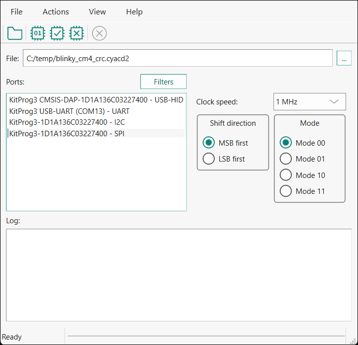
Main window
File selection
This section describes how to select the input file, which contains the DFU commands or firmware image.
* .mtbdfu file configuration
The
Configure
and
Generate
buttons display when one or more *
.hex
files are passed as an input. Click the
Configure
button to display the "Configuration" window.
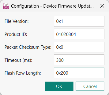
Enter the
.mtbdfu file
parameters to generate an
*.mtbdfu
file that is used to program/verify/erase the selected
.hex
files.
Ports
This section lists all ports attached to the computer to communicate with the bootloader. Based on which item is selected, different options are available for the
Port Configuration
.
Filters...
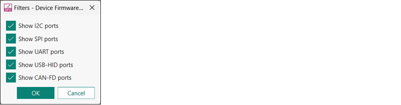
Use the
Filters
button to select which ports display in the
Ports
list.
Port configuration
This section allows for configuring the interface-specific options for communicating with the DFU system. This is necessary to ensure both the DFU and host computer are configured the same.
Refer to the appropriate probe documentation for a list of supported modes.
Note:
Not all SPI and UART communication properties combinations are supported.
I2C
For I 2 C communication, there are two required parameters:
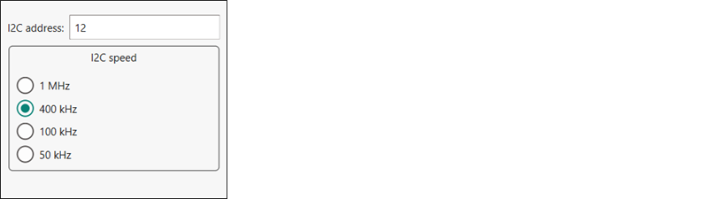
The address of the I 2 C-based target DFU system with which the host is communicating. The range for valid addresses is from 8 - 120.
The I 2 C SCK signal frequency.
Note:
Note: It may happen that the device sends neither ACK nor NACK signal. In this case, it may take the DFU Host tool up to 20 seconds to send a timeout error.
SPI
For SPI communication, there are three required parameters:
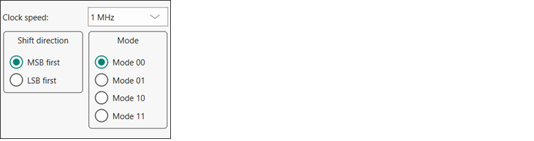
The SPI SCLK signal frequency.
The bit ordering of transferred data.
The SPI operating mode.
UART and USB-CDC
For UART/USB-CDC communication, there are four required parameters:
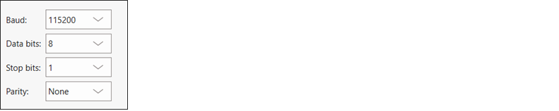
The baud (bit) rate at which data is transferred.
The number of data bits per byte.
The number of stop bits indicating the termination of a byte.
The parity bit that is added to a byte.
Note:
Note: KitProg3 and MiniProg devices do not support custom values for data bits, stop bits, and parity. They are set to 8 data bits, 1 stop bit, and no parity respectively and cannot be changed.
USB-HID
USB-HID does not need port configuration. Both VID and PID are obtained automatically the device name is selected.
CAN-FD
For CAN-FD communication, there are five required parameters:
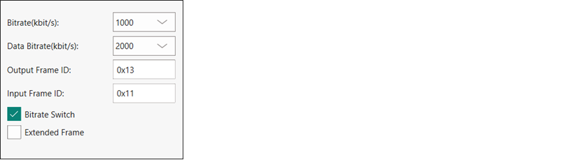
The bitrate at which data is transferred.
The data bitrate at which data is transferred if bitrate switch is enabled.
The output Frame ID for each sent frame.
The bitrate switch to enable switching between bitrate and data bitrate.
Extended Frame to enable extended frame support.
There is also the optional parameter
Input Frame ID
, which filters an incoming CAN-FD frame by its frame ID. Leave this field empty if you do not use it.
The CAN-FD middleware supports one of the following configurations:
Nominal Bitrate
(kbps) | Data Bitrate
(kbps) | |||||||
|---|---|---|---|---|---|---|---|---|
125 | 250 | 500 | 1000 | 2000 | 4000 | 8000 | 10000 | |
Clock Frequency (Mhz) | 80 | 80 | 80 | 80 | 80 | 80 | 80 | 80 |
Prescaler | 40 | 20 | 10 | 10 | 4 | 2 | 2 | 1 |
Time Segment 1 | 12 | 12 | 12 | 5 | 7 | 7 | 7 | 5 |
Time Segment 2 | 3 | 3 | 3 | 2 | 2 | 2 | 2 | 2 |
Synchronization Jump Width | 1 | 1 | 1 | 1 | 1 | 1 | 1 | 1 |
Log
The log displays the history of what happened while the host was open:
when operations started/completed
information about user-initiated operations
error messages during an operation if any.
Errors
Any errors for various fields display as a red X in the field containing the error, and it contains a tooltip when you hover the mouse cursor on it.