GUI description
The EZ-PD™ Configurator GUI contains menus, the main toolbar, and tabs with toolbars to configure the various parameters, as well as Notice List and Status bar to provide indications
Menus
File
New – Creates a new file with new configuration.
Open – Opens the configuration file.
Close – Closes the configuration file.
Save – Saves the existing file.
Save As – Saves the existing file under a different name.
Open in System Explorer – Opens your computer’s File Explorer browser to the directory that contains the *. mtbezpd file.
Exit – Closes the configurator.
Edit
Add Port – Adds a new Port tab to configure parameters.
Remove Port – Removes the selected Port tab.
Copy Port – Copies port settings of the selected port to the clipboard.
Paste Port – Pastes port settings from the clipboard to the selected port; replaces current settings.
Undo – Undoes the previous change.
Redo – Redoes the last undone change.
View
Notice List – Shows/hides Notice List. The pane displays by default.
Toolbar – Shows/hides the toolbar.
Reset View – Resets the view to the default.
Help
View Help – Opens this document.
About EZ-PD™ Configurator – Opens the About box for version information, with links to open https://www.infineon.com and the current session log file.
Notice List
The
Notice List
pane combines notices (errors, warnings, tasks, and infos) from many places in the configuration into a centralized list. You can double-click a notice location to show the parameter causing the error or warning. For more information about the Notice List, refer to
Device Configurator user guide
.
Status bar
The status bar displays various information, including a file operation status, hints, input field ranges, etc. On the right side, it displays the selected device.
Toolbar
The toolbar contains common commands from the
File
and
Edit
menus, such as
New
,
Open
, and
Save
. Use the check box under the
View
menu to show or hide the toolbar.

Port tabs
This area contains one or two tabs to configure various parameters. Each tab includes a toolbar with the following commands:

Add/Remove PDO – Adds or removes a PDO from the selected list.
Sort PDOs – Toggles Sort on and off. When enabled, this reorders the PDOs by type and voltage.
Move Up/Down – When Sort is disabled, these move the selected PDO up or down in the list.
Expand/Collapse All – Expands or collapses the entire tree of items in the Port tab.
Parameter categories
The left pane of the EZ-PD™ Configurator shows the following parameter categories:
Parameters and values
The following sections describe the parameters available for each category. Select a parameter category to see that category individual parameters and values as appropriate on the right pane of the EZ-PD™ Configurator.
Port Information
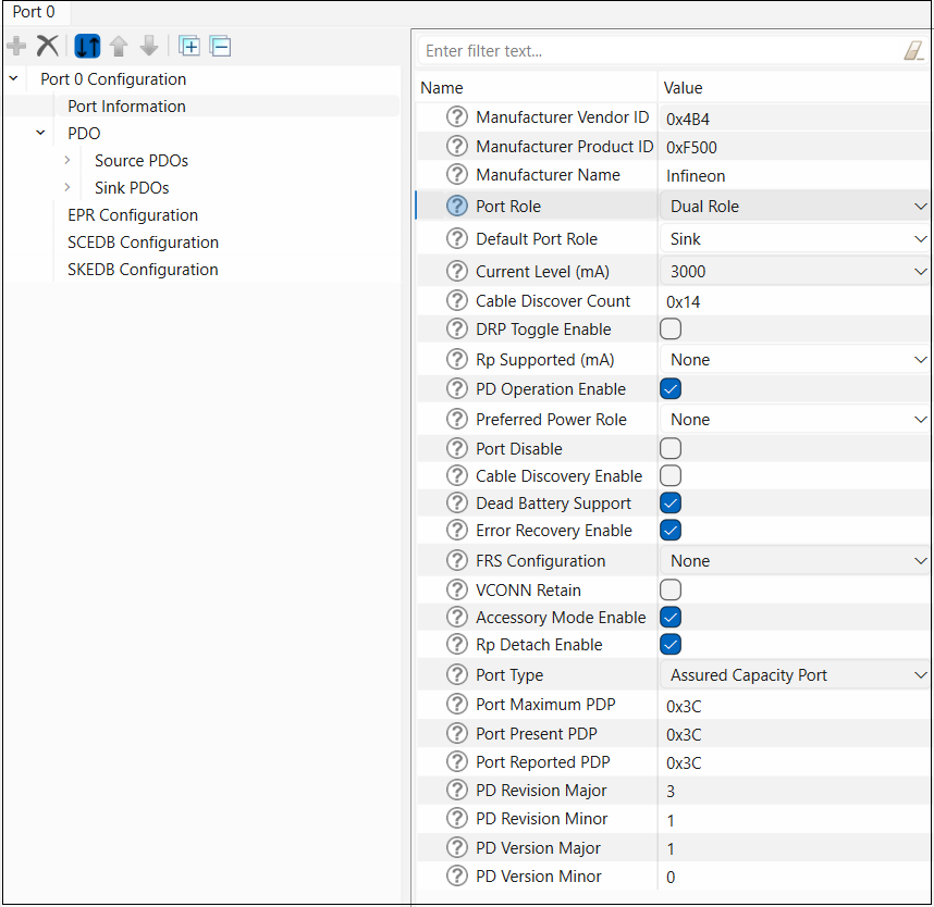
The
Port Information
node consists of the following parameters:
Field name | Description | Valid range |
|---|---|---|
Manufacturer Vendor ID (0x) | Vendor ID assigned to manufacturer by USB-IF | 0x0000 – 0xFFFF |
Manufacturer Product ID (0x) | 16-bit Product ID that identifies the product | 0x0000 – 0xFFFF |
Manufacturer Name | Manufacturer name string | Maximum 21 ASCII Characters |
Port Role | Power handling role of the device | 0 -> Sink 1 ->Source 2 -> Dual Role |
Default Port Role | Default power handling role of the device | 0 -> Sink 1 -> Source |
Current Level (mA) | Operating current range for the device | 0 -> 900 mA 1 -> 1.5 A 2 -> 3 A |
Cable Discover Count | Number of cable discovery attempts to be made | 0x00 – 0x14 |
DRP Toggle Enable | Whether Rp-Rd toggle is enabled in unattached state | Check box enabled or not. |
Rp Supported (mA) | Rp values supported by the device | Bit Mask Bit 0 -> 900 mA Rp Bit 1 -> 1.5 A Rp Bit 2 -> 3 A Rp |
PD Operation Enable | Whether USB-PD operation is supported on the port | 0 -> No 1 -> Yes |
Preferred Power Role | Whether Try.Src or Try.Sink is enabled for the port | 0 -> No Try.Src or Try.Sink supported 1 -> Try.Src supported 2 -> Try.Sink supported |
Port Disable | Whether the PD port is to be disabled at start-up | Check box enabled or not. |
Cable Discovery Enable | Whether cable discovery is enabled as part of the source state machine | Check box enabled or not. |
Dead Battery Support | Whether dead battery operation is supported | Check box enabled or not. |
Error Recovery Enable | Whether Type-C error recovery is enabled for this port | Check box enabled or not. |
FRS Config | Fast Role Swap feature enabled flags | 0 -> None 1 -> FRS receive enable 2 -> FRS transmit enable |
VCONN Retain | Whether Vconn supply should be left enabled even if the EMCA's cable VDO indicates that Vconn is not required. | Check box enabled or not. |
Accessory Mode Enable | Whether accessory mode is to be enabled | Check box enabled or not. |
Rp Detach Enable | Option to enable/disable disconnect detect mechanism using Rp in Sink role | Check box enabled or not. |
Port Type | Port type in Source_Info data object. Indicates whether the amount of power the port can provide is fixed or can change dynamically | 0 -> Shared Capacity Port 1 -> Assured Capacity Port |
Port Maximum PDP | The maximum amount of power the port is designed to deliver | 0x00 – 0xFF |
Port Present PDP | The amount of power the port is presently capable of offering | 0x00 – 0xFF |
Port Reported PDP | The amount of power the port offering in its Source_Capabilities or EPR_Source_Capabilities message. | 0x00 – 0xFF |
PD Revision Major | PD revision major | 0x0 – 0xF |
PD Revision Minor | PD revision minor | 0x0 – 0xF |
PD Version Major | PD version major | 0x0 – 0xF |
PD Version Major | PD version major | 0x0 – 0xF |
PDO
This node represents the set of Power Data Objects (
PDOs
) for the selected device. The PDOs supported by the device are arranged hierarchically. PDOs can be
Source PDOs
or
Sink PDOs
, depending on whether they describe the power sourcing or sinking capabilities of the USB-PD device. All fields listed under the
Source PDOs
and
Sink PDOs
nodes are defined in the USB-PD specification, revision 3 classified as follows:
Fixed Supply
Battery
Variable Supply
Programmable Power Supply
Adjustable Voltage Supply
You can add or remove
PDOs
using
Add/Remove PDO
buttons available in
Port tabs
. Each PDO contains an
Enable
check box, which specifies whether the PDO is enabled at system start-up.
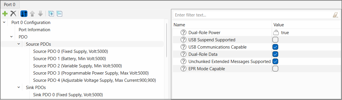
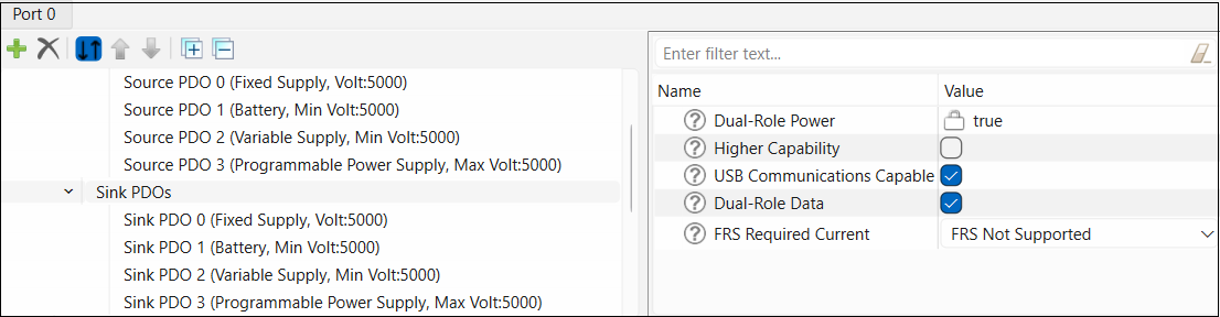
Source PDOs
The
Source PDOs
node displays only when the value of
Port Role
parameter is set to Source or Dual Role in
Port Information
node.
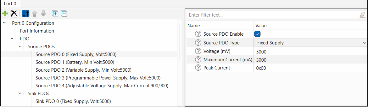
The parent
Source PDOs
node contains the following parameters from
5V Fixed Supply Source PDO
:
Fixed Supply Source PDO configuration parameters
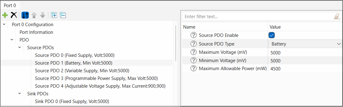
Battery Source PDO configuration parameters
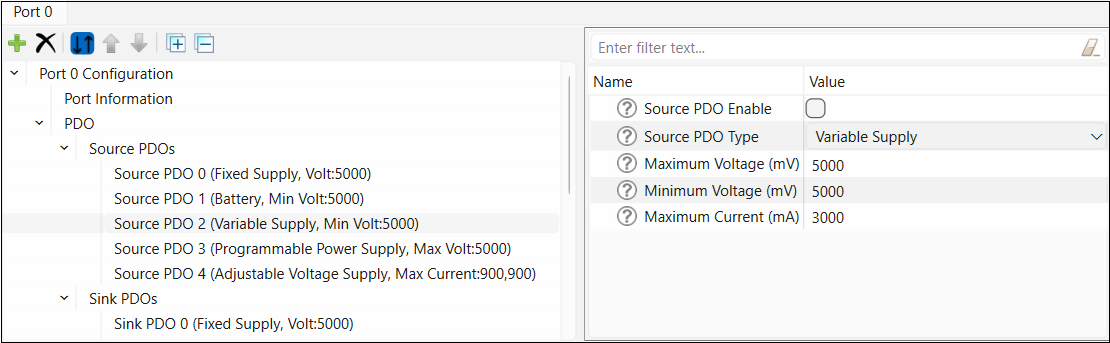
Variable Supply Source PDO configuration parameters
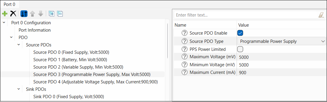
Programmable Power Supply Source PDO
configuration parameters
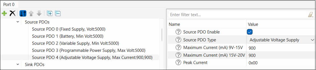
Adjustable Voltage Supply Source PDO
configuration parameters
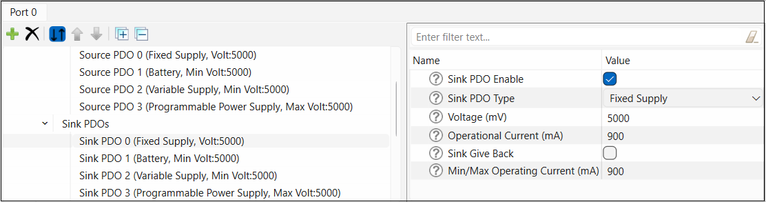
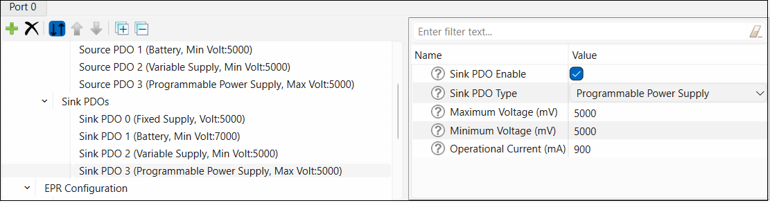
Sink PDOs
The
Sink PDOs
node displays only when the value of the
Port Role
parameter is set to Sink or Dual Role in the
Port Information
node.
Sink PDO
configuration includes two additional parameters:
The Sink Give Back parameter specifies whether the feature is enabled for this PDO.
The Min/Max Operating Current parameter specifies the minimum current required for device operation if give back is enabled. If give back is disabled, this field specifies the maximum operating current that may be required.
The parent
Sink PDOs
node contains the following parameters from 5V Fixed Supply Sink PDO:
Fixed Supply Sink PDO
configuration parameters
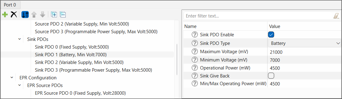
Battery Sink PDO
configuration parameters
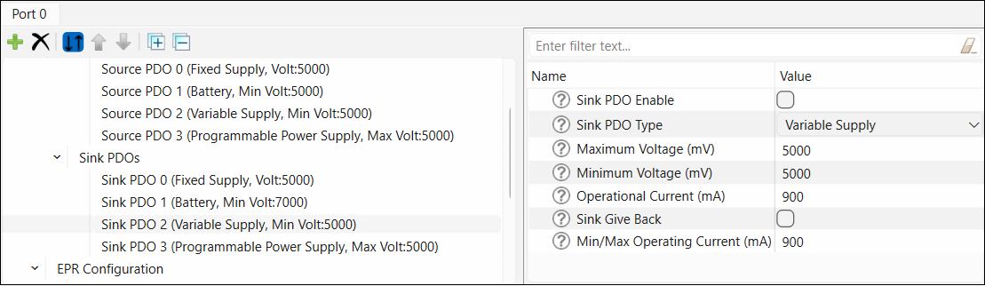
Variable Supply Sink PDO
configuration parameters
Programmable Power Supply Sink PDO
configuration parameters
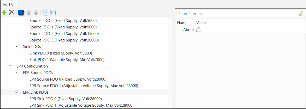
EPR Configuration
This contains a check box to enable or disable
Extended Power Range
(
EPR
)
configuration
.
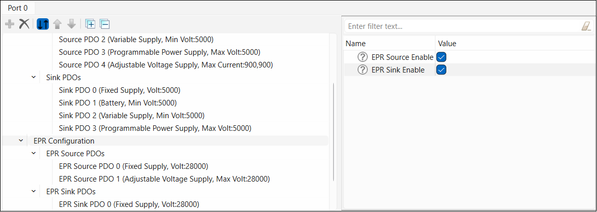
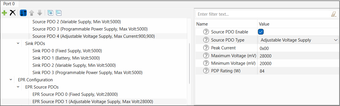
EPR Source PDOs
Enable
ERP Source
to display one or more
EPR Source PDOs
.
Fixed Supply
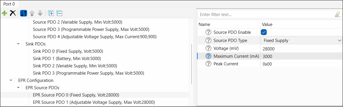
Adjustable Voltage Supply
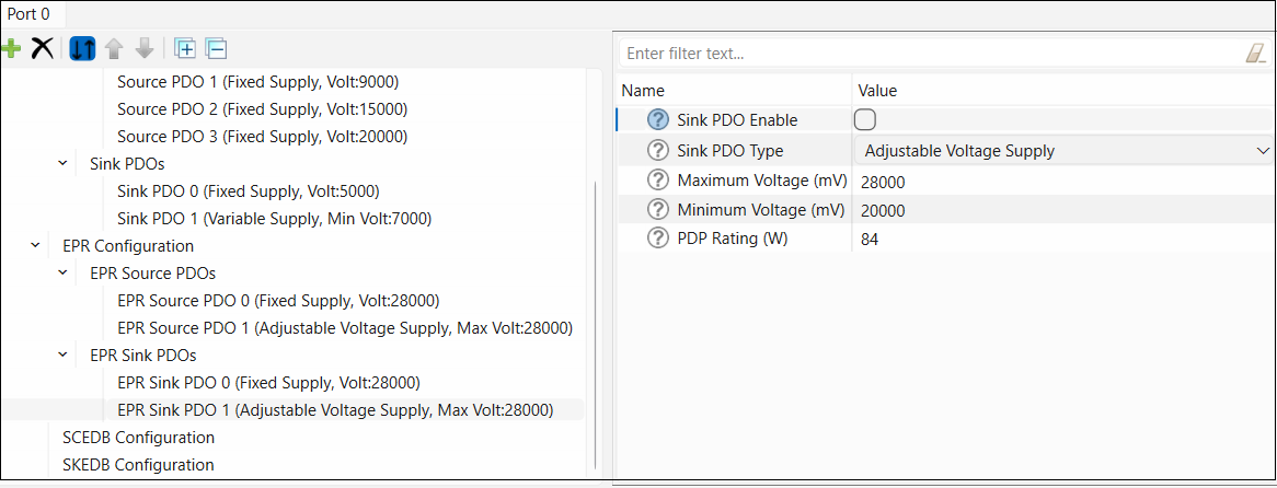
EPR Sink PDOs
Enable
EPR Sink
to display one or more
EPR Sink PDOs
.
The
EPR Sink PDOs
configuration parameters:
Fixed Supply
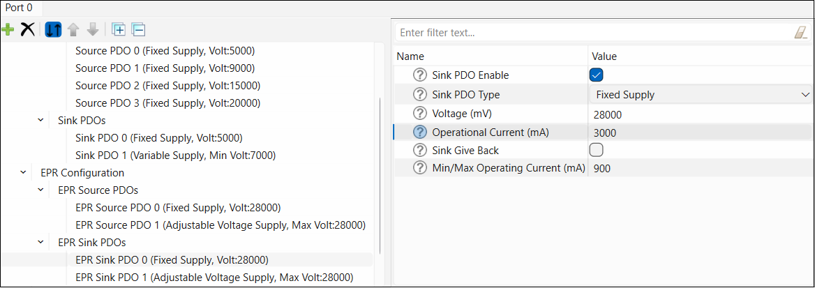
Adjustable Voltage Supply
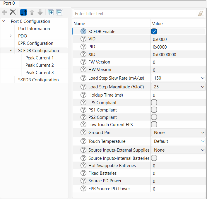
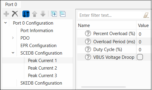
SCEDB Configuration (Source Capabilities Extended Data Block)
This contains a check box to enable or disable
Source Capabilities Extended Data Block
(
SCEDB
) parameters. These are based on the USB-PD specification, revision 3, section 6.5.1.
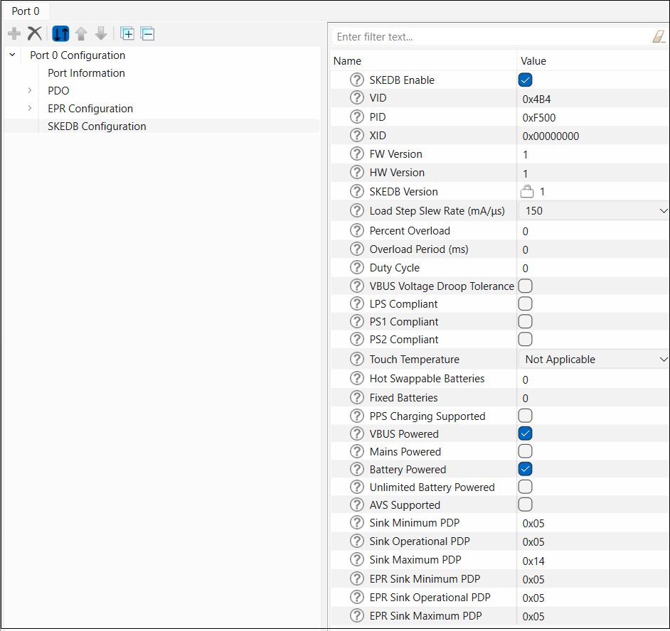
SKEDB Configuration (Sink Capabilities Extended Data Block)
This contains a check box to enable or disable
Sink Capabilities Extended Data Block
(
SKEDB
) parameters. These are based on the USB-PD specification, revision 3, Section 6.5.13.