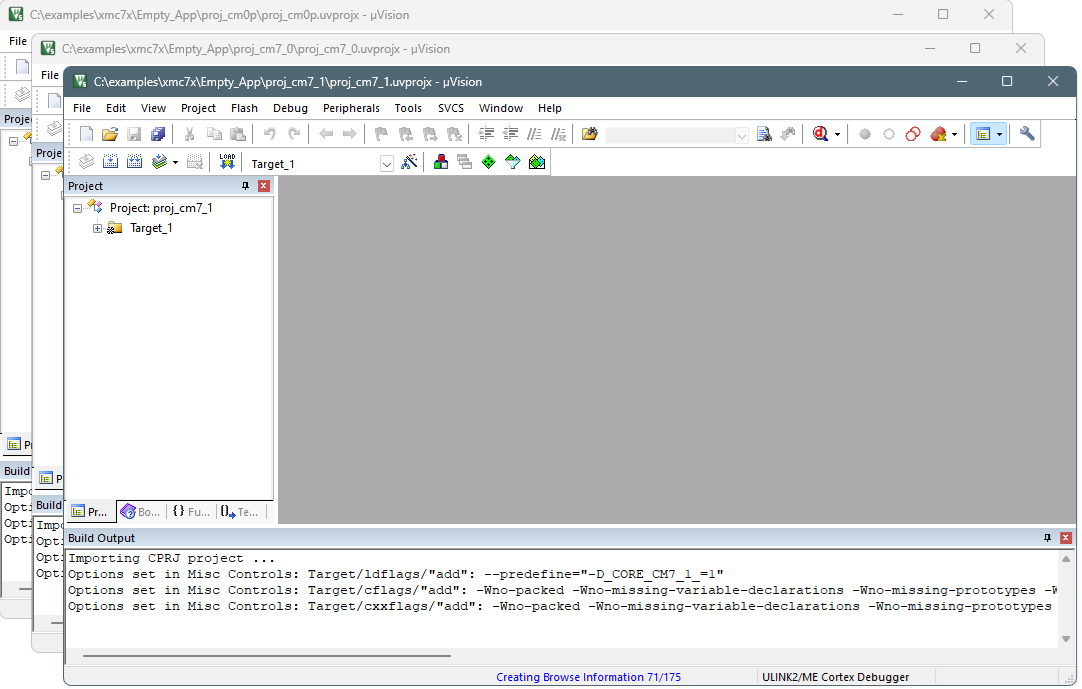
Then, use the instructions in this section to configure, build, and debug your application.
Configure CM0+ project
- Go to Project > Options for Target
<target_name>, switch to the Debug tab, select the applicable debug probe (CMSIS-DAP or J-Link) as
shown:

- If using ULINK2, select the CMSIS-DAP Debugger option as the debug probe, because the ULINK2 driver does not support multi-core debugging
- Click the Settings button to configure the target driver.
- If you select the J-Link probe, a pop-up window might display
reporting that the device is unknown to J-Link software.
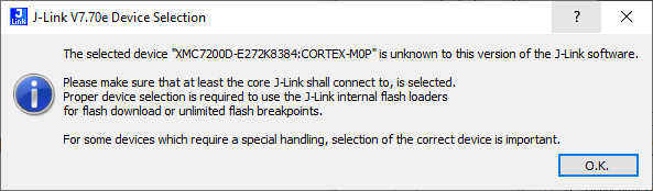
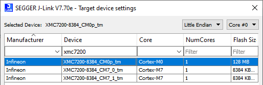
- If so, click OK and select
the device manually in the opened Target device settings dialog. For XMC7200
devices, there will be three aliases, each dedicated to a separate core.
- If you select the J-Link probe, a pop-up window might display
reporting that the device is unknown to J-Link software.
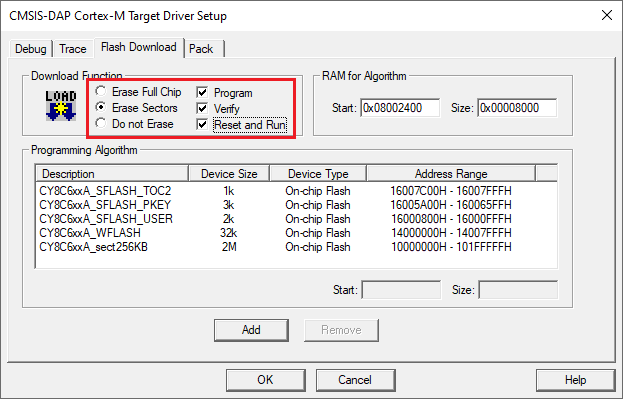
- Switch to the Flash Download
tab, select the Erase Sectors radio button, and
select the Program, Verify, and Reset and Run check
boxes.
- Click OK to close the Target
Driver Setup dialog.
- Next, configure the project so that it also programs other image(s)
from the CM4/CM7 project(s). Do this using the *.ini file.
- Create a new empty file named load_cmx.ini and save it inside the CM0+ project directory.
- Add a
LOADcommand with a path to the CM4/CM7 images. For example:LOAD "..\\proj_cm4\\proj_cm4_Objects\\proj_cm4.axf" - Add as many
LOADcommands for all the CM4/CM7 projects as you have.
- Go to Project > Options for Target
<target_name>, select the Utilities tab, and specify the created load_cmx.ini file in the Init File edit field.
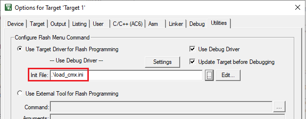
- Switch to the Debug tab, and
click the Settings button.
The configuration settings are different for CMSIS-DAP/ULINK2 and J-Link. Refer to the following sections for the applicable options:
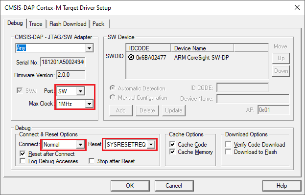
CMSIS-DAP/ULINK2 Target Driver Setup
Use the following options:
- Port: SW
- Max Clock: 1 MHz
- Connect: Normal
- Reset: SYSRESETREQ
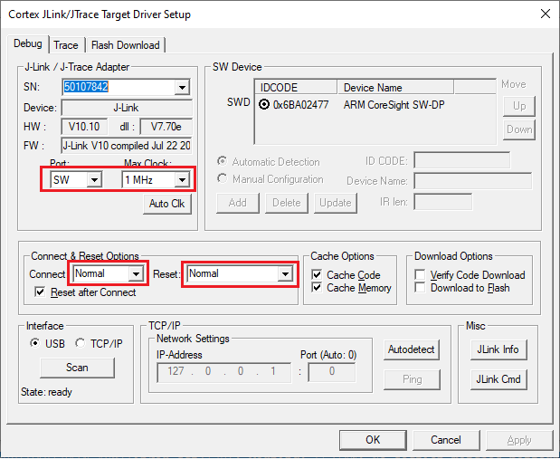
J-Link Target Driver Setup
Use the following options:
- Port: SW
- Max clock: 1 MHz
- Connect: Normal
- Reset: Normal
That completes configuring the CM0+ project. The next step is to configure CM4/CM7 project(s).
Configure CM4/CM7 project
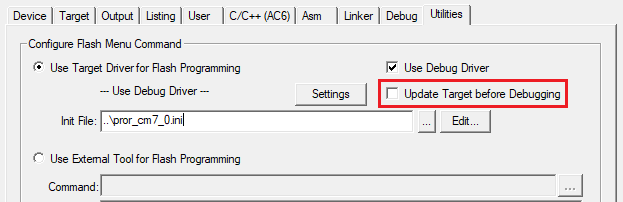
- Open the Options dialog to the Utilities tab, and deselect the Update Target
before the Debugging check box.
- Switch to the Debug tab, select
the applicable debug probe (CMSIS-DAP or J-Link).
- If using ULINK2, select the CMSIS-DAP Debugger option as the debug probe, the ULINK2 driver does not support multi-core debugging.
- Click the Settings button to
configure the target driver.
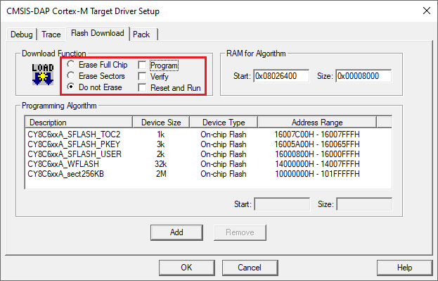
- On the Target Driver Setup dialog, switch to the Flash Download tab, select the Do not Erase radio button, and deselect the Program, Verify, and Reset and Run check boxes.
- Switch to the Debug tab.
The configuration settings are different for CMSIS-DAP/ULINK2 and J-Link. Refer to the following for the appropriate options:
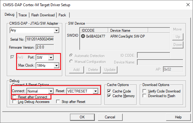
- CMSIS-DAP/ULINK2 Target Driver Setup – Use
the following options:
- Port: SW
- Max Clock: 1 MHz
- Connect: Normal
- Reset: VECTRESET
- Reset after Connect check box: deselected
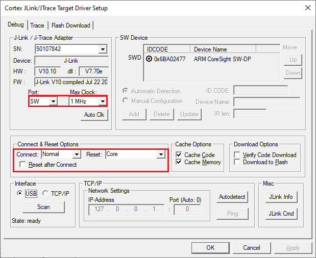
- J-Link Target Driver Setup – Use the
following options:
- Port: SW
- Max Clock: 1 MHz
- Connect: Normal
- Reset: Core
- Reset after Connect check box: deselected
- CMSIS-DAP/ULINK2 Target Driver Setup – Use
the following options:
- Click OK to close the Target
Driver Setup dialog.
- Save the project(s).
Building µVision multi-core projects
Once all projects are open, go ahead and build each one using Project > Build target.
To use J-Link debugger with XMC7000 devices
Program set-up instructions
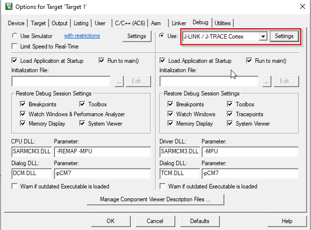
- Select the Debug tab in the
Options for Target dialog, select "J-LINK / J-TRACE Cortex" as the debug adapter, and
click Settings.
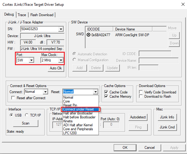
- On the Debug tab in the Cortex
J-Link/JTrace Target Driver Setup dialog, select "SW" for Port, 2 MHz for Max Clock, and
"Connect under Reset" on the Reset pull-down
menu, and then click OK.
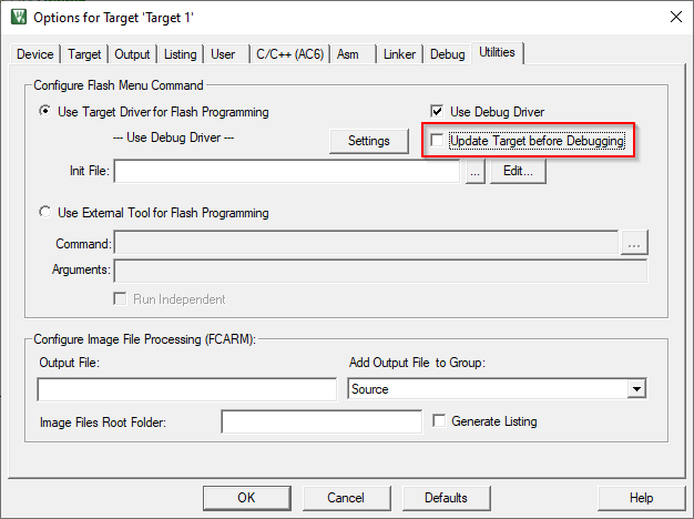
- Select the Utilities tab in the
Options for Target dialog and deselect the Update target
before Debugging check box.
Debug set-up instructions
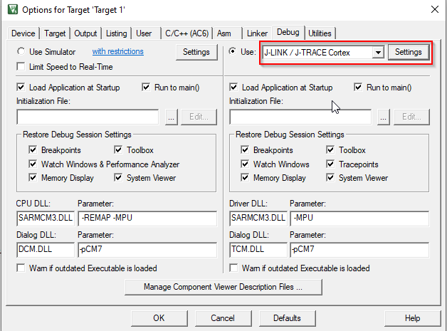
- Select the Debug tab in the
Options for Target dialog, select "J-LINK / J-TRACE Cortex" as the debug adapter, and
click Settings.
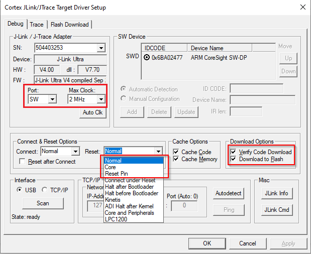
- On the Debug tab in the Target
Driver Setup dialog:
- Port: select "SW"
- Max Clock: select 2 MHz
- Reset pull-down: select "Normal," "Core" or "Reset Pin"
- Download Options: enable "Verify Code Download" and "Download to Flash"
Launch multi-core debug session
To launch a multi-core debug session, all your µVision projects must be opened in separate IDE instances.
- Open a µVision IDE session with the project for the CM0+ core and start
debugging by pressing Debug > Start/Stop Debug
Session. This will program all images, reset the target, and halt at
the beginning of the CM0+ project
main(). - Repeat the same process for the CM4/CM7 core(s). This will attach the running CM4/CM7 core that will be spinning in the boot code until the CM0+ project starts it.
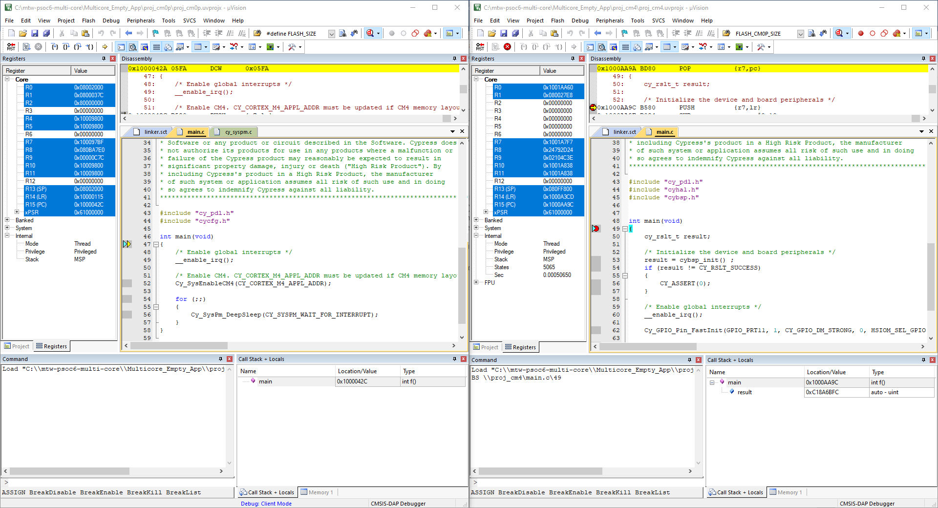
The left side of the screen shows a µVision IDE instance attached to the
CM0+ core. The right side shows the CM4 core has not started yet. Once the
Cy_SysEnableCM4() function on the CM0+ core has been
executed, the CM4 will start executing its application. You can step through the code by
switching back and forth between the two µVision IDE instances.