- Erase device
- Program device
- Program device and Reset Chip
- Program binary file with Offset
- Program External Memory
- Program PSOC™ 6/Control C3/Edge E84 MCU in JTAG chain via KitProg3/MiniProg4
- Program PSOC™ 6/Control C3/Edge E84 MCU in JTAG chain via J-Link probe
- Verify device
- Verify device with External Memory
- Verify custom flash regions
- Read device
- Program eFuse region of PSOC™ 6/TRAVEO™ T2G/XMC7xxx/XMC5xxx MCU
- Program chip-protected/Kill Mode for PSOC™ 4 MCU
- Program secure AIROC™ CYW20829 MCU
- Program secure PSC3/PSE84 MCUs via J-Link hardware programmer
- Program QSPI memory with patched flashloader via KitProg3/MiniProg4
- Program QSPI memory with patched flashloader via J-Link probe
- Program AIROC™ CYW955513EVK-01, CYW955913EVK-01, and CYW9M2BASE-43012BT boards
- Update KitProg3 Board Name
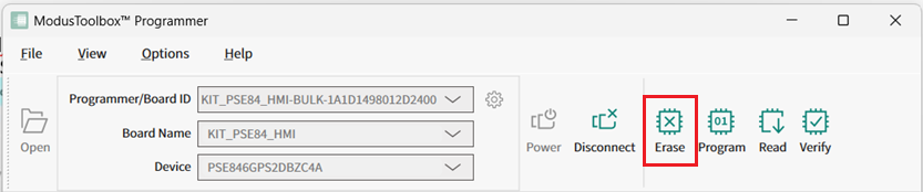
Erase device
- Connect to the device (see Connect device).
- Click the Erase button.
Program device
- Connect the device to the host computer and select it in the Programmer/Board ID, Board Name, and Device drop-downs.
- Select the programming file as described in Load programming file section.
- Connect to the device (see Connect device).
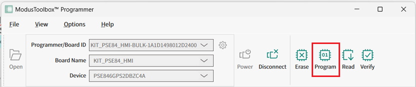
- Click the Program button.
Program device and Reset Chip
- Connect the device to the host computer and select it in the Programmer/Board ID, Board Name, and Device drop-downs.
- Select the programming file as described in the Load programming file section.
- Connect to the device (see Connect device).
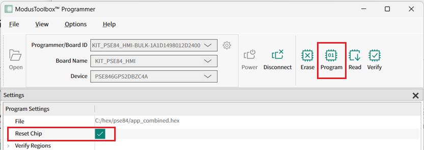
- Select the Reset Chip check box under Program Settings.
- Click the Program button.
The target device is reset and running.
Program binary file with Offset
- Connect the device to the host computer and select it in the Programmer/Board ID, Board Name, and Device drop-downs.
- Select a binary programming file as described in the Load programming file section.
- Connect to the device (see Connect device).
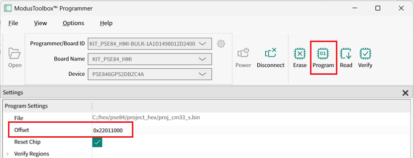
- Enter the desired address in the Offset field under Program Settings.
- Click the Program button.
Program External Memory
- Attach and select a device that supports external memory (for example, CY8CKIT-062-WiFi-BT with QSPI support).
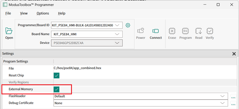
- Select the External Memory option
under Program Settings.
- Select the programming file as described in the Load programming file section. The programming file should contain external memory region(s) and correct QSPI configuration data.
- For PSOC™ 6 devices only, select Erase/Program USER/TOC/KEY allowed option under Probe Settings > Sflash Restrictions.
- Connect to the device (see Connect device).
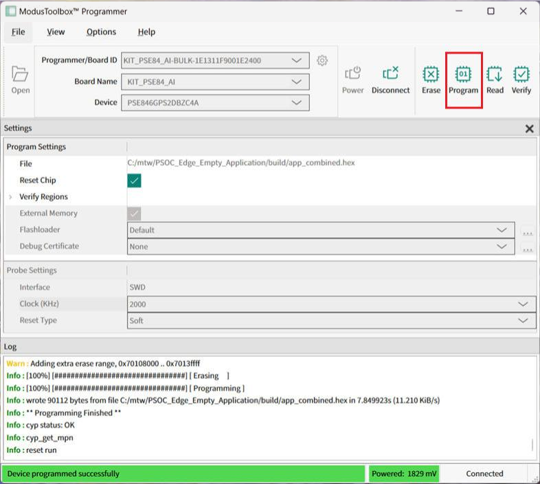
- Click the Program button.
Program PSOC™ 6/Control C3/Edge E84 MCU in JTAG chain via KitProg3/MiniProg4
- Connect the host computer to a MiniProg4 probe attached to several MCU
targets in the JTAG chain.The following hardware configuration is used in this example:
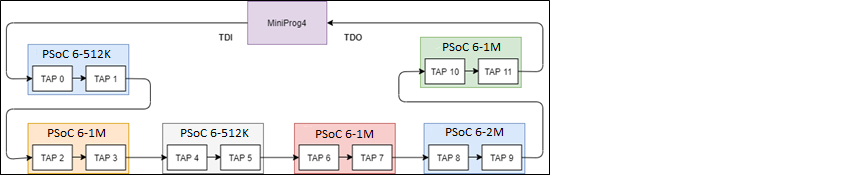
The sample JTAG chain configuration contains six serially-connected PSOC™ MCU targets.
- Select the MiniProg4 probe and target device in the Programmer/Board ID, Board Name, and Device drop-downs, and ModusToolbox™ Programmer will display information under Probe Settings. Ensure the JTAG chain is powered.
- Select the JTAG interface in the Interface drop-down.
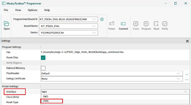 ModusToolbox™ Programmer queries the JTAG chain and displays detected devices under the JTAG Chain option in Probe Settings. The list of devices in the chain contains target names for supported devices and ID codes for those which are not supported.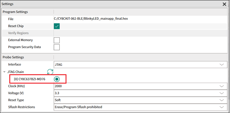
- Select the desired target device in the list by clicking the radio button next to the target name.
- Select the programming file as described in the Load programming file section.
- Click Connect. ModusToolbox™
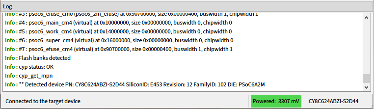
Programmer communicates with the device and displays various messages in the Log. Then, a message in the Status Bar indicates that it
is connected.
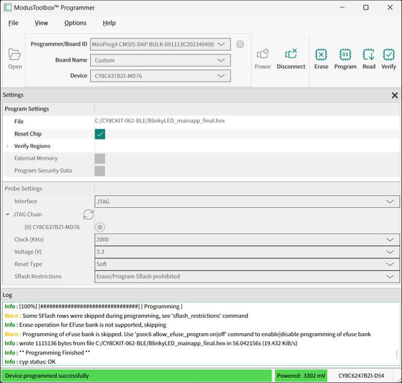
- Click the Program button.
Program PSOC™ 6/Control C3/Edge E84 MCU in JTAG chain via J-Link probe
- Connect the host computer to a J-Link probe attached to several MCU targets in the JTAG chain. Ensure all connected targets support JTAG interface.
- Select the J-Link probe and target device in the Programmer/Board ID, Board Name, and Device drop-downs, and ModusToolbox™ Programmer will display information under Probe Settings. Ensure the JTAG chain is powered.
- Select the JTAG interface in the Interface drop-down. ModusToolbox™ Programmer
queries the JTAG chain and displays detected devices under the JTAG Chain option in
Probe Settings. The list of devices in the chain contains target names for supported
devices and ID codes for those which are not supported.
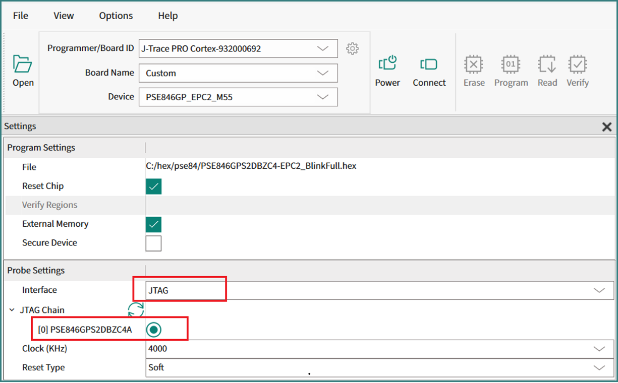
- Select the desired target device in the list by clicking the radio button next to the target name.
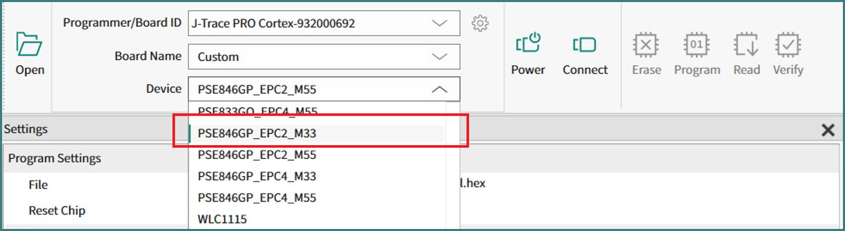
- Additionally select the desired target name in Device
drop-down.
- Select the programming file as described in the Load programming file section.
- Click Connect. ModusToolbox™ Programmer communicates with the device and displays various messages in the Log.
- Click the Program button.
Verify device
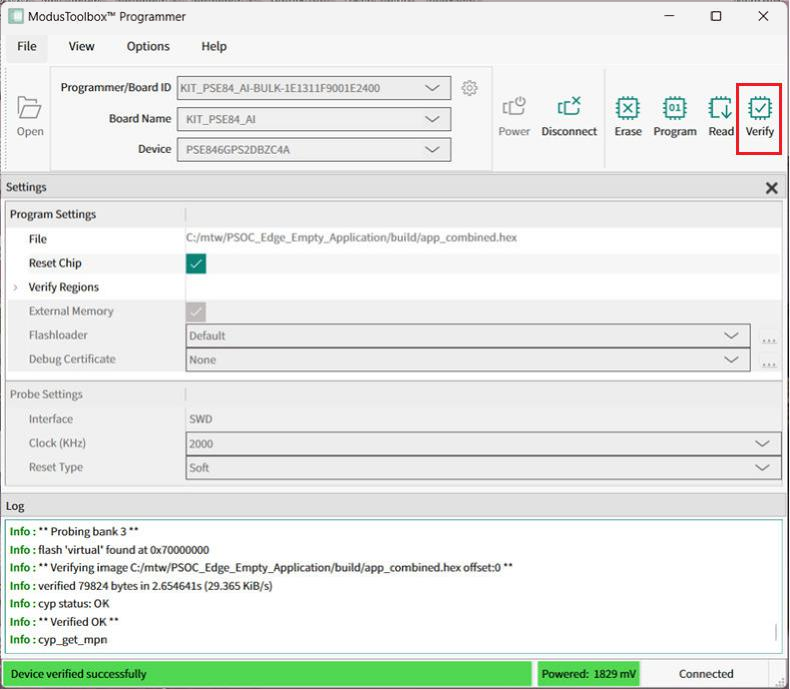
- Connect the device to the host computer and select it in the Programmer/Board ID, Board Name, and Device drop-downs.
- Select the programming file as described in the Load programming file section.
- Connect to the device (see Connect device).
- Click the Verify button.
Verify device with External Memory
- Connect the device that supports external memory (for example, CY8CKIT-062-WiFi-BT with QSPI support) to the host computer and select it in the Programmer/Board ID, Board Name, and Device drop-downs.
- Select the programming file as described in the Load programming file section. The programming file should have external memory region(s).
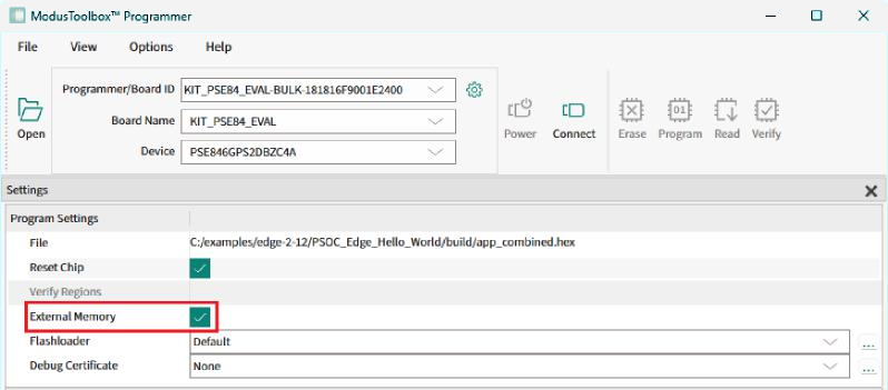
- Select the External Memory option under Program Settings.
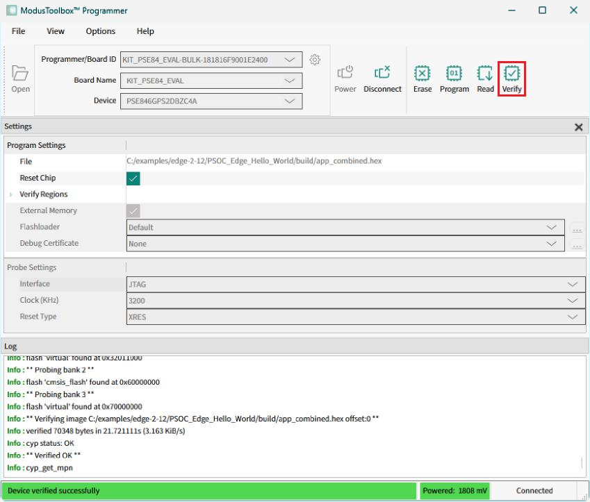
- Connect to the device (see Connect device).
- Click the Verify button.
Verify custom flash regions
- Connect the device to the host computer and select it in the Programmer/Board ID, Board Name, and Device drop-downs.
- Select the programming file as described in the Load programming file section.
- Connect to the device (see Connect device).
- Expand Verify Regions option in Program Settings to see the list of
flash regions available for verification. By default, only supported by target device
regions are displayed:
- application
- AUXflash
- Sflash
- eFuse
- QSPI
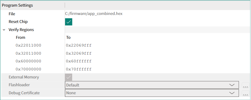
- Right-click on Verify Regions or
any region entry to open the context menu.
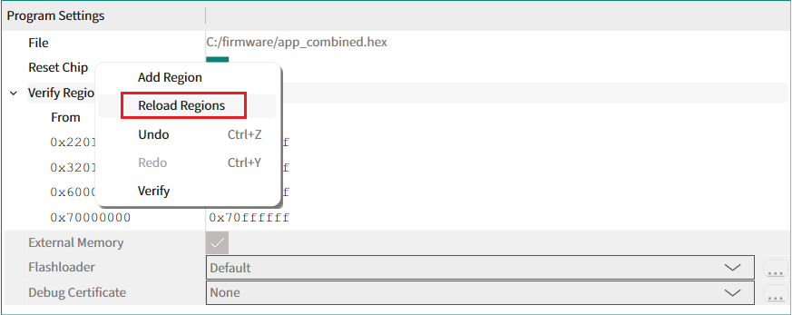
- To add a custom flash region, select Add
Region. Select the added list entry, and enter the correct values for
start and end addresses of the region.

- To remove any region in the list, right-click the desired region entry
and select Remove Region.
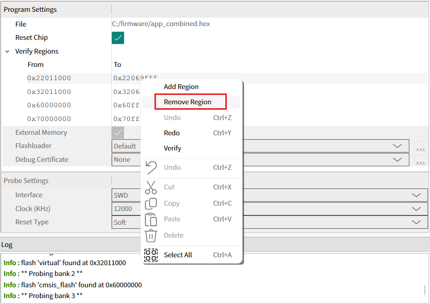
- To revert any previous change, select Undo.
- When finished with the list of regions, start device verification by
clicking the Verify button on the toolbar.
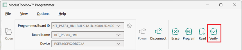 You can also select Verify on the context menu.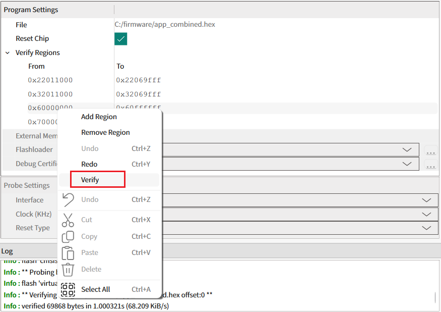
ModusToolbox™ Programmer verifies only the regions specified in the Verify Regions list. Then, a message in the Status Bar indicates that the device was verified successfully or that an error occurred.
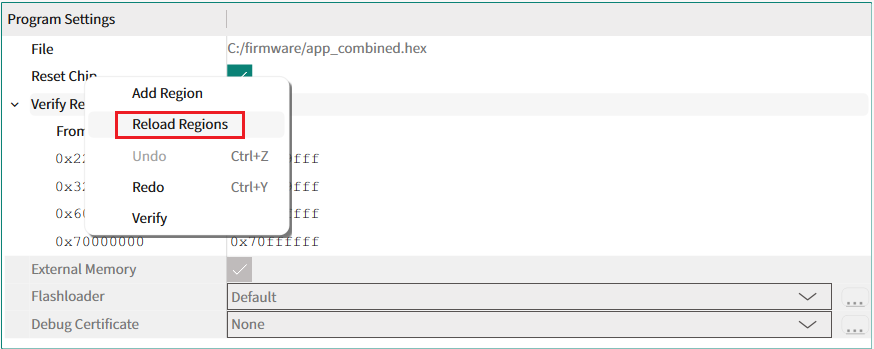
- To reset the Verify Regions list
to its default state select Reload Regions from
the context menu. This action will remove all custom regions and load default regions
corresponding to the flash map.
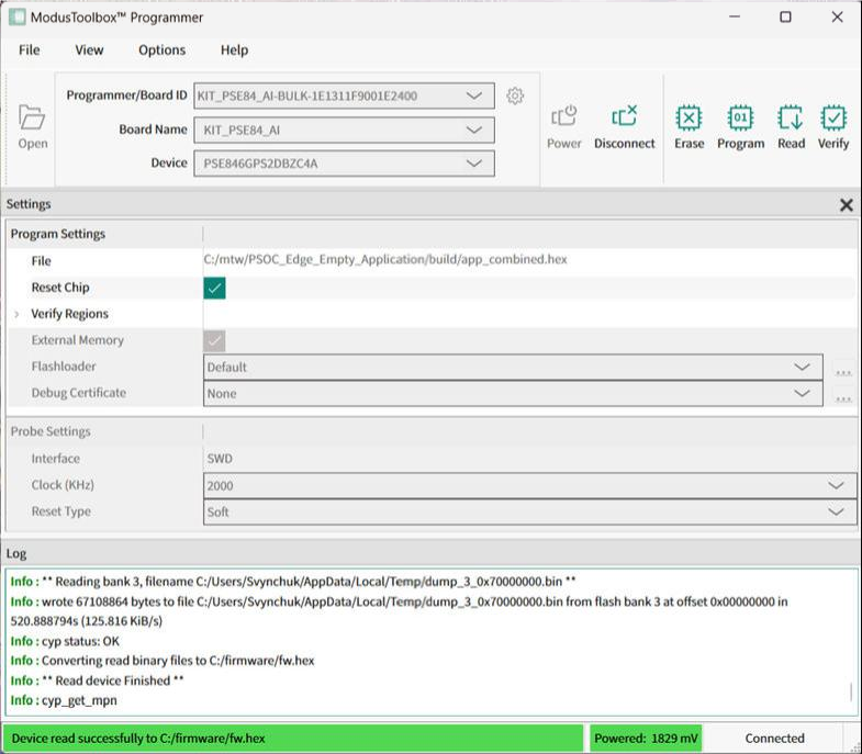
Read device
- Connect the device to the host computer and select it in the Programmer/Board ID, Board Name, and Device drop-downs.
- Connect to the device (see Connect device).
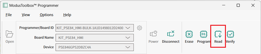
- Click the Read button.
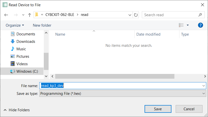
- On the Read Device to File dialog, navigate to the location of the HEX
or SREC file to be saved, enter the file name, select the file type in the Save as type drop-down, and click Save.
Program eFuse region of PSOC™ 6/TRAVEO™ T2G/XMC7xxx/XMC5xxx MCU
- Connect the device to the host computer and select it in the Programmer/Board ID, Board Name, and Device drop-downs.
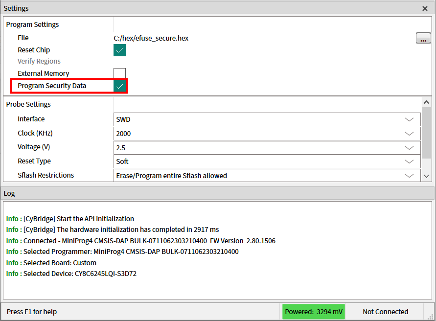
- Select the programming file as described in the Load programming file section. The programming file should contain valid eFuse data region (at address 0x90700000).
- Select the Program Security Data
check box under Program Settings.
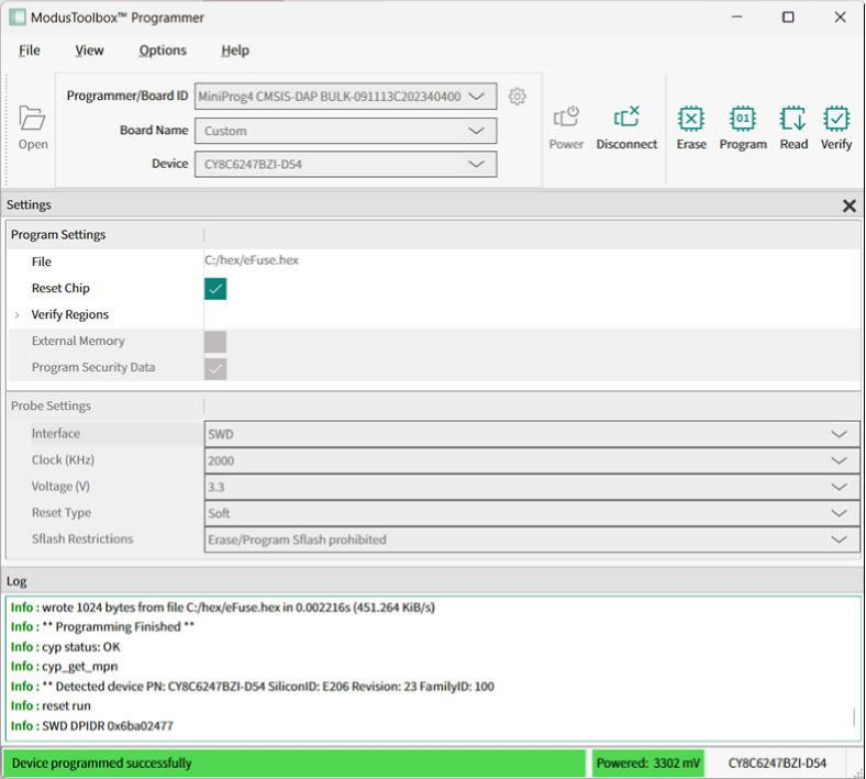
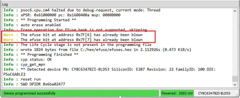
- Connect to the device (see Connect device).
- Click the Program button.
Program chip-protected/Kill Mode for PSOC™ 4 MCU
The chip-level protection mechanism restricts access of the programmer application to silicon resources. In this mode, access to flash, SRAM, and most of the registers in the PSOC™ 4, PMG1, PAG2s, and CCGx are disabled.
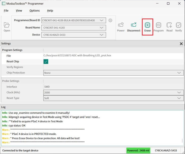
Use the Erase button to clear chip protection and move target to the open state.
Switch to Protected mode
- Connect the device to the host computer and select it in the Programmer/Board ID, Board Name, and Device drop-downs.
- Select the Chip
Protection pull-down and select Protected mode.A warning message asking for confirmation is displays.
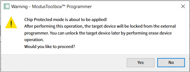
- Click Yes to apply Protected mode for your PSOC™ 4, PMG1, PAG2S and CCGx.
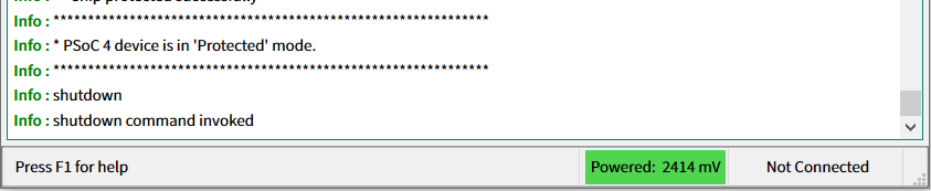
When the operation completes, the log is appended with a message, and the device is disconnected from the programmer automatically.
Switch to Kill mode
- Connect the device to the host computer and select it in the Programmer/Board ID, Board Name, and Device drop-downs.
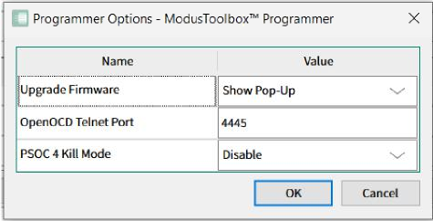
- To use Kill mode, go to Options > Programmer
Options and enable it in PSOC 4 Kill
Mode drop-down.
- Connect to the device (see Connect Device).
- Click the Chip Protection pull-down
and select Kill mode.A warning message asking for confirmation is displays.
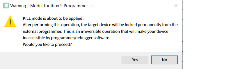
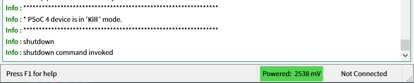
- Click Yes to apply Kill mode for your PSOC™ 4, PMG1, PAG2S and CCGx.
Program secure AIROC™ CYW20829 MCU
You can program the flash of an AIROC™ CYW20829 device in Secure lifecycle mode only by providing a valid debug certificate file.
- Connect the device to the host computer and select it in the Programmer/Board ID, Board Name, and Device drop-downs.
- Select the programming file as described in the Load programming file section.
- Click on the Debug Certificate
option under Program Settings and select the
certificate file in the dialog.The path will display under Settings.
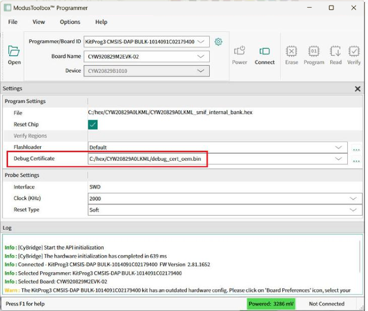
- Connect to the device (see Connect device).
- Click the Program button.
Program secure PSC3/PSE84 MCUs via J-Link hardware programmer
The Infineon PSOC™ Control C3 and PSOC™ Edge E8 series support secure debug/programming by using AP access authentication with a signed debug token. PSOC™ Control and PSOC™ Edge AP access authentication is implemented in appropriate “.pex” script files. Full information about the secure flow can be found on these webpages:
https://kb.segger.com/Infineon_PSOC_Control_C3_Debug_Port_Authentication
https://kb.segger.com/Infineon_PSoC_Edge_E8_Debug_Port_Authentication
PSOC™ Control C3 secure program flow
- Connect PSOC™ Control C3 kit with target in Secure lifecycle.
- Go to the Segger software tools installation folder; for example , C:\Program Files\SEGGER\JLink_V958.
- Perform AP access authentication by uploading the debug token and letting BootROM enable the CM33 AP.
- Run the DevPro command from a terminal passing the path to Debug certificate via the
DebugCertFileparam:DevPro.exe -operation DebugAccessPortAuth -SetConfigVal DebugCertFile="c:/tmp/debug_token.bin" -SetConfigVal DebugCertKeyType=OEM_ROT -ScriptFile "PCode_DevPro_Infineon_PSC3_DebugAuth.pex" -if SWD -speed 1000Output example:
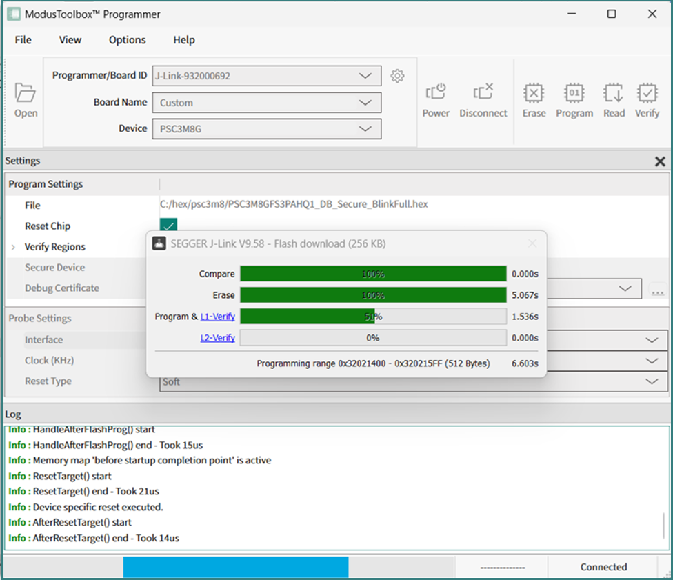
SEGGER Device Provisioner V9.58 Compiled Jul 9 2026 15:58:54 Command line: -operation DebugAccessPortAuth -SetConfigVal DebugCertFile=c:/tmp/debug_token.bin -SetConfigVal DebugCertKeyType=OEM_ROT -ScriptFile PCode_DevPro_Infineon_PSC3_DebugAuth.pex -if SWD -speed 1000 Firmware: J-Trace PRO V2 Cortex compiled Dec 4 2024 17:58:20 S/N: 932000692 J-Link log: CM33 AP is closed. J-Link log: Debug certificate has been uploaded to the target J-Link log: Token validation is successful J-Link log: CM33 AP become available J-Link log: AP access authentication succeededNote:The “AP access authentication succeeded” log message is displayed on success. - Run mtb-programmer, select your PSOC™ Control C3 device, select the programming file and
click on Secure Device check box:
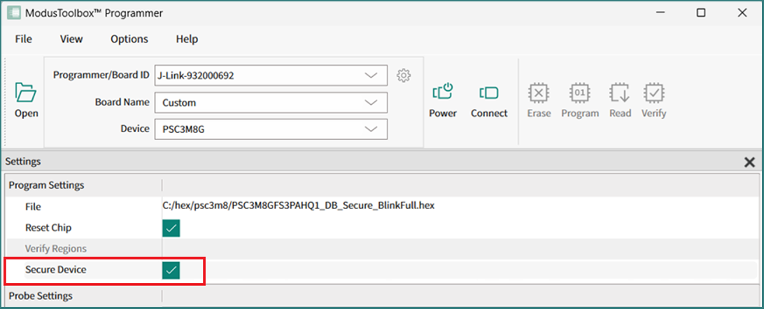
- Press Connect and Program.
PSOC™ Edge E8 secure program flow
- Connect PSoC Edge E8 kit with target in Secure lifecycle.
- Go to the Segger software tools installation folder; for example, C:\Program Files\SEGGER\JLink_V958.
- Perform AP access authentication by uploading the debug token and letting BootROM enable the CM33 AP.
- Run the DevPro command from terminal passing the path to Debug certificate via the
DebugCertFileparam:DevPro.exe -operation DebugAccessPortAuth -SetConfigVal DebugCertFile="c:/tmp/debug_token.bin" -SetConfigVal DebugCertKeyType=OEM_ROT -ScriptFile "PCode_DevPro_Infineon_PSoC_E8_DebugAuth.pex" -if SWD -speed 1000 - Ensure the AP access authentication succeeded message present in logs.
- Follow same steps 5-6 from PSOC™ Control C3 secure program flow.
Program QSPI memory with patched flashloader via KitProg3/MiniProg4
This feature is supported by AIROC™ CYW20829 devices, as well as PSOC™ Edge E84, XMC7100/7200 and CYT4Bx MCUs. It allows you to specify the patched flashloader file in FLM format along with the appropriate QSPI configuration. Patched flashloaders contain data about how your external memory is configured.
- Connect the device to the host computer and select it in the Programmer/Board ID, Board Name, and Device drop-downs.
- Select the programming file as described in the Load programming file section.
- Select the External Memory option under Program Settings (if supported).
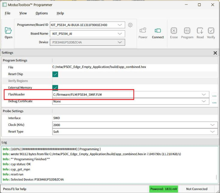
- Click on the Flashloader option
under Program Settings and select the
patched flashloader (FLM) file in the dialog.The path will display under Settings.
- Connect to the device (see Connect device).
- Click the Program button.
Refer to the QSPI Configurator user guide for more information about patching flashloaders.
Program QSPI memory with patched flashloader via J-Link probe
This procedure is based on the SEGGER "J-Link Device Support Kit" article (https://kb.segger.com/J-Link_Device_Support_Kit). It lets you supply a custom flashloader for your specific external QSPI flash and program it through a J-Link probe. As an example, we program the external Octal-SPI flash on the PSOC™ Edge E84 Evaluation Kit.
- Locate the JLinkDevices folder on your system as described in the "JLinkDevices folder" section of the "J-Link Device Support Kit" article. Create it if it does not exist.
- Go to the mtb-programmer install location (on Windows:
C:\Infineon\Tools\ModusToolboxProgtools-2.0\mtb-programmer) and copy the
flashloader scripts\CAT1D\PSE84_OCTAL_DDR_SFDP_SMIF.FLM into the
JLinkDevices folder.Note:The Loader path in the XML below is resolved relative to the XML file. Keep the .FLM file in the same folder as the XML you create in step 3.
- In the JLinkDevices folder, create a new XML file (for example,
Devices.xml) and define a new device that inherits from the base
PSE846GP_EPC2_M33 device and overrides its SMIF flash banks with the custom loader,
as described in the "Adding a flash loader" section of the
article:
<DataBase> <Device InheritFrom="PSE846GP_EPC2_M33"> <ChipInfo Vendor="Infineon" Name="PSE846GP_EPC2_M33_octal_sfdp"/> <FlashBankInfo Name="SMIF0_NS" BaseAddr="0x60000000" MaxSize="0x08000000" Loader="PSE84_OCTAL_DDR_SFDP_SMIF.FLM" LoaderType="FLASH_ALGO_TYPE_CMSIS" AlwaysPresent="0" /> <FlashBankInfo Name="SMIF0_S" BaseAddr="0x70000000" MaxSize="0x08000000" Loader="PSE84_OCTAL_DDR_SFDP_SMIF.FLM" LoaderType="FLASH_ALGO_TYPE_CMSIS" AlwaysPresent="0" /> </Device> </DataBase>Note:0x60000000 (non-secure) and 0x70000000 (secure) are two address views of the same physical device. Set MaxSize to at least the size of the region you program. For the 1 Gbit (128 MByte) part in this example, use 0x08000000; adjust it to match your flash. - Connect the J-Link probe and the PSE84 target to the host, start
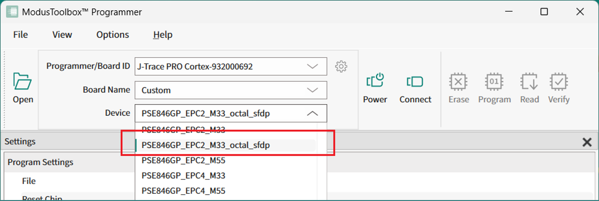
mtb-programmer, select the J-Link probe, and choose the newly created
PSE846GP_EPC2_M33_octal_sfdp device in the Device drop-down.
- Select the programming file as described in the Load programming file section.
- Under Program Settings, enable the External Memory option.
- Click Connect, then click Program.
Program AIROC™ CYW955513EVK-01, CYW955913EVK-01, and CYW9M2BASE-43012BT boards
- Connect the device to the host computer and perform recover device procedure as described in How to recover AIROC™ Bluetooth® devices on failure.
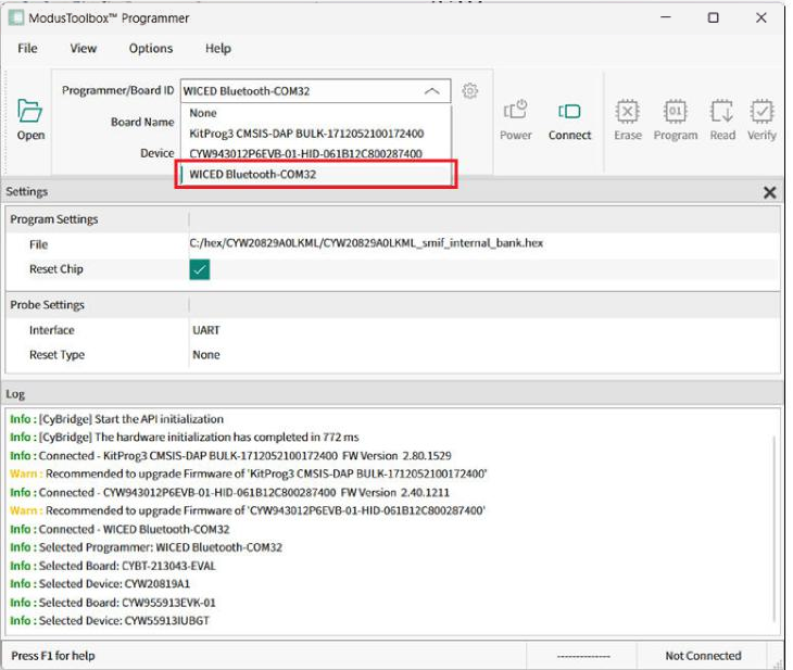
- Click the Programmer pull-down and select 'WICED Bluetooth-PortXX'
programmer.
 Note:The CYW9M2BASE-43012BT board should be switched to Dual UART mode first, otherwise the WICED Bluetooth® programmer will be unavailable in the Board Name pull-down menu. To do this, press the hardware 'Mode' button on the Kit, hold it for 3 seconds, then release it.
 - Open the Board Name pull-down and select the appropriate board name (e.g., CYW955513EVK-01)
- Select the programming file as described in the Load programming file section.
- Connect to the device (see Connect device).
- Click the Program button.
ModusToolbox™ Programmer programs the device and displays various messages in the Log. Then, a message in the Status Bar indicates that the device was programmed successfully or that an error occurred.
Update KitProg3 Board Name
Some KitProg3 development kits were released to market with missing board configuration in the EEPROM. In this case, the Programmer/Board ID displays the kit as generic KitProg3 device as:
KitProg3 CMSIS-DAP Bulk-1014091C02179400
Some development kits may require updating the name of the board after changing SOM modules on them for example:
KIT_PSE84_EVAL_EPC2 (EPC4).
- Click on the Board Preferences button to update the name of your kit. The Board Preferences dialog opens.
- As needed, click on the Show all boards
check box to display the full list of supported names.
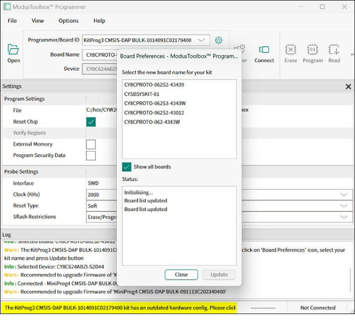
- Select the correct board name for your kit in the list and click the
Update button.
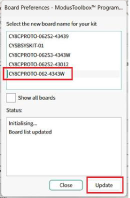 The tool checks if the selected name corresponds to the actual connected KitProg3 device. Board configuration is updated in the EEPROM of KitProg3. The success status and a new board name are displayed.
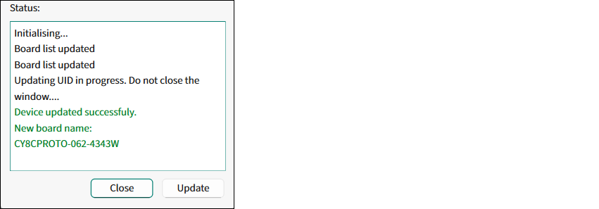 Note:The “Device not updated” error means an incorrect kit name was selected.
 - Click the Close button, the dialog closes and the updated board name
displays in the pull-downs.
