The Display view contains one or more tabs that show display types
configured in the Display Editor.
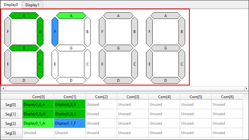
A display symbol contains a set of pixels named A, B, C… (or 00, 01, 02 for the matrix display type) by default. The pixel names correspond to cell names in the Mapping table (for a pixel placed on the mapping table). The pixels have colors showing the connectivity status:
- Light Green – The pixel is connected, and the symbol is currently selected.
- Dark Green – The pixel is connected, and the symbol is currently not selected.
- Blue – The pixel is currently selected (connected or not).
- White – The pixel is not connected, and the symbol is currently selected.
- Grey – The pixel is not connected, and the symbol is not currently selected.
Note:
The same colors are used for pixels in the mapping table, when applicable.
Note:
In this document, symbol segments for displays (for example, 7-segment, 14-segment,
etc.), are called “pixels” so that they are not confused with segment LCD connections
(physical wires) represented as rows of the mapping table (see Abbreviations and
definitions under About this document).