About this document
A newer revision of this document may be available on the web here.
Scope and purpose
The Device Firmware Update (DFU) Host tool is a stand-alone program included with the ModusToolbox™ software. This tool is used to communicate with PSOC™ 6, PSOC™ 4, PSOC™ Edge, PSOC™ Control, and XMC™7000 MCUs that have already been programmed with an application that includes the DFU capability.
Intended audience
This document helps application developers understand how to use the DFU Host tool as part of creating a ModusToolbox™ application.
Document conventions
| Convention | Explanation |
|---|---|
|
Bold |
Emphasizes heading levels, column headings, menus and sub-menus |
|
Italics |
Denotes file names and paths. |
|
|
Denotes APIs, functions, interrupt handlers, events, data types, error handlers, file/folder names, directories, command line inputs, code snippets |
|
File > New |
Indicates that a cascading sub-menu opens when you select a menu item |
Abbreviations and definitions
The following define the abbreviations and terms used in this document:
- Application – One or more projects related to each other.
- CAN-FD – controller area network-flexible data rate
- I2C – inter-integrated circuit
- PEC – packet error code
- PMBus – power management bus (PMBus®)
- PSOC™ – programmable system-on-chip
- SPI – serial peripheral interface
- UART – universal asynchronous transmitter receiver
- UART-CDC – UART-communication device class
- USB-HID – universal serial-bus-human interface device
Reference documents
Refer to the following documents for more information as needed:
Overview
The DFU Host tool is a cross platform utility for managing DFU firmware upgrades. The tool has both GUI and CLI interfaces.
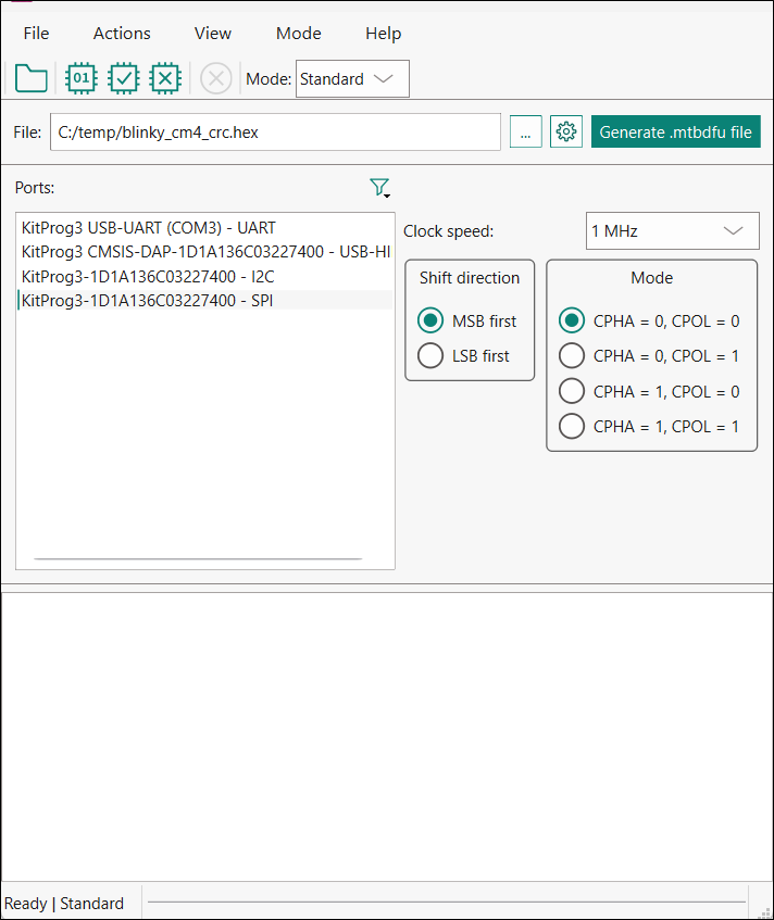
This tool allows you to:
- Program new application data onto the supported MCU device using supported input files. See Supported devices and file formats.
- Verify the program data that is already contained on the device.
- Erase the application from the device.
- Select the *.mtbdfu file output from a ModusToolbox™ application in order to program, write, read, erase and communicate with the device.
- Abort the current operation.Note:This operation leaves the device in whatever state it is in when the abort message is acted upon.
The DFU Host tool supports communicating via I2C, SPI, UART, USB-CDC, USB-HID, and CAN-FD. They are displayed to configure their settings and view the programming status. For I2C and SPI, supported MCU should include the KitProg3 firmware module or other bridge interface, which implements USB-UART, USB-I2C, and USB-SPI bridges. For UART, communication can be done directly from the PC simply by connecting an appropriate cable. For CAN-FD, PEAK System hardware must be used.
Supported devices and file formats
All MCUs can be used with the all files formats.
| Device | File format | Link | |||
|---|---|---|---|---|---|
|
MCU |
*.mtbdfu |
*.hex |
*.bin |
*.cyacd2 |
|
|
PSOC™ 6 |
Y |
Y |
Y |
Y |
|
|
PSOC™ 4 |
Y |
Y |
Y |
Y |
|
|
XMC7000 |
Y |
Y |
X |
X |
|
|
PSOC™ Edge |
Y |
Y |
X |
X |
|
| PSOC™ Control | Y | Y |
X |
X | |
Example code
The source code for the DFU Host tool is provided in the installation directory:
- Windows: ~/ModusToolbox/tools_<version>/dfuh-tool/sample_code
- Linux™: /opt/Tools/ModusToolbox/tools_<version>/dfuh-tool/share/dfuh-tool/sample_code/
- macOS: /Applications/ModusToolbox/tools_<version>/dfuh-tool/dfuh-tool.app/Contents/sample_code/
Use this source code as a reference to build your own tool. Refer to the README.md file for instructions on how to install the required dependencies and build the DFU Host Tool.
Quick start
This section contains a simple workflow for how to use the DFU Host tool.
- Ensure that you have a supported MCU that has been programmed with an application that includes the DFU capability.
- Launch the DFU Host tool.
- Click File > Open to browse to the location of your application file: *.cyacd2, *.mtbdfu, *.hex or *.bin).
- Connect the device with an application that includes the DFU capability.
- Wire the hardware port pins to the corresponding pins on the target device.
- Update the Port configuration. These values are set from the communication component used by the bootloader component.
- Click Program/Execute to load the new application from *.bin, *.cyacd2 or *.hex file and to execute and send the commands from the .*mtbdfu file.
Drivers Installation
- Windows: https://www.peak-system.com/quick/DrvSetup
- Linux: https://www.peak-system.com/quick/PCAN-Linux-Driver
- macOS: https://github.com/mac-can/PCBUSB-Library/releases/download/v0.13/macOS_Library_for_PCANUSB_v0.13.tar.gz (After installing the library, rename it to libPCBUSB.dylib and copy it into the .../dfuh-tool/dfuh-tool.app/Contents/Frameworks folder.)
Launch the DFU Host tool
There are several ways to launch the DFU Host tool, and those ways depend on how you use the various tools in ModusToolbox™ software.
VS Code and Eclipse
VS Code and Eclipse have tools to launch the DFU Host tool from within an open application. Refer to the applicable user guide for more details:
Executable (GUI)
You can launch the DFU Host tool as a stand-alone tool without the Eclipse IDE. By default, it is installed here:
- Windows: ~/ModusToolbox/tools_<version>/dfuh-tool/
- Linux™: /opt/Tools/ModusToolbox/tools_<version>/dfuh-tool/bin/
- macOS: /Applications/ModusToolbox/tools_<version>/dfuh-tool/
On Windows, you can launch the tool from the Start menu. For other operating systems, the installation directory will vary, based on how the software was installed.
Executable (CLI)
Refer to CLI description to run the dfuh-cli tool. You can also run the DFU Host tool GUI executable using the following command line arguments:
| Argument | Description |
|---|---|
|
|
Displays information on valid command-line arguments and exits.. |
|
|
Displays help including Qt-specific options. |
|
|
Displays the version information. |
|
|
Appends logging information to the specified file. |
GUI description
Menus
File
- Open… – Opens an existing input file of the supported formats. If a file is already open, it will be closed.
- Save Log As… – Opens the dialog to save the log file in a specified location.
- Clear Log – Clears the current log.
- Exit – Closes the DFU Host tool.
Actions
- Program – Programs the application to the device.
- Execute – Executes the .mtbdfu file on the host, establishes a DFU session with the target and processes the DFU commands
- Verify – Verifies the programming of the device.
- Erase All – Erases the program from the device.
- Abort – Aborts the action.
View
- Toolbar – Shows/hides the toolbar.
- Standard – Communicates directly with the target device (default).
- Bridging – Communicates with a companion device through a bridge MCU.
Help
- View Help – Opens this document.
- About Device Firmware Update Host Tool – Opens the About box for version information, with links to open https://www.infineon.com and the current session log file.
Main window
File selection
This section describes how to select the input file, which contains the DFU commands or firmware image.
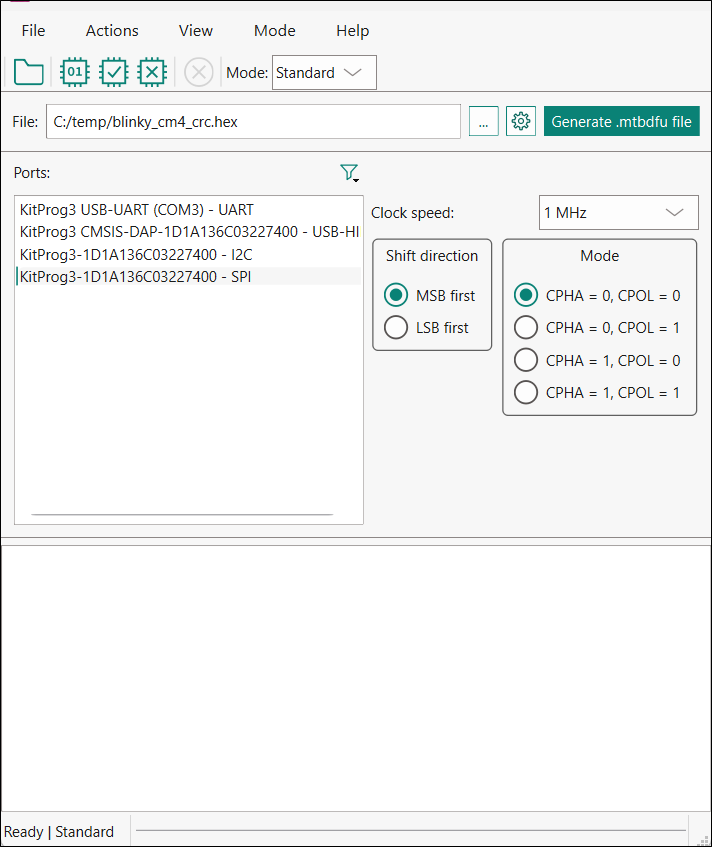
* .mtbdfu file configuration
The Configure and Generate buttons display when one or more *.bin or *.hex files are passed as an input. Click the Configure button to display the "Configuration" window.
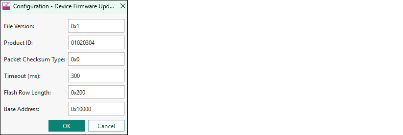
Enter the .mtbdfu file parameters to generate an *.mtbdfu file that is used to program/verify/erase the selected *.hex or *.bin file.
Ports
This section lists all ports attached to the computer to communicate with the bootloader. Based on which item is selected, different options are available for the Port Configuration.
Filters
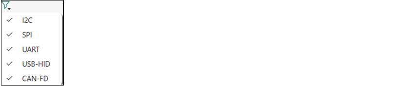
Use the Filters button to select which ports display in the Ports list.
Configure Companion
The Configure Companion button displays in the main window when Bridging mode is selected. Click the Configure Companion button to display the "Configure Companion" window

Enter the companion device parameters to configure the connection between the host and companion devices.
- Interface – Select the companion communication interface. The supported interfaces are I2C and UART.
- Device ID – Enter the companion device ID. For I2C, the valid range is 8 to 120 (0x08 to 0x78).
Port configuration
This section allows for configuring the interface-specific options for communicating with the DFU system. This is necessary to ensure both the DFU and host computer are configured the same.
Refer to the appropriate probe documentation for a list of supported modes.
I2C

The parameters for the I2C communication:
- Address – The address of the I2C-based target DFU system with which the host is communicating. The range for valid addresses is 8 - 120.
- Speed – The I2C SCK signal frequency.
Note: It may happen that the device sends neither ACK nor NACK signal. In this case, it may take the DFU Host tool up to 20 seconds to send a "timeout" error.
PMBus

The parameters for the PMBus communication:
- Command code – The PMBus command byte to send to the device.
- Command size – The number of data bytes associated with the PMBus command.
- Use PEC byte – Check this to append/verify the PMBus PEC for data integrity.
SPI
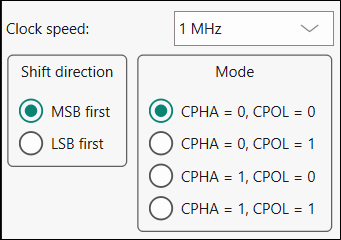
The parameters for the SPI communication:
- Clock speed – The SPI SCLK signal frequency.
- Shift direction – The bit ordering of transferred data.
- Mode – The SPI operating mode.
UART and USB-CDC

The parameters for the UART/USB-CDC communication:
- Baud – The baud (bit) rate at which data is transferred.
- Data bits – The number of data bits per byte.
- Stop bits – The number of stop bits indicating the termination of a byte.
- Parity – The parity bit added to a byte.
Note: KitProg3 and MiniProg devices do not support custom values for data bits, stop bits, and parity. They are set to 8 data bits, 1 stop bit, and no parity respectively and cannot be changed.
USB-HID
USB-HID does not need port configuration. Both VID and PID are obtained automatically the device name is selected.
CAN-FD
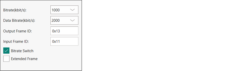
The parameters for the CAN-FD communication:
- Bitrate – The bitrate in kbit/s at which data is transferred.
- Data bitrate – The data bitrate in kbit/s at which data is transferred if bitrate switch is enabled.
- Output Frame ID – The output Frame ID for each sent frame.
- Input Frame ID – Optional. Filters an incoming CAN-FD frame by its frame ID. Leave this field empty if you do not use it.
- Bitrate Switch – The bitrate switch to enable switching between bitrate and data bitrate.
- Extended Frame – Extended Frame to enable extended frame support.
|
Nominal Bitrate (kbps) |
Data Bitrate (kbps) |
|||||||
|---|---|---|---|---|---|---|---|---|
| 125 | 250 | 500 | 1000 | 2000 | 4000 | 8000 | 10000 | |
|
Clock Frequency (Mhz) |
80 | 80 | 80 | 80 | 80 | 80 | 80 | 80 |
|
Prescaler |
40 | 20 | 10 | 10 | 4 | 2 | 2 | 1 |
|
Time Segment 1 |
12 | 12 | 12 | 5 | 7 | 7 | 7 | 5 |
|
Time Segment 2 |
3 | 3 | 3 | 2 | 2 | 2 | 2 | 2 |
|
Synchronization Jump Width |
1 | 1 | 1 | 1 | 1 | 1 | 1 | 1 |
Log
The log displays the history of what happened while the host was open:
- when operations started/completed
- information about user-initiated operations
- error messages during an operation if any.
Errors
Any errors for various fields display as a red X in the field containing the relevant error, and it contains a tooltip when you hover the mouse cursor on it.
CLI description
In addition to the dfuh-tool GUI executable, there is also the dfuh-cli executable. The CLI allows programming, verifying, and erasing devices from a command-line prompt or from within batch files or shell scripts. The exit code for the dfuh-cli executable is zero if the operation is successful, or non-zero if the operation encounters an error.
To use the dfuh-cli executable, provide one of the following flags:
| Flag | Description |
|---|---|
|
|
Programs the device with the specified file and exits. |
|
|
Verifies the programming of the device with the specified file and exits. |
|
|
Erases the specified program from the device and exits. |
|
|
Executes commands defined in the specified *.mtbdfu file (JSON format). |
|
|
Generates an *.mtbdfu file from the provided input arguments. |
Use the following flag to specify which device to use:
| Flag | Description |
|---|---|
|
|
Specifies the hardware ID. |
Host mode flags
When the DFU host communicates with a companion device through a bridge MCU, use the following flags to enable and configure Bridging mode.
| Flag | Description |
|---|---|
|
|
Enables DFU Host Bridging mode on the target main MCU (sends 0x20 command with mode byte 0x00 for-bridging before starting the normal DFU flow and sends 0x23 on exit). |
|
|
Sets the companion interface byte for the 0x20 command using the string values ("I2C", "UART") or a corresponding byte value. Default: 0x00. |
|
|
Sets the companion device address. For I2C, this is the slave address. Valid values: from 8 (0x08) to 120 (0x78. Required when the companion interface is I2C (0x01). Default: 0x00. |
.mtbdfu generation (--generate mtbdfu) flags
| Flag | Description |
|---|---|
|
|
(Optional) Sets the product ID as a parameter for the generated *.mtbdfu file. Default value – 01020304. |
|
|
(Optional) Sets the file version as a parameter for the generated *.mtbdfu file. Default value – 0x1. |
|
|
Sets the packet checksum type as a parameter for the generated *.mtbdfu file. Default value – 0x0. |
|
|
(Optional) Sets the application ID as a parameter for the generated *.mtbdfu file. Required only for legacy devices or devices with the DFU-MW-based bootloader. |
|
|
(Optional) Sets the application start address as a parameter for the generated *.mtbdfu file. Required only for legacy devices or devices with the DFU-MW-based bootloader. |
|
|
(Optional) Sets the application size as a parameter for the generated *.mtbdfu file. Required only for legacy devices or devices with the DFU MW based bootloader. |
--data-length <hex> |
(Optional) Sets the data packet length (in bytes) for Send Data
commands during |
|
|
(Optional) Sets the flash row length on the device. Default value – 0x200. |
|
|
(Optional) Sets the timeout for the response packet (milliseconds). Default value – 0x12c. |
|
|
Sets the start address for the *.bin file as a parameter for the generated *.mtbdfu file. |
|
|
Sets the firmware image file(s) for the generated *.mtbdfu file. |
In addition, you must provide the appropriate configuration values for one of the following protocols:
I2C flags
| Flag | Description |
|---|---|
|
|
Sets the address for I2C protocol. Valid values: from 8 (0x08) to 120 (0x78). |
|
|
Sets the speed for I2C protocol in kHz. Valid values: 50, 100, 400, 1000. |
|
|
(Optional) Enables PMBus mode for I2C communication. Requires: --i2c-address and --i2c-speed. Allowed --i2c-speed values: 100, 400, 1000 kHz. |
--i2c-use-pec |
(Optional) Uses PMBus PEC byte. Requires: --i2c-use-pmbus. |
--i2c-cmd-code <int> |
(Optional) Sets PMBus user-defined command code byte. Requires: --i2c-use-pmbus. Valid values: from 0 (0x0) to 255 (0xFF). Default value – 0xE0. |
--i2c-cmd-size <int> |
(Optional) Sets the number of data bytes for the PMBus command. Requires: --i2c-use-pmbus. Valid values: from 0 to 255. |
SPI flags
| Flag | Description |
|---|---|
|
|
Sets the clock speed for SPI protocol in MHz. |
|
|
Sets the mode for SPI protocol in binary. Valid values: 00, 01, 10, 11. The first byte defines CPHA, the second defines CPOL. |
|
|
Sets the SPI bit order to LSB-first. When not specified, MSB-first is used (default). |
UART flags
| Flag | Description |
|---|---|
|
|
Sets the baud rate for UART protocol. |
|
|
Sets the number of data bits for UART protocol. |
|
|
Sets the parity type for UART protocol. Valid strings are “None”, “Odd”, “Even”. |
|
|
Sets the stop bits for UART protocol. Valid values are 1, 1.5, 2. |
CAN-FD flags
| Flag | Description |
|---|---|
--canfd-bitrate-switch |
Enables the switching between default and data bitrates. |
--canfd-bitrate <int> |
Sets the nominal communication bitrate. Supported nominal bitrates: 125000, 250000, 500000, 1000000. |
--canfd-data-bitrate <int> |
Sets the data communication bitrate for CAN-FD protocol. Supported data bitrates: 2000000, 4000000, 8000000, 10000000. |
--canfd-output-frame-id <string> |
Sets the output frame ID for CAN-FD protocol. Valid values: from 0x0 to 0x1FFFFFFF. |
--canfd-input-frame-id <string> |
(Optional) Sets input frame ID for CAN-FD protocol. Valid values: from 0x0 to 0x1FFFFFFF. |
--canfd-ext-frame |
Enables the extended frame support for CAN-FD protocol. |
Command-line flags
The following flags change the overall functioning of the tool:
| Flag | Description |
|---|---|
|
|
Displays information about all valid command-line arguments and exits. |
|
|
Displays the version information and exits. |
|
|
Outputs debug messages during a DFU process. |
|
|
Outputs compatible hardware attached to the computer and exits. |
|
|
(Optional) Sets the timeout for the response packet (milliseconds). Default value – 0x12c. |
|
|
Sets the max transfer size (in bytes) for a packet. Supports hexadecimal values from 0x0 to 0x1007. Default value – 0x80 (128 bytes). |
CLI example
The following shows simple examples for using the dfuh-cli executable
Programming image via *.cyacd2 file
dfuh-cli.exe --program-device test_app.cyacd2 --i2c-address 8 --i2c-speed 100Generating and programming image via *.mtbdfu file and *.hex file
To generate an *.mtbdfu file (without metadata):
dfuh-cli.exe --generate-mtbdfu test_gen.mtbdfu --mtbdfu-data-file blinky_cm4_crc.hex --file-version 0x1 --product-id 01020304 --checksum-type 0x0To generate an *.mtbdfu file for legacy devices (with metadata):
dfuh-cli.exe --generate-mtbdfu test_gen.mtbdfu --mtbdfu-data-file blinky_cm4_crc.hex --file-version 0x1 --product-id 01020304 --checksum-type 0x0 --application-id 0x1 --application-start 1005 --application-length fffcTo program a *.hex file through the *.mtbdfu file under UART (without metadata):
dfuh-cli --program-device test_app.hex --hwid COM5 --uart-baudrate 115200 --uart-databits 8 --uart-paritytype None --uart-stopbits 1 --file-version 0x1 --product-id 01020304 --checksum-type 0x0To program a *.bin file through the *.mtbdfu file under I2C:
dfuh-cli --program-device test_app.bin --hwid <device> --i2c-address 0x12 --i2c-speed 400 --start-address 0x10000To program a *.hex file through the *.mtbdfu file under I2C with PMBus mode:
dfuh-cli --program-device test_app.hex --hwid <device> --i2c-speed 100 --i2c-address 0x8 --i2c-use-pmbus --i2c-use-pec --i2c-cmd-code 0xAATo execute or send commands through the *.mtbdfu file under SPI:
dfuh-cli --custom-command test.mtbdfu --hwid MiniProg4-0C0806F801071400 --spi-clockspeed 1.0 --spi-mode 0To execute or send commands through the *.mtbdfu file under USB-HID:
dfuh-cli --custom-command test.mtbdfu --hwid PSoC_DFU_HID_DeTo execute or send commands through the *.mtbdfu file under CAN-FD:
dfuh-cli --custom-command test.mtbdfu --hwid usb0 --canfd-bitrate 1000000 --canfd-data-bitrate 2000000 --canfd-output-frame-id 0x013 --canfd-bitrate-switchTo program a companion device through Bridging mode under I2C:
dfuh-cli --hwid KitProg3-14100A5A012D2400 --i2c-address 51 --i2c-speed 100 --program-device test-app.cyacd2 --bridging --companion-interface i2c --companion-address 52Input files
The DFU Host tool requires the .mtbdfu file file (JSON format) as the default input file. It also supports the *.cyacd2 file format for the basic program, verify, and erase operations as an input to retain the backward compatibility for PSOC™ 4 and PSOC™ 6 legacy devices.
The details for the supported input file:
- *.mtbdfu file: The JSON input file for the DFU Host tool. It can be used for communication with the device using different commands available in the file. It should include a set of commands with respective data to be sent to the device through the DFU Host tool, using the DFU Command-Response protocol.
- *.cyacd2 file: This can only be used for the firmware update use case. The file will consist of the required header information for the firmware image along with the firmware binary and address where data will be loaded. This format is only supported for PSOC™ 6 and PSOC™ 4 devices.
However, for the basic program, verify, and erase operations, the DFU Host tool can generate an *.mtbdfu file using the *.hex file provided as an input with the necessary header parameters required for the *.mtbdfu file. The below figure shows the dynamic window of the DFU Host tool, which displays when the *.hex file is selected as the input.
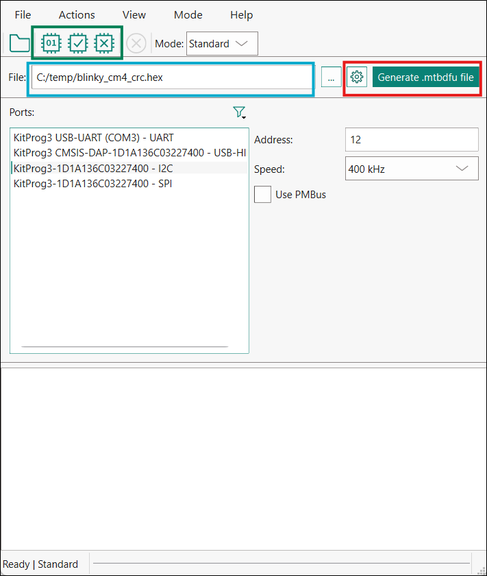
- The green box on the toolbar indicates the actions available for using a *.hex or *.bin file as an input: program, verify, and erase the device. Modify the required parameter shown in the image and select the required option.
- The blue box displays the *.hex file path selected as an input to the host tool. Only limited operations/actions are possible with selecting the *.hex or *.bin file as the input. For complex operation, use the *.mtbdfu file with the required set of commands.
- The red box indicates the Configure and Generate buttons. Click the Configure button to open the "Configuration" window (see Main window) where you can define the values of the "APPInfo" section, "timeoutMS" and "flashRowLength" of the *.mtbdfu file to be generated. The window displays the default values. They can be modified per device and use case. For more details, refer to the .mtbdfu file section. The Generate button generates the reference *.mtbdfu file for the program use case, the file will be saved in the same folder as the selected *.hex or *.bin file.
Sample JSON generated for the basic program use case
{
    "APPInfo": {
        "File Version": "0x1",
        "Packet Checkum Type": "0x0",
        "Product Id": "01020304"
    },
    "commands": [
        {
            "commandSet":[
                {
                    "cmdId":"0x37",
                    "dataLength":"0x10",
                    "repeat":"0x20"
                },
                {
                    "cmdId": "0x49",
                    "dataLength": "0x08"
                }
            ],
            "dataFile":"blinky_cm4_crc.hex",
            "flashRowLength":"0x200",
            "repeat": "EoF",
            "timeoutMS": "0x12c"
        }
    ]
}
The above JSON sample displays the template *.mtbdfu file generated from the given *.hex file as the input. The DFU Host Tool will use the *.mtbdfu file for programming the firmware *.hex file to the device.
The default flow of the DFU-MW-based firmware update includes a set of repetitive Send Data commands (0x37), a program row command (0x49) with the row checksum, and the row address to write.
The set of 0x37 commands must send exactly the same number of bytes as specified in
the flashRowLength field to provide enough data to the device DFU
buffer for the program or verify operations. The sample JSON above sends 32 (0x20)
Send Data commands and each of them passes 16 (0x10) bytes of data, so that
the amount of passed data (32*16=512) equals the length of the flash row.
You can increase the number of data bytes in order to decrease the number of operations and execution time by sending 32 bytes 16 times, 64 bytes 8 times or even sending 121 bytes 4 times and 28 bytes 1 time (121*4+28=512). These combinations depend on the interface, its maximum transfer size, bootloader, and flash row length. Some bootloaders (for example, Extended Boot) support only up to 60 bytes per packet via the SPI, and common use cases of I2C and SPI via KitProg/MiniProg usually allow the maximum of 64 bytes per packet. The maximum packet size, which can be sent out of the DFU Host Tool is 128 bytes, so the maximum data size in one packet is 121 (7 bytes describe the packet).
The JSON file uses the APPInfo
object required for the DFU communication setup. It contains potential information, the image
version, product ID of the device the same as loaded with the loader application along with
the checksum type for DFU command packet.
The sample contains the command object, which contains the list of command
sent to the device. This object can be used to send a single as well as multiple DFU commands
in the sequence required. The object contains another sub-object
commandSet, which can group multiple commands to
provide shared data across the group and repeat the set of commands.
In the JSON sample above, the command set is repeated till the end of the image file. The DFU application requires the flash row length to divide the packets into multiple sets. For more details, refer to AN 236282.
.mtbdfu file
The file contains the following sections:
APPInfo
Provides information about the device and the application:
- File Version – Indicates the application version, can be used to track updates.
- Product ID – Unique ID of the device communicating with the host.
- Packet Checksum Type – Used for the *.hex file, for DFU packet checksum.
- Timeout (ms) – Alters the timeout for the response packet (milliseconds).
- Flash Row Length – Specifies the flash row length on the device.
- Start Address – Used with a *.bin file. Defines the flash memory address where the raw binary’s first byte is written
Command
Consists of the details of the command to be sent to the device along with the data.
JSON fields available in the Command section
| Field | Description |
|---|---|
cmdId |
Command field. Specifies the DFU command number; the valid range is "0x00 - 0xFF". "0x00 - 0x49": A standard DFU command range"0x50-0xFF": Reserved for Future Use |
commandSet |
Denotes a set of commands, required for repeating a set of commands. |
dataBytes |
(Optional) The actual payload to use in a command. |
dataFile |
(Optional) Specifies the name of the input file from where the payload data will be read. |
startAddress |
Used with a *.bin file. Defines the flash memory address where the raw binary’s first byte is written. |
dataLength |
(Optional) The length of the payload data in bytes. |
flashRowLength |
Specifies the flash row length on the device. Valid only
if |
repeat |
|
startOffset |
Specifies the file offset from where data bytes will be
read. Valid only if |
sessions |
(Optional) Used to define multiple DFU sessions in the *.mtbdfu file. |
outFile |
(Optional) Specifies the file name to store intermediate packets generated by the tool. |
outCli |
(Optional) Output response data from the device to the
command line.
Note: The option does not display the
response packet metadata (status code, data length, checksum etc.),
only data payload. Use --debug, to display all DFU packets |
msg |
(Optional) Used to add comments to the *.mtbdfu file. These will not be sent to the device. |
rsp |
(Optional) A response is expected for the defined command. If no response is defined, the default expected response is 0x00 (DFU_SUCCESS). |
statusСode |
(Optional) Sets the expected status byte in the DFU response packet. If the actual status byte differs, the operation fails, the default expected status code is 0x00 (DFU_SUCCESS). |
responseLength |
(Optional) Sets the expected response data payload size (in bytes). If the actual size differs, the operation fails with the "unexpected response data" error. |
response |
(Optional) Sets the expected response data bytes. The tool compares the actual response payload byte-by-byte; a mismatch fails with the "unexpected response data" error. |
retriesCount |
Restart the connection lost for a specified number of times or until the channel gets active again. The DFU Host tool will reconnect to the device with all previous selected configuration of the channel, speed, address mode, etc.. Reconnection means establishing the channel communication again and sending the DFU start command. After successful reconnection, JSON will define the next set of tasks/commands. Equals 0 by default. |
timeoutS |
Alters the timeout for the response packet (seconds). It will apply for all retries of the operation if the "retriesCount" is non-zero. |
timeoutMS |
Alters the timeout for the response packet (milliseconds). It will apply for all retries of the operation if the "retriesCount" is non-zero. |
timeoutUS |
Alters the timeout for the response packet (microseconds). It will apply for all retries of the operation if the "retriesCount" is non-zero. |
delayS |
Sets the amount of time to wait between two commands in seconds. It is defined in a separate JSON object in the "commands" array without any additional fields in it. |
delayMS |
Sets the amount of time to wait between two commands in milliseconds. It is defined in a separate JSON object in the "commands" array without any additional fields in it. |
delayUS |
Sets the amount of time to wait between two commands in microseconds. It is defined in a separate JSON object in the "commands" array without any additional fields in it. |
Use case 1: Sample JSON generated for basic program
{
    "APPInfo": {
      "File Version": "0x1",
      "Product Id": "01020304",
      "Packet Checksum Type": "0x0"
    },
  "sessions": [
    {
      "commands": [
        {
          "dataFile":"blinky_cm4_crc.hex",
          "commandSet":[
            {
	         "cmdId":"0x37",
  	         "dataLength":"0x39",
	         "repeat":"0x8"
	       },
            {
	         "cmdId":"0x37",
	         "dataLength":"0x38"
	       },
            {
              "cmdId": "0x49",
              "dataLength": "0x08"
            }
          ],
          "repeat":"EoF",
          "flashRowLength":"0x200",
          "outFile":"log.txt"
        }
      ]
    },
    {
      "commands": [
        {
          "dataFile":"blinky_cm4_crc.hex",
          "commandSet":[
            {
	         "cmdId":"0x37",
  	         "dataLength":"0x39",
	         "repeat":"0x8"
	       },
            {
	         "cmdId":"0x37",
	         "dataLength":"0x38"
	       },
            {
              "cmdId": "0x4A",
              "dataLength": "0x08"
            }
          ],
          "repeat":"EoF",
          "flashRowLength":"0x200"
        }
      ]
    }
  ]
}
Use case 2: Sample JSON generated for multi-segment sparse binary program
{
    "APPInfo": {
        "File Version": "0x1",
        "Packet Checksum Type": "0x0",
        "Product Id": "01020304"
    },
    "commands": [
        {
            "commandSet": [
                {
                    "cmdId": "0x37",
                    "dataLength": "0x10",
                    "repeat": "0x10"
                },
                {
                    "cmdId": "0x49",
                    "dataLength": "0x08"
                }
            ],
            "dataFile": "C:/dfu-configurator/psoc4_blinky_crc.bin",
            "flashRowLength": "0x100",
            "repeat": "EoF",
            "startAddress": "0x10000",
            "timeoutMS": "0x12c"
        },
        {
            "commandSet": [
                {
                    "cmdId": "0x37",
                    "dataLength": "0x10",
                    "repeat": "0x10"
                },
                {
                    "cmdId": "0x49",
                    "dataLength": "0x08"
                }
            ],
            "dataFile": "C:/dfu-configurator/psoc4_blinky_crc2.bin",
            "flashRowLength": "0x100",
            "repeat": "EoF",
            "startAddress": "0x10100",
            "timeoutMS": "0x12c"
        }
    ]
}
Customizing the DFU Host Tool
The DFU Host tool uses a set of timeouts for read operation before disconnecting and sending a "timeout" error. These internal configurations are suited for the development and field upgrade operations for programming the firmware or communicating with the device.
However, these configurations might require modification while debugging the DFU applications with transports using the multiple breakpoint in the target side. Due to the breakpoint, the device will pause execution and might not be able to send a response desired by the DFU Host Tool. Recommended – modify the timeout configuration and rebuild the DFU Host Tool while debugging the application using the DFU transport.
Modify the source code available in sample_code. See Example code for the appropriate path for your OS.
You can go to ~/sample_code/include/backend/cychannel.h and alter variable DEFAULT_TIMEOUT_MS. By default, it is equal to 300 milliseconds. Also, you can alter the variable DEFAULT_MAX_TRANSFER_SIZE to change the maximum allowed amount of bytes to be sent in one packet (including packet header and footer) for the GUI. By default, it is equal to 128 bytes.
After making the above modification in the source code of the DFU Host tool, build the DFU Host tool again. For details of building the DFU Host tool, refer to section Example code.
Troubleshooting
| Problem | Workaround |
|---|---|
|
On common Linux distributions, the serial UART ports (usually /dev/ttySx or /dev/ttyUSBx devices) belong to the root user and to the dialout group. Standard users are not allowed to access these devices. |
An easy way to allow the current user access to the Linux machine's serial ports is by adding the user to the dialout group. This can be done using the following command:
Note:
For this command to take effect, you must log out
and then log back in. |
|
On Linux, attempts to set up or start DFU Host tool communication causes the tool to close without any messages. |
To enable DFU Host tool communication under Linux, install the udev rules for KitProg3: Disconnect the KitProg device. Execute in the terminal (root access required):
Reconnect the KitProg device. |
|
On common Linux distributions, the DFU Host tool forbids communication protocol selection after re-plugging KitProg during communication. |
Refer to the “Installation Procedure on Ubuntu Linux (x64)” section in the CYPRESS™ Programmer 2.1 CLI User Guide. |
|
KitProg3 UART is accessible but not able to read data on Linux kernel 4.15 and above or Mac OS X 10.13 and above. |
Use a third-party UART to USB bridge. Update the KitProg3 firmware to version 1.11.243 or above. |
|
After updating firmware and middleware for your application, SPI transfer speed is not as fast as expected. |
You may be able to improve performance by modifying the
src/backend/cychannelspi.cpp file. Remove the calls to
|
|
Sending command 0x47 is not supported. |
Command 0x37 can be used for transferring a large amount of data to a device due to better synchronizing with middleware. |
|
A "timeout" error occurs while running an *.mtbdfu file with the
default |
Increase the values of the timeoutMS or dataLength parameters
using the |
Version changes
This section lists and describes the changes for each version of this tool.
| Version | Change Descriptions |
|---|---|
|
1.0 |
New tool. |
|
1.1 |
Added Notice List. Added command-line interface (CLI) and handling of invalid command line arguments. Added logging for firmware update process. |
|
1.2 |
Removed Notice List. |
|
1.30 |
Updated versioning to support patches. |
|
1.40 |
Fixed minor defects. |
|
1.50 |
Added PSoC™ 4 device support. |
|
1.60 |
Updated versioning to support internal libraries update. |
|
Changed the device library file from xml to props.json. |
|
|
2.0 |
Added the .mtbdfu file format support. |
|
Added the .hex file format support. |
|
|
Added the XMC7000 device support. |
|
|
2.10 |
Added the PSOC™ Edge device support. |
|
Added new features for the .mtbdfu file support. |
|
|
Added new CLI parameters. |
|
|
2.20 |
Fixed minor bugs. |
|
Added Qt 6 support. |
|
|
2.30 |
Added USB-HID support. |
|
2.40 |
Early Access Pack |
|
2.50 |
Removed the Increased the maximum transfer size to 128 bytes per packet. Decreased delays for the SPI interface. Added CAN-FD support. Added support for PSOC™ Edge and PSOC™ Control |
|
2.51 |
Minor bug fixes. |
|
2.60 |
Minor back-end changes. |
|
2.70 |
Added the auto-repeat feature support GUI and CLI enhancement. Stability fix. |
|
2.80 |
Minor bug fixes. |
|
GUI style update. |
|
|
2.90 |
Added *.bin file format support. |
|
2.100 |
Added support for PMBus. |
|
2.110 |
Minor back-end changes.. |
|
2.120 |
Added Bridging mode support. |
|
2.130 |
GUI improvement. |
|
Minor bug fixes. |
|
|
Replaced parameters |
|
|
Added support for |
Revision history
| Revision | Date | Description |
|---|---|---|
|
** |
2018-11-09 |
New document. |
|
*A |
2019-10-16 |
Updated to version 1.1. |
|
*B |
2020-03-27 |
Updated to version 1.2. |
|
*C |
2020-09-01 |
Updated to version 1.30. |
|
*D |
2020-10-16 |
Added information about code example. |
|
*E |
2021-03-11 |
Updated to version 1.40. |
|
*F |
2022-05-10 |
Updated to version 1.50. |
|
*G |
2022-09-30 |
Updated to version 1.60. |
|
*H |
2023-05-19 |
Updated to version 2.0. |
|
*I |
2023-05-24 |
Added information to Troubleshooting section: "Sending command 0x47 to a PSoC™ 6 device via SPI is not supported". |
|
*J |
2023-11-29 |
Updated to version 2.10. |
|
*K |
2024-01-24 |
Updated to version 2.20. |
|
*L |
2024-02-07 |
Fixed broken links. |
|
*M |
2024-02-21 |
Updated to version 2.30. |
|
*N |
2024-09-27 |
Updated to version 2.50. Added troubleshooting issue for CAN-FD communication. |
|
*O |
2024-10-16 |
Updated to version 2.51. |
|
*P |
2024-12-09 |
Updated to version 2.60. |
|
*Q |
2025-03-21 |
Updated to version 2.70. |
|
*R |
2025-09-05 |
Updated to version 2.80. |
|
*S |
2025-11-14 |
Updated to version 2.90. |
|
*T |
2025-12-11 |
Updated to version 2.100. |
|
*U |
2026-02-26 |
Updated to version 2.110. |
|
*V |
2026-03-21 |
Updated to version 2.120. |
|
*W |
2026-08-28 |
Updated to version 2.130. |