Capture/Compare Unit 6 (CCU6)
The CCU6 is a high-resolution 16-bit capture and compare unit with application-specific modes, mainly for AC drive control. Special operating modes support the control of brushless DC motors using Hall sensors or Back EMF detection. Furthermore, block commutation and control mechanisms for multi-phase machines are supported. It also supports inputs to start several timers synchronously, an important feature in devices with several CCU6 kernels. The CCU6 module consists of two identical kernels CCU60 and CCU61.
Feature list
This section gives an overview over the different building blocks and their main features.
- Timer 12 block features
- Three capture/compare channels, each channel can be used either as capture or as compare channel
- Supports generation of three-phase PWM (six outputs, individual signals for high-side and low-side switches)
- 16-bit resolution, maximum count frequency = peripheral clock
- Dead-time control for each channel to avoid short-circuits in the power stage
- Concurrent update of T12 registers
- Center-aligned and edge-aligned PWM can be generated
- Single-shot mode supported
- Start can be controlled by external events
- Capability of counting external events
- Many interrupt request sources
- Hysteresis-like control mode
- Timer 13 block features
- One independent compare channel with one output
- 16-bit resolution, maximum count frequency = peripheral clock
- Concurrent update of T13 registers
- Can be synchronized to T12
- Interrupt generation at period-match and compare-match
- Single-shot mode supported
- Start can be controlled by external events
- Capability of counting external events
- Additional specific functions
- Block commutation for Brushless DC-drives implemented
- Position detection via Hall-sensor pattern
- Noise filter supported for position input signals
- Automatic rotational speed measurement and commutation control for block commutation
- Integrated error handling
- Fast emergency stop without CPU load via external signal (CTRAP)
- Control modes for multi-channel AC-drives
- Output levels can be selected and adapted to the power stage
Functional description
The CCU6 is made up of a Timer T12 block with three capture/compare channels and a Timer T13 block with one compare channel. The T12 channels can independently generate PWM signals or accept capture triggers, or they can jointly generate control signal patterns to drive AC-motors or inverters.
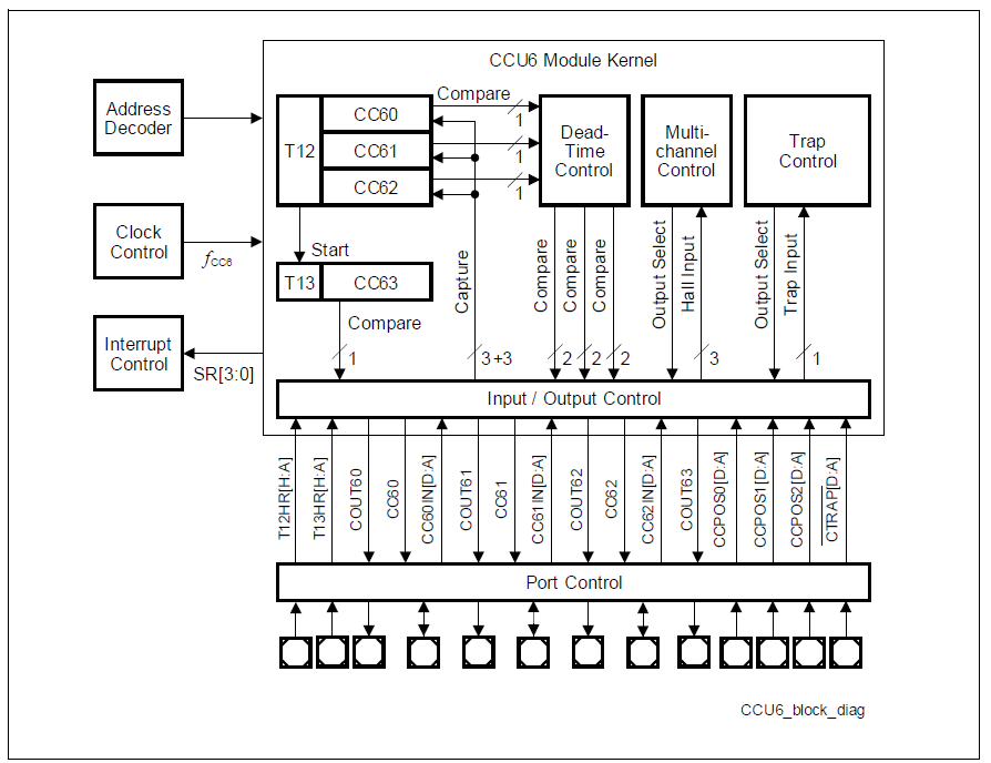
A rich set of status bits, synchronized updating of parameter values via shadow registers, and flexible generation of interrupt request signals provide means for efficient software-control. The Timer T12 can operate in capture and/or compare mode for its three channels. The modes can also be combined (For example, a channel operates in compare mode, whereas another channel operates in capture mode). The Timer T13 can operate in compare mode only. The multi-channel control unit generates output patterns which can be modulated by T12 and/or T13. The modulation sources can be selected and combined for the signal modulation.