Power Management System (PMS)
Feature list
Power Management System
- Integrated on-chip voltage regulators enabling a 5 V ± 10% or 3.3 V ± 10% single source power supply concept. External supply on all rails also supported
- Core buck regulator (EVRC) to generate VDD core supply from VDDEXTDC input supply up to 7 V to enable MOSFET supply from external pre-regulator. Synchronization support with external DCDC regulators
- Static voltage scaling support between 0.95 V – 1.025 V ± 10%, depending on product variant, in steps of 2.83 mV (using the embedded voltage regulator EVRC), depending on product variant and device type
- Primary under-voltage monitoring of supply rails including VDD, VDDEXT, (VDDEXTDC-VSSDCHS), VDDEXTDC, VDDDCLS, VDDEVRSB, VDDP3NVM, VDDM, VDDPHPHYx, VDDPHRIFx, VDDHSIF, VDDPAD, VDDCPUx, VDDPPU, VDDLMUx, VDDPHYx, and VDDRIFx, depending on product variant (not all supply rails are available on each product variant), irrespective of whether externally supplied or internally generated, to put the microcontroller into cold reset state
- Secondary independent over and under-voltage monitoring on VDDEVRSB, VDDEXT, VDDP3NVM, VDDM, VDDFLEX, VDD, VDDPMS0, VDDPMS1, VDDPMS2, VDDSBRAM, VDDPAD, VDDPHPHYx, VDDPHRIFx, VDDHSIF, VDDPHYx, VDDRIFx, VDDCPUx, VDDPPU, VDDLMUx, and VDDEXTDC supplies, depending on product variant (not all supply rails are available on each product variant). In case of violation of the thresholds, alarms are reported to the SMU (safety and security alarm management unit) and CSRM (cyber security real-time module)
- Support of multiple standby power domains PMS0, PMS1, and PMS2 supplied by separate standby supply pin (VDDEVRSB) and internal standby core regulators to meet low quiescent standby current targets. Wake-up possible from RTC, WUT, pin events, and VDDEXT supply ramp events
- 256 kB standby RAM support split across CPU0 dLMU and CPU1 dLMU and 32 kB SCR XRAM supplied in standby mode, depending on product variant
- Real Time Clock and timer support with external 32 kHz crystal with temperature trimming, depending on product variant
- Enhanced standby controller subsystem running up to maximum frequency of 100 MHz and with 32 kB XRAM, depending on product variant
Power distribution
- Support of multiple core power domains for CPU, PPU, and LMU functional blocks (depending on product variant) to reduce overall power consumption for use cases where the modules are not required
- Separate ADC power domain supplied by VDDM/VSSM supply rails to ensure minimum noise interference from the digital core and pad domains. Separate VDDM/VAREF reference supply for ADC modules
Mixed IO support
- Flexport (VDDFLEX) has separate dedicated supply pins and may be supplied with either 5 V or 3.3 V
- ADC channels supported in dedicated analog and shared digital port (P00/P33) domains
- XTAL/Oscillator/PLL supply with separate supply and ground pins for minimal noise interference
- Separate port domain for standby controller and standby functions supplied by VDDEVRSB supply rail
Separate port power domains for high speed communication interfaces
- SGMIIx and PCIe modules supplied by dedicated VDDPHPHYx and VDDPHYx supply rails
- NOR Flash interface or ethernet RGMII supplied by dedicated VDDHSIF supply rail
- Ethernet RMII/MII supplied by dedicated VDDFLEX supply rail
Functional description
The Power Management System (PMS) provides supply voltage selection, internal supply voltage generation, supply voltage monitoring, power domain and isolation control, and power management functions for the microcontroller. It also supports other microcontroller infrastructure functions through reset triggers, standby mode transitions, and real-time clock services.
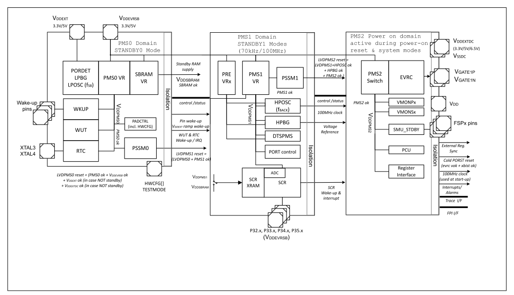
The PMS functional block constitutes the power management infrastructure, control of power related sub-functions of all modules, control of multiple power domains and voltage rails, supply generation using internal regulators, supply voltage monitors, and system power transitions.
On-chip voltage regulators are implemented in the AURIX™ TC3xx device thereby enabling a single source power supply concept. The external nominal system supply from external regulator may be either 5 V or 3.3 V. The embedded core voltage regulator (EVRC) in turn may be used to generate the VDD core supply for the core domain depending on hardware configuration pin settings. It is also possible to supply all supply pin voltages externally. All supply and generated voltages need to be available and within the operational limits to release the reset. The primary voltage monitors check for brownout conditions, setting the device into cold power-on reset state in case any voltage is below the operational limits. The power management block ensures adequate power delivery to all modules, load transient management, and interfaces to external regulators.