Flexible CRC Engine (FCE)
The FCE offers a parallel implementation of cyclic redundancy code (CRC) algorithms. The current FCE version for the AURIX™ TC3xx platform implements the IEEE 802.3 Ethernet CRC32, the AUTOSAR CRC32P4, the CCITT CRC16, and the SAE J1850 CRC8 polynomials. The primary goal of FCE is to be used as a hardware acceleration engine for software applications or operating system services that use CRC signatures. The FCE operates as a standard peripheral bus slave. It supports multiple parallel channels for CRC context. Each of these channels can be configured to use one of the CRC algorithms. In this way, several software tasks can use the same CRC algorithm at the same time.
Feature list
The FCE provides the following features:
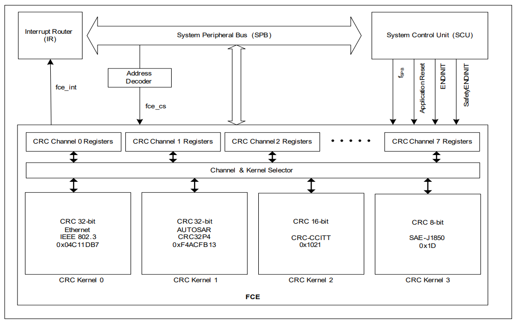
The FCE implements the following CRC polynomials:
- CRC kernel 0: IEEE 802.3 CRC32 Ethernet polynomial
- CRC kernel 1: AUTOSAR safety polynomial CRC32P4
- CRC kernel 2: CCITT CRC16 polynomial
- CRC kernel 3: SAE J1850 CRC8 polynomial
Parallel CRC implementation
- The data blocks calculated by FCE should be a multiple of the polynomial degree
- The start address of the data blocks to be computed by FCE should be aligned with the polynomial degree
Parallel channels of CRC context
- The FCE supports up to eight parallel channels of CRC context
- A channel can be configured to use any of the implemented algorithms
- Different channels can use the same or different CRC algorithms concurrently
Register interface for CRC computation:
- Input Register
- CRC Register
- Configuration registers enabling to control the CRC operation and perform automatic checksum checks at the end of a message
- Extended register interface to control reliability of FCE execution in safety applications
- FCE supports endianness conversion
- FCE can be reset independently by a software-controlled module reset. The reset affects all CRC channels
Error notification scheme via dedicated interrupt node for:
- Transient error detection: Generation of an error interrupt (maskable) with local status register (deleted by software)
- Checksum error: Generation of an error interrupt (can be masked) with a local status register (deleted by software)
- FCE provides the interrupt system with an interrupt line
Functional description
The FCE is a standard peripheral slave module that is controlled via a series of memory-mapped registers. It is fully synchronized with the peripheral bus clock and runs with a clock ratio of 1:1. An FCE kernel is the instantiation of the CRC algorithm as a parallel matrix. Each FCE kernel implements a different CRC algorithm. The FCE module contains eight channels (channel 0 - channel 7). Each channel has its own set of registers that allow the software to configure the channel, select the algorithm kernel used, write the inputs, and read the results and status of the CRC calculation. An interrupt is assigned to each channel. Using a status register assigned to each channel, the software can recognize which interrupt source is active. To support fast interrupt handling in the software, a channel status register is also provided, which basically links the status of each channel. So, the software can read this one register to get information about the pending status of each channel. Each FCE channel has the same hardware and software architecture to calculate the CRC.
A checksum algorithm based on CRC polynomial division is characterized by the following properties:
- Polynomial degree (for example, 32, which is the highest power of two of the polynomial)
- Polynomial (for example, 0x04C11DB7: The 33rd bit is omitted as it is always equal to 1)
- init value: The initial value of the CRC register
- Input data reflected: Specifies whether each byte of the parallel input data is reflected before it is used to calculate the CRC
- Result data reflected: Indicates whether the final CRC value is reflected or not
- xor value: Indicates whether a final xor operation is performed before the CRC result is returned
- BYTESWAP: If set, the order of the bytes in the input register (when using 16- or 32-bit CRC) is swapped before the CRC conversion (for endianness conversion)
As soon as a polynomial has been selected, all properties are defined. However, the FCE offers the option of controlling the two reflection steps and the final XOR operation via the CFG register. The reset values are compatible with the implemented algorithm. The final XOR control enables the selection of 0xFFFFFFFFFF or 0x00000000, which are crossed with the value POST_CRC1. These two values are used by the most common CRC polynomials.
When the software writes a value to the IR register, the CRC register is updated in the next clock cycle. The RES register is updated one cycle later after the output operations (REFOUT, XSEL). (that is, it takes two cycles from a write operation to the IR register until the result in the RES register is updated). The programmer must ensure that the CFG register is configured before the CRC calculation begins and is not changed until the final result is available.