Secure Digital Multimedia Card (SDMMC)
The purpose of the SDMMC module is to enable communication to external managed NAND flashes and SDIO (Secure digital input output) devices using the SD (Secure digital) or eMMC (embedded multimedia card) interface. The focus of the module is communication with a single eMMC memory device, SD-card, or a SDIO device.
Feature list
This section describes the features of the SDMMC module:
Communication to eMMC (embedded multimedia card) memories
Communication using 1, 4, or 8-data lines
Legacy MMC (multimedia card) and high-speed SDR (single data rate) mode supported
Communication to SD cards
Communication using 1 or 4-data lines
Default- and high speedmode supported
Communication to SDIO cards
Communication support using different levels of direct memory access (DMA) support
Programmed input output (PIO) - operation without DMA
Single operation DMA (SDMA)
Advanced DMA-2 (ADMA2)
Advanced DMA-3 (ADMA3)
Provides 1 KB SRAM for buffering up to two 512-Byte blocks
Compliant to Embedded multimedia card (eMMC) standard (5.1) with the following exceptions:
No dual voltage eMMC support, only high voltage (3.3 V)
No high clock frequencies for HS200/HS400, only 0-50 MHz
No large 4 KB sector device support, only 512-B sectors
No DDR signaling (Double data rate) only SDR signaling (Single data rate)
No data strobe support
No high-speed DDR, HS200 or HS400 speed mode support, only legacy MMC card and high-speed SDR
No "Interrupt" mode, only "device identification", "data transfer" and "inactive” mode
No clock tuning support
No multi-device support
No command queuing engine (CQE)
Compliant to SD specifications part A2 SD host controller standard specification v4.10 with the following exceptions:
No multi-slot support, only single cards
No suspend and resume functionality
No sampling clock tuning supported, only default Speed mode and high-speed mode supported
No suspend or resume operation in an SDIO card
Compliant to “SD specifications part 1 physical layer specification v4.2” with the following exceptions:
No UHS-II (Ultra high speed) voltages, only high-voltage SD memory card
No UHS-I and UHS-II speed modes, only Default Speed mode and High-Speed mode
No physical write protection switch support
No card insertion detection, only sensing of pull-up on DAT line
No SPI card support
Functional description
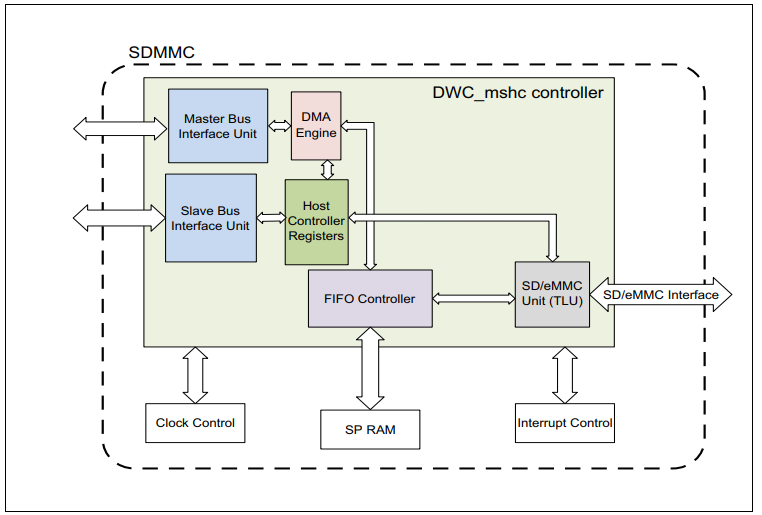
The SDMMC controller supports SD-card, eMMC, and SDIO interfaces. It contains a DMA engine for data transfer, a register unit, and a FIFO controller. The figure provides a simplified overview of SDMMC in the form of a block diagram. The SDMMC kernel is connected to the SPB slave through the FPI to AHB bridge and SRI master via AHB to SRI bridge. Access to host control registers takes place through a slave interface. Data transfers from or to external NAND memory to or from internal system memory space takes place through an internal direct memory access (DMA) engine through the master interface. The slave and master clock domains run at a frequency of fSPB. The card clock domain runs at the peripheral frequency of fSDMMC. The host controller accesses the external memory device over the GPIO pads belonging to the PORTS functional block. SDMMC has a single port RAM for packet buffering and interfacing with the FIFO controller.
Figure 1. SDMMC block diagram