System Timer (STM)
This chapter describes the System Timer (STM). The STM is designed for global system timing applications requiring both high precision and long period.
Feature list
The STM has the following features:
- Free-running 64-bit counter
- All 64 bits can be read synchronously
- Different 32-bit portions of the 64-bit counter can be read synchronously
- Flexible service request generation based on compare match with partial STM content
- Counting starts automatically after an application reset
- STM registers are reset by an Application Reset if bit ARSTDIS.STMxDIS is cleared. If bit ARSTDIS.STMxDIS is set, the STM registers are not reset by application reset, and are reset by system reset instead
Special STM register semantics provide synchronous views of the entire 64-bit counter, or 32-bit subsets at different levels of resolution.
Functional description
The STM is an upward counter, running at frequency fSTM. In case of an Application Reset, the STM is reset if bit SCU_ARSTDIS.STMxDIS is cleared. After reset, the STM is enabled and immediately starts counting up. It is not possible to affect the content of the timer during normal operation. The timer registers can only be read but not written to. The STM can be optionally disabled for power-saving purposes, or suspended for debugging purposes. In suspend mode, the STM clock is stopped but all registers are still readable.
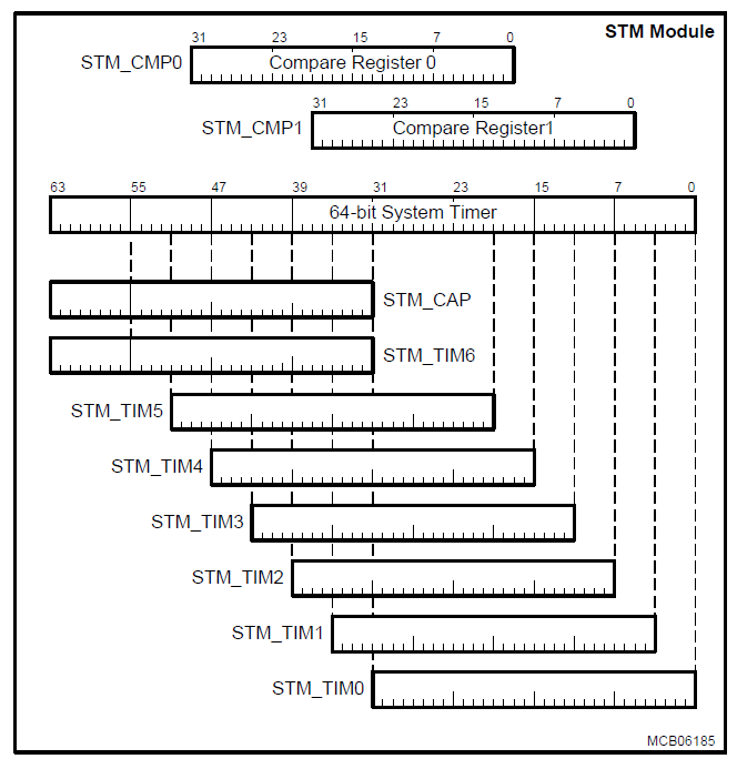
Due to the 64-bit width of the STM, it is not possible to read its entire content with one instruction. It needs to be read with two load instructions. Since the timer would continue to count between the two load operations, there is a chance that the two values read are not consistent (due to possible overflow from the low part of the timer to the high part between the two read operations). To enable a synchronous and consistent reading of the STM content, a capture register (CAP) is implemented. It latches the content of the high part of the STM each time when one of the registers TIM0 to TIM5 is read. Thus, CAP holds the upper value of the timer at exactly the same time when the lower part is read. The second read operation would then read the content of the CAP to get the complete timer value.
The STM can also be read in sections from seven registers, TIM0 through TIM6, that select increasingly higher order 32-bit ranges of the STM. These can be viewed as individual 32-bit timers, each with a different resolution and timing range.
The content of the 64-bit System Timer can be compared against the content of two compare values stored in the CMP0 and CMP1 registers. Service requests can be generated on a compare match of the STM with the CMP0 or CMP1 registers.