FlexRay Controller (ERAY)
The ERAY IP-module performs communication according to the FlexRay protocol specification v2.1, developed for automotive applications. With maximum specified clock the bit rate can be programmed to values up to 10 Mbit/s. Additional bus driver (BD) hardware is required for connection to the physical layer.
Feature List
- Conformance with the FlexRay protocol specification version 2.1
Flexible functional configuration and monitoring for software
- Configuration of message buffers with different payload lengths possible
- Up to 128 message buffers
- Each message buffer can be configured as receive buffer, as transmit buffer, or as part of the receive FIFO (first in, first out)
- Flag indicating which input buffer is currently accessible by the host
Transmit frames according to the protocol
- Data rates of up to 10 Mbit/s on each channel
- Filtering for slot counter, cycle counter, and channel
Receive frames according to the protocol
- Data rates of up to 10 Mbit/s on each channel
- Filtering for slot counter, cycle counter, and channel
Data storage of 8 Kbyte Message RAM available for message buffers and receive FIFO (first in, first out)
- Storage for example 128 message buffers with a maximum 48 byte data field or up to 30 message buffers with 254 byte data sections
- One configurable receive FIFO
- Host access to message buffers through input and output buffer
- Input buffer holds message to be transferred to the Message RAM
- Output buffer holds message read from the message RAM
- Four input buffers for building up transmission frames in parallel
- Automatically delayed read access to Input Buffer Command Request (IBCR) register if a data transfer from the input shadow buffer to the Message RAM (initiated by a previous write access to the IBCR) is ongoing
- Automatically delayed read access to Output Buffer Command Request OBCR register if a data transfer from the message RAM to the output shadow buffer (initiated by a previous write access to the OBCR) is ongoing
Flexible interrupt structure generation available
- Maskable module service requests
- Service request lines
Time management functions
- Synchronization to the cluster according to the protocol
- External clock output
- Network Management support
Functional description
The Figure 1 shows an overview of the ERAY interface.
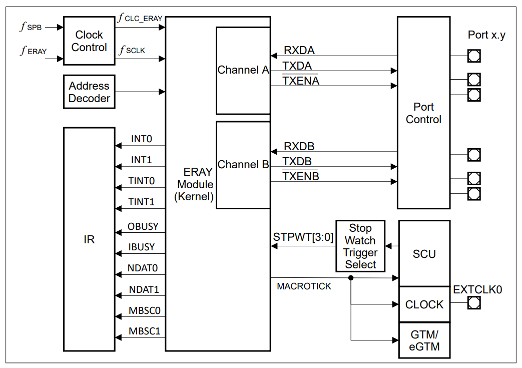
The ERAY module communicates with the external world through three I/O lines on each channel. The RXDAx and RXDBx lines are the receive data input signals, the TXDA and TXDB lines are the transmit output signals, and TXENA and TXENB are the transmit enable signals.
Clock control, address decoding, and service request control are managed outside the ERAY module kernel.
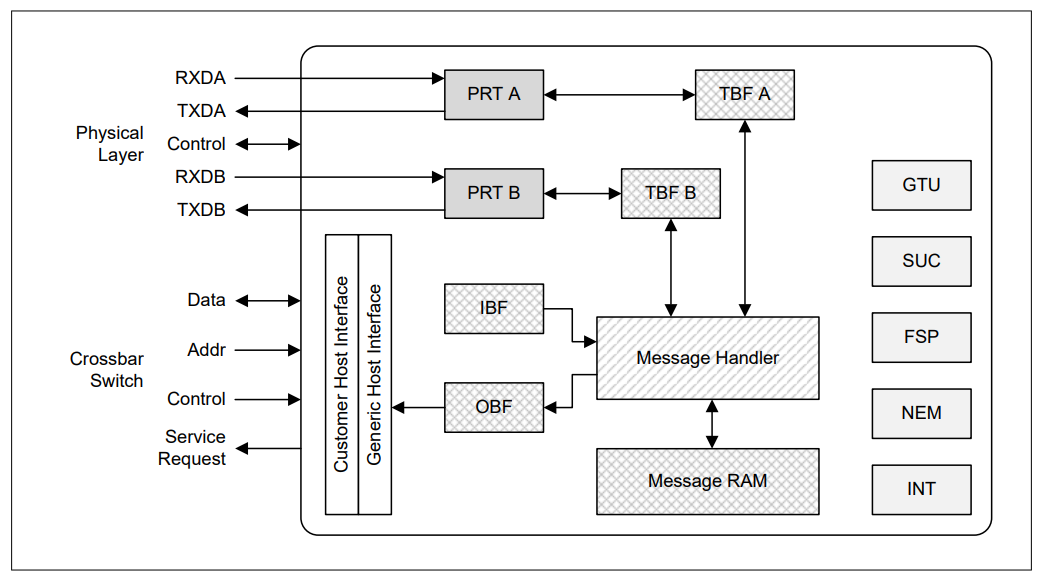
The ERAY is built up of the following main sub-modules:
Customer host interface (CIF)
Connects the FPI bus to the ERAY module through the generic host interface.
Generic Host Interface (GIF)
The ERAY module is provided with an 8/16/32-bit generic host interface prepared for the connection to a wide range of customer-specific Hosts. Configuration registers, status registers, and service request registers are attached to the respective blocks and can be accessed through the generic host interface.
Input buffer (IBF)
For write access to the message buffers configured in the message RAM, the host can write the header and data section for a specific message buffer to the input buffer. The message handler then transfers the data from the input buffer to the selected message buffer in the message RAM.
There are 4 IBFs. This enables to fill the buffer partly and at the end request transfer into message RAM. Two bits allow to switch between the two banks of IBF and one status bit signals the IBF currently active for host writes.
Output buffer (OBF)
For read access to a Message Buffer configured in the message RAM the message handler transfers the selected message buffer to the output buffer. After the transfer is completed, the host can read the header and data section of the transferred message buffer from the output buffer.
Message handler (MHD)
The ERAY Message Handler controls acceptance filtering, maintaining the transmission schedule, providing message status information and data transfers between the following components:
- Input/output buffer and message RAM
- Transient buffer RAMs of the two FlexRay protocol controllers and message RAM
Message RAM (MRAM)
The message RAM consists of a single-ported RAM that stores up to 128 FlexRay message buffers together with the related configuration data (header and data partition). For communication on a FlexRay network, individual Message Buffers with up to 254 data byte are configurable.
Transient buffer RAM (TBF 1/2)
Stores the data section of two complete messages.
FlexRay channel protocol controller (PRT A/B)
The FlexRay channel protocol controllers consist of shift register and FlexRay protocol FSM. They are connected to the transient buffer RAMs for intermediate message storage and to the physical layer through bus driver (BD).
They perform the following functionality:
- Control and check of bit timing
- Reception and transmission of FlexRay frames and symbols
- Check of header CRC
- Generation/check of frame CRC
- Interfacing to bus driver
The FlexRay channel protocol controllers have interfaces to:
- Physical layer (bus driver)
- Transient buffer RAM
- Message handler
- Global time unit
- System universal control
- Frame and symbol processing
- Network management
- Service request control
Global time unit (GTU)
The Global time unit performs the following functions:
- Generation of Microtick
Fault tolerant clock synchronization by Fault-Tolerant Midpoint (FTM) algorithm
- Rate correction
- Offset correction
- Cycle counter
- Timing control of static segment
- Timing control of dynamic segment (mini-slotting)
- Support of external clock correction
System universal control (SUC)
The System universal control controls the following functions:
- Configuration
- Wakeup
- Startup
- Normal operation
- Passive operation
- Monitor mode
Frame and symbol processing (FSP)
The frame and symbol processing controls the following functions:
- Checks the correct timing of frames and symbols
- Tests the syntactical and semantical correctness of received Frames
- Sets the slot status flags
Network management (NEM)
Handles of the network management vector
Service request control (INT)
The service request controller performs the following functions:
- Provides error and status service request flags
- Enables and disables service request sources
- Assignment of service request sources to one of the two module service request lines
- Enables and disables module service request lines
- Manages the two service request timers
- Stop watch time capturing