Inter-Integrated Circuit (I2C)
Feature list
- Compatible with I2C-bus specification version 2.1
- Master mode supported
- Multi-master mode supported
- Slave mode supported
Different speed ranges available for data transfer:
- Standard mode up to 100 kbit/s (20 kbit/s - 100 kbit/s)
- Fast mode up to 400 kbit/s (100 kbit/s - 400 kbit/s)
- High-speed mode up to 3.4 Mbit/s (500 kbit/s - 3.4 Mbit/s)
- 7-bit and 10-bit I2C-bus addressing supported
Automatic execution of low-level tasks such as:
- (De)Serialization of the bus data
- Generation or detection of start and stop signal
- Generation or detection of acknowledge signal
- Bus state detection
- Bus access arbitration in multi-master mode
- Recognition of device address in slave mode
- Configurable detection of general call address
- Configurable repeated start in master mode
Flexible clock and timing control:
- Prescaler for I2C kernel clock (from 0 to 255)
- Bit rate generation through fractional divider
- I2C-bus signal timing adjustment
FIFO for buffering data from or to CPU with following features:
- 8 FIFO stages based on 32-bit width
- Configurable data alignment (byte, half word, word)
- Configurable sizes for burst, transmit and receive package
- FIFO usable as flow controller (seamless DMA flow)
Advanced interrupt handling:
- 4 data transfer interrupt requests (burst, last burst, single, last single) resulting in one single data transfer interrupt
- Protocol interrupt with 7 sources (address match, general call, master code, arbitration lost, not-acknowledge received, transmission end, receive mode)
- Error interrupt with 4 sources (overflow or underflow of FIFO for transmit or receive)
Pretended Networking:
- High-speed mode, fast mode and standard mode work with the system clock frequency fI2C. that can reach a minimum of 5 MHz
Functional description
The I2C module is a functional block that offers communication functionality according to the I2C-bus specification version 2.1. I2C is either connected to the SPB bus or the COMPB bus with a slave interface including a set of special function registers (SFRs). The bus interface used by the I2C module is defined in the device specific chapter.
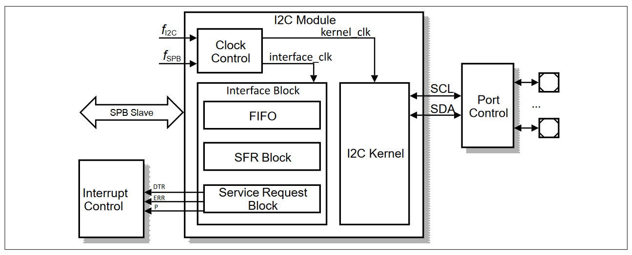
The I2C module communicates with the external world through a pair of I/O lines. A serial data line (SDA) and a serial clock line (SCL) carry the information between the devices. The SDA and SCL are connected to a positive supply voltage through pull-up resistors. In quiescent state, when the bus is free, both lines are high. During communication the lines are alternatively pulled to low. The output stages of devices connected to the bus must have an open-drain (CMOS) or open-collector (bipolar) to perform a wired-AND function.
The I2C protocol was developed to provide a simple and efficient data transfer between multiple devices over a short distance. It uses a bidirectional serial bus with two wires. The device can work as master or as slave. The master initiates the transfer, generates the clock pulses, and terminates the transfer; it addresses a slave through a 7-bit or 10-bit address. Data can flow in either direction. In many applications there is only one master, typically a single-chip microcontroller, which communicates with several slaves, for example general purpose peripherals or application specific circuits. However multi-master systems with arbitration and collision detection are also possible.
Data on the I2C-bus can be transferred at rates of up to 100 kbit/s in standard mode, up to 400 kbit/s in fast mode, and up to 3.4 Mbit/s in high-speed mode. A slow slave may stretch the clock period. The number of devices connected to the same I2C-bus is limited by a maximum bus capacitance of 400 pF.
The module relieves the CPU from many time-critical tasks. The clock for the kernel of the I2C module is derived from the system clock through a pre-scaler. An additional fractional divider generates the desired bit rate. The exact timing of the I2C-bus signals can be adjusted.
A FIFO is used for data transfer between the CPU and the I2C module during transmission and reception. This allows writing and reading of multiple bytes. Data alignment and data sizes can be configured. Six separate interrupt requests are available: for filling or emptying the FIFO, for reacting on certain protocol events, and for handling errors.