General Purpose Timer Unit (GPT12)
The General Purpose Timer Unit blocks GPT1 and GPT2 have very flexible multifunctional timer structures which may be used for timing, event counting, pulse width measurement, pulse generation, frequency multiplication, and other purposes.
They incorporate five 16-bit timers that are grouped into the two timer blocks GPT1 and GPT2. Each timer in each block may operate independently in a number of different modes such as Gated Timer or Counter Mode, or may be concatenated with another timer of the same block.
Each block has alternate input/output functions and specific interrupts (service requests) associated with it. Input signals can be selected from several sources by register PISEL. The GPT12 module is clocked with clock fGPT.
Feature list
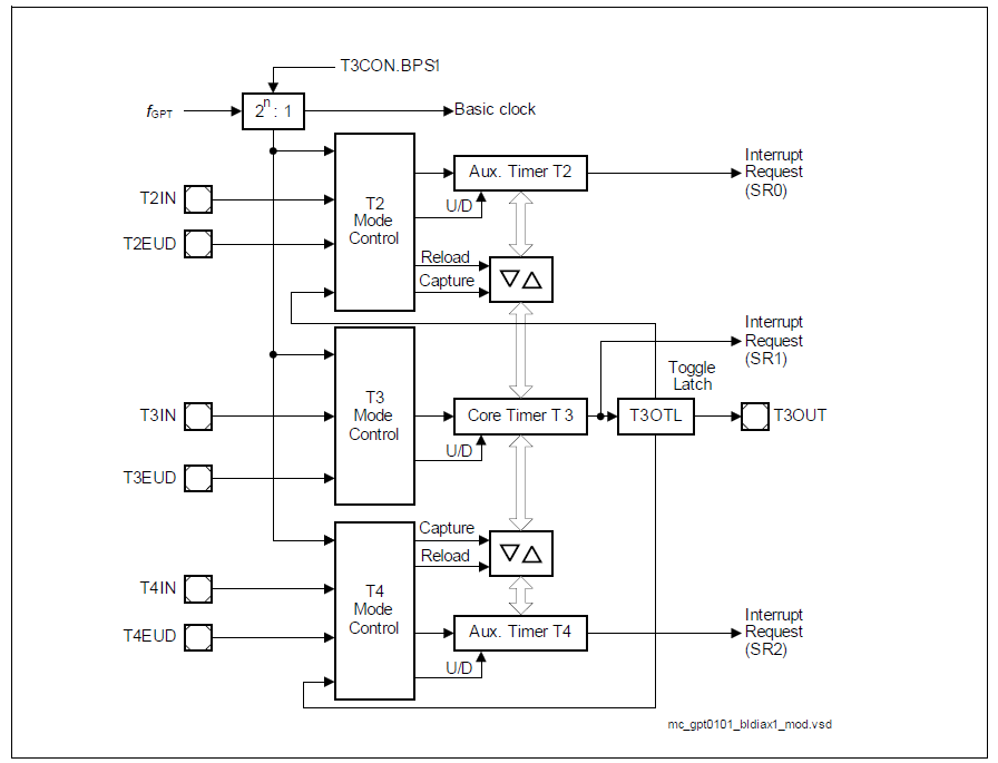
Timer Block GPT1 contains three timers/counters: The core timer T3 and the two auxiliary timers T2 and T4. The maximum resolution is fGPT/4. The auxiliary timers of GPT1 may optionally be configured as reload or capture registers for the core timer.
The following list summarizes the supported features:
- fGPT/4 maximum resolution
- 3 independent timers/counters
- Timers/counters can be concatenated
4 operating modes:
- Timer mode
- Gated Timer mode
- Counter mode
- Incremental Interface mode
- Reload and Capture functionality
- Separate interrupts
Timer Block GPT2 contains two timers/counters: The core timer T6 and the auxiliary timer T5. The maximum resolution is fGPT/2. An additional Capture/Reload register (CAPREL) supports capture and reload operation with extended functionality
The following list summarizes the supported features:
- fGPT/2 maximum resolution
- Two independent timers/counters
- Timers/counters can be concatenated
Three operating modes:
- Timer mode
- Gated Timer mode
- Counter mode
- Extended capture/reload functions via 16-bit capture/reload register CAPREL
- Separate interrupts
Functional description
Timer block GPT1
All three timers of block GPT1 (T2, T3, T4) can run in one of 4 basic modes: Timer Mode, Gated Timer Mode, Counter Mode, or Incremental Interface Mode. All timers can count up or down. Each timer of GPT1 is controlled by a separate control register TxCON.
Each timer has an input pin TxIN (alternate pin function) associated with it, which serves as the gate control in Gated Timer Mode, or as the count input in Counter Mode. The count direction (up/down) may be programmed via software or may be dynamically altered by a signal at the External Up/Down control input TxEUD (alternate pin function). An overflow/underflow of core timer T3 is indicated by the Output Toggle Latch T3OTL, whose state may be output on the associated pin T3OUT (alternate pin function). The auxiliary timers T2 and T4 may additionally be concatenated with the core timer T3 (through T3OTL) or may be used as capture or reload registers for the core timer T3.
The current contents of each timer can be read or modified by the CPU by accessing the corresponding timer count registers T2, T3, or T4. When any of the timer registers is written to by the CPU in the state immediately preceding a timer increment, decrement, reload, or capture operation, the CPU write operation has priority in order to guarantee correct results.
The interrupt requests of GPT1 are signalled on service request lines SR0, SR1, and SR2.
The input and output lines of GPT1 are connected to pins. The control registers for the port functions are located in the respective port modules.
GPT1 core timer T3 control
The current contents of the core timer T3 are reflected by its count register T3. This register can also be written to by the CPU, for example, to set the initial start value. The core timer T3 is configured and controlled via its control register T3CON.
Timer T3 Run control
The core timer T3 can be started or stopped by software through bit T3R (Timer T3 Run Bit). This bit is relevant in all operating modes of T3. Setting bit T3R will start the timer, clearing bit T3R stops the timer. In Gated Timer mode, the timer will only run if T3R = 1 and the gate is active (high or low, as programmed).
Count direction control
The count direction of the GPT1 timers (core timer and auxiliary timers) can be controlled either by software or by the external input pin TxEUD (Timer Tx External Up/Down Control Input). These options are selected by bits TxUD and TxUDE in the respective control register TxCON. When the up/down control is provided by software (bit TxUDE = 0), the count direction can be altered by setting or clearing bit TxUD. When bit TxUDE = 1, pin TxEUD is selected to be the controlling source of the count direction. However, bit TxUD can still be used to reverse the actual count direction. The count direction can be changed regardless of whether or not the timer is running.