Micro Second Channel (MSC)
Feature list
Flexible functional configuration for software
- Baud rate configuration
Transmit MSC frames to external devices and handle all protocol relevant topics
- Supports 64-bit data frames and 32-bit data frames transmission
- Asynchronous baud rate adjustment block
- Supports command frame transmission through slow channel
- Selectable MSC Manchester code transmission: combination of downstream data, clock and enable signals transmitted in the same line
Receive MSC frames from external devices and handle all protocol relevant topics
- Programmable upstream data frame length (16 or 12 bits)
- Programmable delay of the receive interrupt after the last stop bit (0 or 1-bit time)
- Flexible interrupt structure generation available
- Selectable pin types of downstream channel interface: four low-voltage differential signaling (LVDS) output drivers or four digital general purpose input output (GPIO) pins
- Additional clock input selection is available, fSRI = 500 MHz. This clock selection with an additional clock divider offers the possibility to provide a MSC baud rate configuration up to 50 MHz without Asynchronous Baud Rate Adjustment (ABRA) usage
Functional description
The MSC is a serial interface that is especially designed to connect external power switch devices. The serial data transmission capability minimizes the number of pins required to connect such external power switch devices. Parallel data information (coming from the timer units) or command information is sent out to the power switch device using a high-speed synchronous serial data stream (downstream channel). The MSC receives data and status back from the power switch device through a low-speed asynchronous serial data stream (upstream channel).
Parallel requests from on chip bus masters to a module will be executed sequentially through the on-chip bus system. A read-modify-write feature provides an atomic read/write sequence where no other master can access the module in between. Module hardware semaphores are not supported.
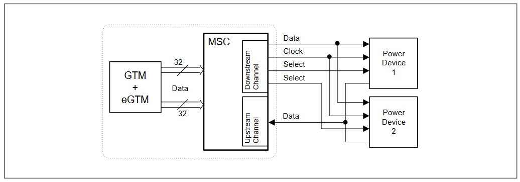
The following figure shows a typical application in which an MSC interface controls two power switch devices. Output data is provided by the module.
Some MSC applications are:
- Control of the external power switching unit through the downstream channel
- Receiving information back from power switching unit
- Serial connections to other peripheral devices
The MSC interface provides a serial communication link typically used to connect power switches or other peripheral devices. The serial communication link includes a fast synchronous downstream channel and a slow asynchronous upstream channel.
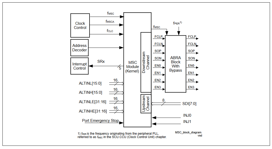
Figure 1 shows a global view of the MSC interface signals.
The downstream and upstream channels of the MSC module communicate with the external world through nine I/O lines. Eight output lines are required for the serial communication of the downstream channel (clock, data and enable signals). One out of the eight input lines is used as serial data input signal for the upstream channel. The source of the serial data to be transmitted by the downstream channel can be MSC register contents or data that is provided at the ALTINL/ALTINH input lines. These input lines are typically connected to other on-chip peripheral units (for example with a timer unit like the GTM). A Port Emergency Stop input signal makes it possible to set bits of the serial data stream to dedicated values in case of emergency. Clock control, address decoding and interrupt service request control are managed outside the MSC module kernel. Service request outputs are able to trigger an interrupt or a DMA request.