Gigabit Ethernet (GETH)
This chapter describes the Ethernet MAC.
The Ethernet Quality of Service Controller IP was designed to support real-time networking. In IEEE 802 LAN standards, the media access control (MAC) is the layer that controls the hardware responsible for interaction with the transmission medium.
Feature lists
The DesignWare Controller (DWC) ensures the Ethernet Quality of Service (ether_qos). Abbreviated in total as „DWC_ether_qos“ the controller enables a host to transmit and receive data over Ethernet in compliance with the IEEE 802.3-2008 standard. In addition to the default interfaces defined in the IEEE 802.3 specifications, the DWC_ether_qos supports several industry standard interfaces to the PHY.
The controller is compliant with the following standards:
IEEE 802.3-2008 for Ethernet MAC, Media Independent Interface (MII)
IEEE 1588-2008 for precision networked clock synchronization
IEEE 802.1AS-2011 and 802.1-Qav-2009 for Audio Video (AV) traffic
IEEE 802.3az-2010 for Energy Efficient Ethernet (EEE)
AMBA 2.0 for AHB master, AHB slave, and APB slave ports
RGMII/RTBI specification version 2.6 from HP/Marvell
RMII specification version 1.2 from RMII consortium
MAC Tx and Rx common features
The DWC_ether_qos controller supports the following features common to both MAC Tx and Rx:
Separate transmission, reception, and control interfaces to the application
Configurable big-endian and little-endian mode for Transmit and Receive paths
10, 100, and 1000 Mbps data transfer rates with the following PHY interfaces:
IEEE 802.3-compliant interface to communicate with an external Gigabit or Fast Ethernet PHY
RGMII interface (optional) to communicate with an external gigabit PHY
RMII interface (optional) to communicate with an external Fast Ethernet PHY
Half-duplex operation:
CSMA/CD Protocol support
Flow control using backpressure support (based on implementation-specific white papers and UNH Ethernet Clause 4 MAC Test Suite - Annex D)
Packet bursting and packet extension in 1000 Mbps half-duplex operation
Standard IEEE 802.3az-2010 for Energy Efficient Ethernet in (G)MII and Reduced Gigabit Media Independent Interface (RGMII) PHYs
64-bit data transfer interface on the application side
Network statistics with RMON or MIB Counters (RFC2819/RFC2665)
Module to support Ethernet packet timestamping as described in IEEE 1588-2002 and IEEE 1588-2008 (64-bit timestamps given in the Tx or Rx status of PTP packet). Both one-step and two-step timestamping is supported in TX direction
Flexibility to control the Pulse-Per-Second (PPS) output signal (ptp_pps_o)
Optional MDIO (Clause 22 and Clause 45) master interface for PHY device configuration and management
Programmable control to clear interrupt status bits on writing 1 to it
Programmable control to provide Slave error response for accesses to the reserved registers within the CSR address space
MAC Tx features
The DWC_ether_qos controller supports a number of MAC Tx features.
The DWC_ether_qos supports the following MAC Tx features:
Preamble and start of packet data (SFD) insertion
Separate 32-bit status for each packet transmitted from the application
Automatic CRC and pad generation controllable on a per-packet basis
Programmable packet length to support Standard or Jumbo Ethernet packets with up to 9 KB of size
Programmable Inter Packet Gap (40–96 bit times in steps of 8)
IEEE 802.3x Flow Control automatic transmission of zero-quanta Pause packet when flow control input transitions from assertion to de-assertion (in full-duplex mode)
Option to transmit packets with reduced preamble size in full-duplex mode
Insert, replace, or delete queue/channel-based VLAN tags
MAC Rx features
TThe DWC_ether_qos controller supports the following MAC Rx features:
Automatic Pad and CRC Stripping options
Option to disable Automatic CRC checking
Preamble and SFD deletion
Separate 112-bit or 128-bit status
Programmable watchdog timeout limit
Flexible address filtering modes:
Up to 31 additional 48-bit perfect (DA) address filters with masks for each byte
Up to 31 48-bit SA address comparison check with masks for each byte
Option to pass all multi-cast addressed packets
Promiscuous mode to pass all packets without any filtering for network monitoring
Pass all incoming packets (as per filter) with a status report
Additional packet filtering:
VLAN tag-based: Perfect match and Hash-based (optional) filtering. Filtering based on either outer or inner VLAN tag is possible
Extended VLAN tag based filtering 8 filter selection
IEEE 802.1Q VLAN tag detection and option to delete the VLAN tags in received packets
Optional module to detect remote wake-up packets and AMD magic packets
Optional forwarding of received Pause packets to the application (in full-duplex mode)
Optional Receive module for Layer 3/Layer 4 checksum offload for received packets
Optional stripping of up to two VLAN Tags and providing the tags in the status
Transaction Layer (MTL) features
The DWC_ether_qos supports a number of Tx and Rx Transaction Layer (MTL) features. The MTL block consists of the following FIFOs: Tx FIFO and Rx FIFO. The FIFO size is 4kB for Tx and 8 kB for Rx. The FIFO space is shared by multiple queues (up to 4 Tx and up to 4 Rx queues). You can configure the buffer size for each queue in multiples of 256 bytes.
The MTL includes the following feature groups:
MTL Tx and Rx common features
MTL Tx features
MTL Rx features
DMA block features:
The DWC_ether_qos controller supports a variety of DMA block features. The DMA block exchanges data between the MTL block and system memory. The well defined descriptors structure acts as a software and hardware interface. The application can use a set of registers (DMA CSR) to control the DMA operations.
The DMA block supports the following features:
32-bit data transfers
Multi-channel Transmit and Receive engines (up to 4 Transmit channels; up to 4 Receive channels)
Separate DMA channel in the Transmit path for each queue in MTL
Single or multiple DMA channels for any number of queues in MTL Receive path
Optimization for packet-oriented DMA transfers with packet delimiters
Byte-aligned addressing for data buffer support
Dual-buffer (ring) descriptor support
Descriptor architecture to allow large blocks of data transfer with minimum CPU intervention (each descriptor can transfer up to 32 KB of data)
Comprehensive status reporting for normal operation and transfers with errors
Individual programmable burst length for Tx DMA and Rx DMA engines for optimal host bus utilization
Programmable interrupt options for different operational conditions
Per-packet Transmit or Receive Complete Interrupt control
Round-robin or fixed-priority arbitration between the Receive and Transmit engines
Start and Stop modes
Separate ports for host CSR access and host data interface
Routing of received packets to the DMA channels based on the DA or VLAN Priority in multi-channel DMA configurations
Option to split the packet header (Layer 3 and Layer 4) and payload in different buffers
Time-sensitive conditional packet transmission by comparing the Slot Time information provided in the descriptor (useful for AV applications)
Programmable control for Transmit Descriptor posted writes to improve the throughput
Functional description
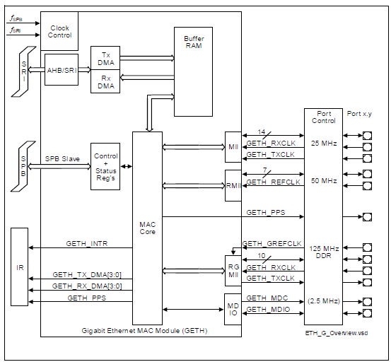
The DesignWare Controller (DWC) ensures the Ethernet Quality of Service (ether_qos). Abbreviated in total as „DWC_ether_qos“ the controller enables a host to transmit and receive data over Ethernet in compliance with the IEEE 802.3-2008 standard. As shown in figure“Ethernet MACblock diagram“, one AHB or AXI Master interface is connected to all DMA channels. The DMA arbiter helps in arbitration of paths (Transmit and Receive) in all channels. Each channel has a separate set of Control and Status registers (CSR) for managing the Transmit and Receive functions, descriptor handling, and interrupt handling.
The following figure shows the basic structure of the Ethernet MAC module.
Figure n1. Ethernet MAC block diagram
The DWC_ether_qos supports several options to interface the application: to the MAC through native CORE, MTL, or DMA interfaces; or through AHB or AXI interfaces. It also supports a variety of PHY interfaces as well.
AHB Interface
The AHB interface is designed to integrate with AMBA High-Performance Bus (AHB) on the application side. The AHB interface transfers the data to and from system memory through the AHB master interface. When the AHB interface is selected, the host CPU uses the default 32-bit AHB slave interface to access the Control and Status registers (CSRs) of the DWC_ether_qos subsystem.
PHY Interface
The DWC_ether_qos supports any one or a combination of the following PHY interfaces:
Media Independent Interface (MII)
Reduced Gigabit Media Independent Interface (RGMII)
Reduced Media Independent Interface (RMII)
Audio and Video features
DWC_ether_qos can be used in Audio Video (AV) mode, and the supported features are compliant to the industry standards for AV traffic.
DWC_ether_qos supports the following Audio Video (AV) features:
Separate channels or queues for AV data transfer in 100 Mbps and 1000 Mbps modes
IEEE 802.1-Qav specified credit-based shaper (CBS) algorithm for Transmit channels
Single Tx FIFO and Rx FIFO (MTL) for all selected queues (system-side interface [AHB] remains the same)
Programmable Slot Interval with range from 1μ to 4096μs and granularity of 1μs
Generic Queuing Support
Programmable control for routing Receive packets with Multicast/Broadcast destination address to a programmable Receive Queue. Support routing of Untagged Receive packets to a programmable Receive Queue. Programmable control for routing VLAN tagged and untagged IEEE 1588 PTP over Ethernet Receive packets to a same or separate programmable Receive Queue. Programmable control for routing Unicast/Multicast Receive packets that fail the destination address filter to separate programmable Receive Queues.
Monitor, Testing, and Debugging features
The monitoring, testing, and debugging mechanisms in DWC_ether_qos help in effective analysis of the configured features.
DWC_ether_qos supports the following features for monitoring, testing, and debugging:
Internal loopback from Tx to Rx on the GMII or MII for debugging
DMA states (Tx and Rx) as status bits
Debug status register that gives status of FSMs in Transmit and Receive data paths and FIFO fill-levels
Application Abort status bits
MMC (RMON) module
Current Tx or Rx Buffer pointer as status registers
Current Tx or Rx Descriptor pointer as status registers
Statistical counters to calculate the bandwidth served by each Transmit channel when AV or DCB support is enabled
Tx or Rx Queues memory accessible through Slave port for debug