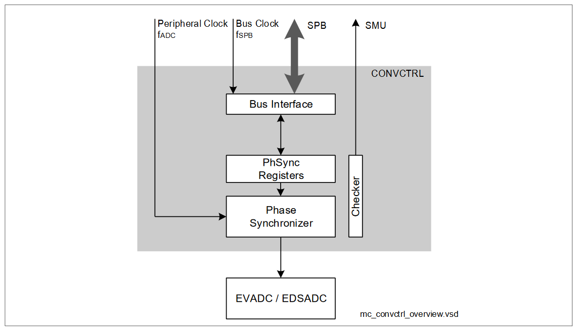
Converter Control Block (CONVCTRL)
The converter control block summarizes control functions which are common for all converters implemented in the product. The Phase Synchronizer (PhSync) function provides a clock enable signal to synchronize the clock signals of all analog blocks. Furthermore, the converter control block contains the registers which are required to configure the associated functions.
The phase synchronizer provides a specific clock enable signal to synchronize the operation of all analog blocks within modules EVADC and EDSADC. These analog blocks use the voltage references (VAREF and VAGND) and synchronizing their clock edges avoids performance losses caused by mutual cross-coupling via the reference lines. The CONVCTRL ensures that all switching activities within the connected analog blocks occur at the same clock edge of fPER so the ringing that occurs on the reference lines does not disturb the operation of another analog block.
Feature list
The following features describe the functionality of the PhSync:
Synchronization of all analog blocks
- Centrally generated clock enable signal
- Local synchronization stages within each module
- Target frequency selectable to adapt to system requirements
- Based on the peripheral clock signal fPER (160 MHz)
Functional description
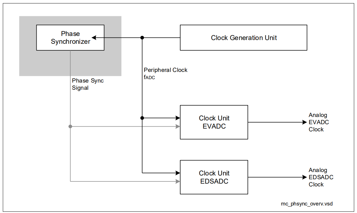
The Phase Synchronizer module (PhSync) provides a centralized clock enable signal for all analog blocks (EVADC, EDSADC). This synchronization ensures that the analog blocks do not disturb each other by drawing current peaks from the reference voltage lines at adjacent edges of the basic peripheral clock fPER. The frequency of the resulting analog clock enable signal is configurable within a certain range. The PhSync broadcasts its clock enable signal, while each connected module locally generates its own analog clock signal based on the PhSync signal. With this approach no additional clock balancing is required. The basic module clock is the peripheral clock signal fPER.
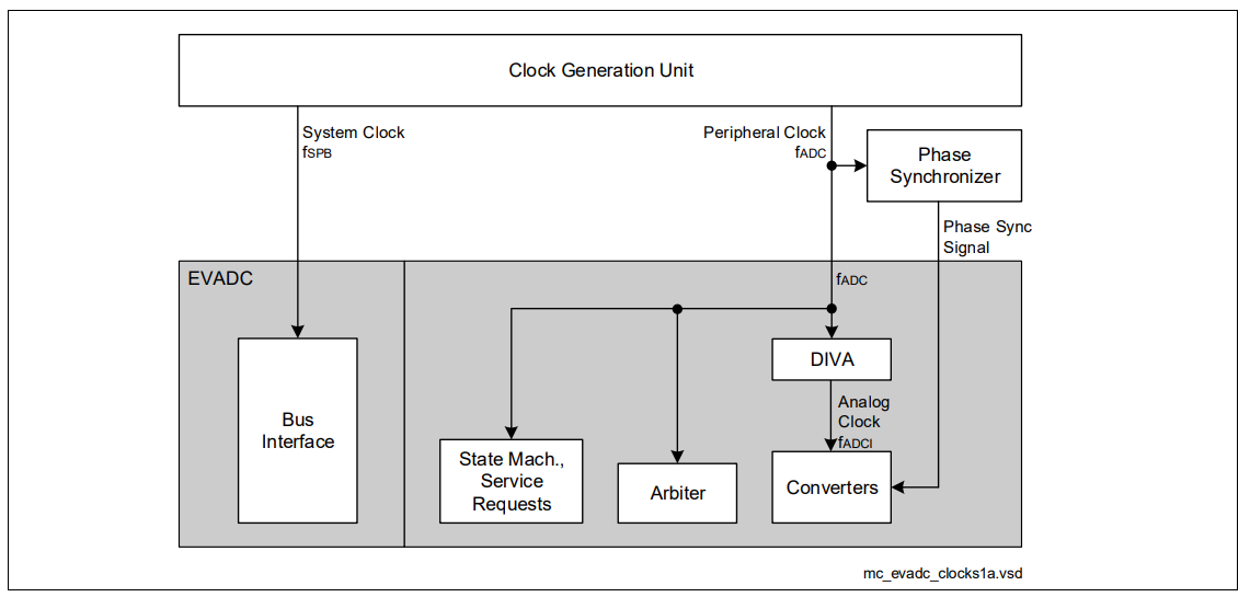
The figures below show the analog clock generation mechanisms used in the connected modules.
The Phase Synchronizer counts peripheral clock (fPER) cycles and generates a clock enable signal after a configurable number of clock cycles. The prescaling factor can be selected from 2 to 16, which equals an analog clock frequency of 80 MHz to 10 MHz (assuming fPER = 160 MHz). The phase synchronization signal triggers all local clock generation blocks to generate a clock edge with a subsequent1) rising edge of the common peripheral clock.
Generation of the analog clock signal
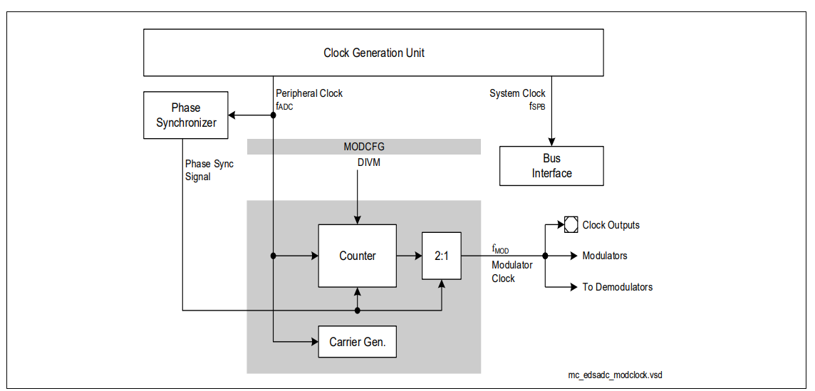
The local clock generation units generate the respective analog clock signal triggered by the phase synchronization signal. The corresponding analog clock edge or trigger signal is generated upon a subsequent rising edge of the reference clock fPER. The EVADC evaluates the level of the phase synchronizer signal to start a conversion. The EDSADC evaluates the rising edge of the phase synchronizer signal to generate clock pulses. Each unit can configure a certain phase shift for the synchronized analog clock or trigger. This way, all analog modules can switch on exactly the same clock edge, or they can switch in a certain sequence that can be configured by the user.
Application considerations
The operation of the CONVCTRL and, hence, its behavior is programmable. This makes it suitable for different applications while requiring a minimum of handling.
Clock synchronization
To eliminate the interference of concurrently operating ADC channels, the converters can operate in a synchronized way so each of them can reach its optimum performance. The Phase Synchronizer distributes a clock control signal which is used by the converters to generate a local clock signal. After reset, the clock synchronization is active within the converters. The Phase Synchronizer, therefore, must be configured to generate the clock synchronization signal. This synchronization signal is used within the EDSADC and the EVADC.
The EDSADC uses the synchronization signal directly to generate its modulator clock. Therefore, the phase synchronizer must be programmed according to the required EDSADC modulator frequency, i.e. fPHSYNC = fMOD. The EVADC uses the synchronization signal to start a conversion. Therefore, the analog clock of the EDVADC fADCI must be selected as an integer multiple of the phase synchronizer frequency, i.e. fADCI = fPHSYNC or fADCI = fPHSYNC × 2.