Single Edge Nibble Transmission (SENT)
Feature list
- Conformance with SENT specification J2716 201604
- Flexible functional configuration for software
Baud rate generation: Data rates of up to 65.8 kbit/s at 3 μs tick length and 6 data nibbles on each channel
- Support of standard tick times (3 μs through 90 μs)
- Message tick time programmable between 0.2 μs and 1024 μs
- Configurable frame length (default is 24-bit) and maximum data size of 32 bits
- Digital Glitch filter suppressing noise
- Optional output inversion for use of external open drain transistor
- Optional input inversion for use of external open transistor for level shifting
Receive SENT frames from external devices and handle all protocol relevant topics
- LMU channels per instance implemented, all working independently in parallel
- Programmable nibble sorting to relieve CPU
- Transparent mode (nibble CRCs are written to the receive control register for software processing)
- Status nibble optionally included in the checksum
- Optional serial data processing
- Option to enable or disable the check of the next calibration pulse before validation of received data
- Support frequency drift analysis based on frame length for frames with pause pulse
- Indication of system status: STOP, INITIALIZED, RUNNING, SYNCHRONIZED
- Time stamp generation
- Watchdog on incoming frames
- Support of trailing pause nibble of any length (even longer than 70 ticks)
- Support of SPC (Short PWM Code)
Flexible interrupt structure generation available
The receiver module will monitor the message for the following error conditions:
- Calibration pulse length deviates more than +/-25% from the nominal 56 ticks
- Too many or too few nibbles between calibration pulses
- Checksum error
- Successive calibration pulse differ by more than 1.5625%
- Any nibble data values measured as < 0 or > 15
- Sticky interrupt flags, error interrupt optional
- Interrupt on status nibble violation
- Buffer overrun detection
Functional description
The LMU module communicates with the external world through one I/O line for each channel. The SENT input lines are the receive data input signals. They can overlay ADC inputs. If the optional SPC mode is used, they can be used on a port configured with an open drain transistor. In this way the optional SPC data can be transmitted and the line is used bi-directionally. For an external transceiver, the receive and transmit path can be routed to two different ports.
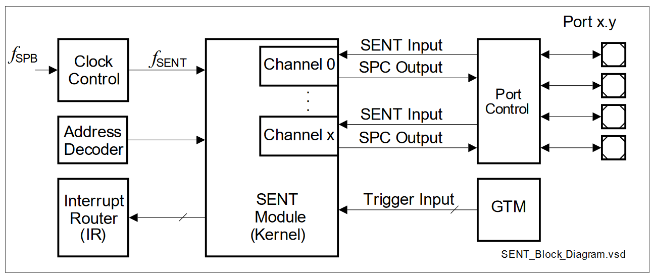
The SENT interface provides a serial communication link typically used to connect sensors or other peripheral devices. Clock control, address decoding, and service request control are managed by the LMU module kernel. The SENT IP-module performs communication according to the SENT specification SAE J2716 042016. While staying compliant to this standard, it is able to cover as well the Short PWM Code (SPC) protocol extensions. This enhances the standardized SENT protocol defined by SAE J2716 042016. SPC enables the use of enhanced protocol functionality like “synchronous”, “range selection” and “ID selection” protocol mode.
Receive data on a SENT channel can be set up according to the underlying application. In particular the number of nibbles forming one value is configurable. The message storage consists of two 32-bit registers for each channel, representing a flexible double buffer system. In SPC mode, maintaining the sample and transmission schedule as well as providing message status information is supported. The register set of the SENT module can be accessed directly by the CPU for configuration, data read out and status query.