Direct Memory Access (DMA)
The DMA component allows data to be transferred between memory and peripherals (or between memory locations) without involving the CPU. This improves performance by freeing up the CPU to handle other tasks while the transfer occurs in the background. DMA is commonly used for high-speed data operations, communication, and data streaming.
Feature list
The DMA is a fast and flexible DMA controller that has the following features:
Resource Partitions
An application running one set of defined move data functions shall be free from interference by another application running another set of defined move data functions
Each RP has independent Access Enable control via enabling individual Master TAG identifiers to have write access enable to the RP and assigned DMA channels
Each RP has a unique master tag identifier driven onto the on-chip bus during a DMA move
Each RP executes on-chip bus accesses in supervisor or user mode
DMA channels
The DMA supports multiple independent DMA channels
Each DMA channel shall be assigned to a RP
Each DMA channel shall be individually programmable
Each DMA channel TCS shall be stored in DMARAM
The DMA channel source and destination address pointers shall be 32-bit wide address counters
Wrap buffer addressing mode with flexible circular buffer sizes
The DMA channel source and destination wrap buffers shall be selectable
Programmable data width of DMA moves
Double Buffering Operations
The DMA transaction can execute read or fill DMA transfers from one of two source or destination buffers
A control bit allows the re-direction of DMA transfers from the one buffer to the other buffer
DMA Linked List (DMALL)
The current DMA transaction can load the next DMA channel TCS into the DMARAM by overwriting the existing DMA channel TCS
The next DMA transaction may be auto started
DMA Channel Request Control
DMA Software Request
DMA Hardware Request
DMA Daisy Chain Request
DMA Auto Start Request
Move Engine
Any ME shall service a DMA request from any DMA channel
DMA requests from the highest number DMA channel are serviced first by a ME
Multiple MEs support the parallel servicing of DMA requests
SRI-source to SRI-destination data block move throughput <8 Mbyte DMA moves per DMA transaction
SPB-source to SPB-destination data block move throughput <1 Mbyte DMA moves per DMA transaction
DMA On-Chip Bus Switch
DMA read moves and DMA write moves are directed by the DMA on chip bus switch to different sources and destinations depending on the source or destination address
Buffer capability for move actions on the buses (at least 1 x DMA move per bus is buffered)
Interrupt Triggers
Each DMA channel generates one interrupt trigger with an unique interrupt vector and priority level
Each DMA RP generates one error interrupt trigger with an unique interrupt vector and priority level
Operating frequencies
The DMA configuration and request control function works at the SPB clock frequency
The ME function works at the SRI clock frequency in order to maximise the data throughput for DMA moves from SRI source addresses to SRI destination addresses
Functional description
The DMA moves data from source locations to destination locations without the intervention of the CPU or other on chip devices. A data move is controlled by the transaction control set of an active DMA channel and is executed by a move engine. The transaction control sets are loaded into the DMARAM either directly through software writes through the configuration interface, or indirectly through linked list operations. A DMA channel is activated by a DMA request, which can be a software request, a hardware request or a daisy chain request. DMA channels can be configured to raise an interrupt on transaction completion or other events. DMA channels are each assigned to a unique resource partition and inherit the access enable rules and master tag identifiers of that resource partition.
Figure 1. DMA block diagram
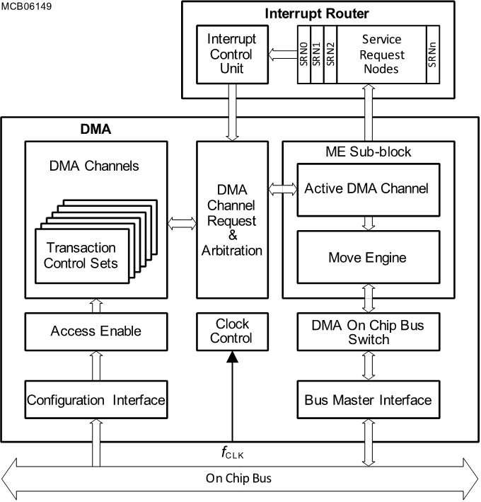
The DMA is configured by software over the FPI_SIF interface and implements access protection to provide functional freedom from interference between different applications using the DMA. Each DMA channel stores the context of an independent DMA operation in a transaction control set (TCS). Each application can configure and use one or more DMA channels. The DMA channels can be triggered by software requests, through hardware requests coming from the interrupt router (IR), or through other internal triggers. All DMA channels with pending DMA requests are then arbitrated so they can begin processing on one of the available move engines (MEs). DMA moves generated by the MEs result in read and write transactions being sent out through the DMA master agents FPI_MIFx and SRI_MIFx onto the system interconnect. Each DMA channel can be configured to generate interrupts to the IR for completion and other events on the CHc interface. The DMA resource partitions (RPs) can also generate error interrupts to the IR on the ERRr interface. The DMA also implements interfaces to various infrastructure components for clocks, resets, sleep and shutdown requests. It implements debug and trace functionality through the interfaces with the DEBUG and TRACE functional blocks. The DMA also generates alarms for safety relevant events to the SMU.