Flexible Peripheral Interconnect (FPI)
System-on-chip communication is based on two on-chip bus protocols:
- Shared resource interconnect (SRI, cross-bar based connection, 64-bit data bus)
- Fast peripheral interconnect (FPI, multi-master connection, 32-bit data bus)
The SRI connects the TC1.6 CPUs, the most important peripheral devices with high bandwidth, and the DMA module with its local resources for command calls and data accesses. The FPI connects the high-speed peripherals, for example, TC1.6 CPUs, DMA, to the medium and low-bandwidth peripherals.
This document covers the topics:
- FPI bus architecture
- FPI bus instances (SPB, BBB)
- FPI bus operation
Feature list
The FPI bus connects the on-chip peripheral functional units with the processor subsystem. The FPI bus is designed to allow the on-chip functional units to quickly acquire it and transfer data quickly. The low setup overhead of the FPI bus access protocol guarantees fast FPI bus acquisition, which is required for time-critical applications. The FPI bus is designed to support high transfer rates. Pipelining of transmissions is supported by handling the request, address, and data phases of transmissions in parallel, allowing the FPI bus to operate close to its peak bandwidth.
Features of the FPI bus include:
- Optimized for high-speed and high-performance
- Support of multiple bus masters and pipelined transactions
- 32-bit wide address and data buses
- 8-, 16-, and 32-bit data transfers
- 64-, 128-, and 256-bit block transfers
- Slave-controlled wait state insertion
- Timeout detection and handling
- Support of atomic CPU operations, for example, LDMST, ST.T, SWAP.W, CMPSWP, and SWPMSK
- Flexible arbitration schemes (priority, one round-robin group, starvation prevention)
- Starvation prevention mechanism taking care that even low-priority requests will be granted after a configurable number of arbitration cycles, permanently enabled
- Default slave (takes over transactions to not implemented address)
- Debug support (captures transaction information in case of a timeout or bus error)
- Address phase includes master TAG ID and supervisor mode information
- All slave modules implemented with a TAG ID based access protection that provides a generic write protection for the control registers (SPB/BBB: write protection only)
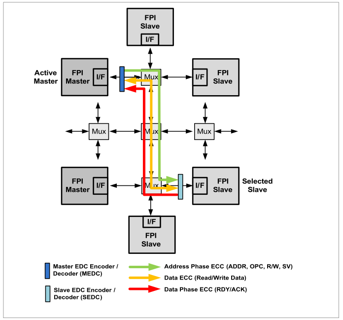
- Information integrity support covering SPB/BBB address phase signals, transmitted read/write data, and control signals
- SPB/BBB address phase includes supervisor mode information (covered by the FPI information integrity support)
The functional units of the device are connected to the FPI bus via FPI bus interfaces. FPI bus interfaces act as bus agents that request bus transactions on behalf of their functional unit or respond to bus transaction requests.
There are two types of bus agents:
- FPI bus master agents can initiate FPI bus transactions and can also act as slaves
- FPI bus slave agents can only react and respond to FPI bus transaction requests to read or write internal registers of slave modules as, for example, memories
When an FPI bus master attempts to initiate a transfer on the FPI bus, it first signals a request for bus ownership to the bus control unit (SBCU). If the SBCU grants bus ownership, an FPI bus read or write transaction is initiated. The unit affected by the transaction becomes an FPI bus slave and responds with the requested action. Some functional units only work as slaves, while others can work as both master and slave on the FPI bus. FPI bus arbitration is performed by the bus control unit (SBCU) of the FPI bus. In the event of bus errors, the SBCU generates an interrupt request to the CPU and provides the CPU with debugging information about the actual bus error.
Functional description
The flexible peripheral interconnect (FPI) is a multi-master interconnect with a 32-bit interconnect that supports 8-, 16-, 32-, 64-, 128-, and 256-bit data transfers as well as atomic read-modify-write transactions. Multi-master interconnect means that exactly one data transfer can be carried out between the connected function blocks at any one time. The FPI connects the high-speed function blocks, such as the TC1.8 CPUs and DMA modules, with the medium and low-bandwidth system and communication function blocks.
The TC3x system interconnect architecture defines multiple FPI interconnect instances where each FPI interconnect instance provides a dedicated FPI bus control unit (BCU):
- SBU related to the system peripheral interconnect (SPB)
- CBCU related to the converter peripheral interconnect (CPB)
- COMBCU related to communication peripheral interconnect (COMPB)
- RBCU related to the radar control peripheral interconnect (RCB)
- CSBCU related to the cyber security peripheral interconnect (CSPB)
- TBCU related to the tool peripheral interconnect (TPB)
Function blocks (FB) can be connected to an FPI connection via an FPI slave interface, also known as a slave agent, and via an FPI master interface, also known as a master agent. An FPI interconnect enables the connected master agents to access the address range of the connected slave agents. In contrast to the SRI interconnect, which provides a cross-bar connection that supports parallel access between the connected master and slave agents, an FPI interconnect is a shared interconnect in which all master and slave agents share the connections. An FPI connection is therefore limited to only one connected master agent accessing one connected slave agent at a time.
There are two types of agents that are used to connect function blocks to an FPI interconnection:
- The FPI master agent can request access to the FPI connection and start an FPI transaction if it is authorized by the local BCU arbitration function
- FPI slave agents can only react and respond to FPI transactions initiated by FPI master agents to read or write internal registers of slave modules and, for example, memory
When an FPI master agent attempts to initiate a transaction on the FPI, it first reports a request for connection ownership to the local BCU. If the BCU agrees to the master agent, it becomes the active master agent and begins the read or write transaction, which consists of one or more address and data phase sequences. The slave agent addressed by the address phase of the transaction becomes the active FPI slave agent, which responds either with the requested data transfer or with a transaction error.
The arbitration of the FPI interconnection is carried out by the BCU of the FPI. In the event of a transaction error, the BCU reports an alarm to the safety management unit (SMU). It can also generate an interruption request and collect information about the transaction that led to the transaction error.