Generic Timer Module (GTM)
The GTM module is a timer designed for applications requiring numerous inputs and outputs, such as powertrain or braking systems. This module can drive various types of Pulse Width Modulation (PWM) signals without dead time. Additionally, it can capture signals from ports and process them using its local computing unit. Moreover, it is capable of receiving signals from other parts of the device's infrastructure and controlling them.
Feature list
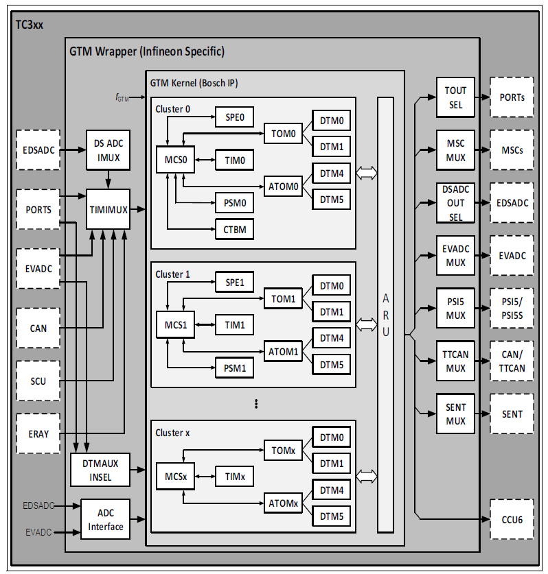
The GTM module consists of two main parts:
The GTM IP - designed by Bosch
- The GTM IP consists of numerous submodules, providing a wide range of functionalities to cater to the most common applications for a timer module
- The GTM Wrapper1 - designed by Infineon
The following is a list of some of the most important GTM IP features found in the submodules:
- Central/Edge aligned PWM generation (TOM/ATOM)
- Dedicated module for asymmetric dead time generation (DTM)
- Dedicated support for DC-DC phase shift operation (DTM)
- Logical combination of digital signals (DTM)
- Provide a common time base for a system (TBU)
- Multiple capture/compare of external signals and combination with time stamps (TIM/ATOM/TBU)
- Complex digital signals generation (PSM, ATOM, MCS)
- Digital signals filtering and characterization (TIM)
- Input signal measurement and timeout detection (TIM)
- BLDC motor control using Block commutation mode (SPE, TIM, TOM)
- Engine angle clock for engine management applications (DPLL, TIM, MAP, TBU)
- Injection/Ignition pulses generation with dedicated HW support (DPLL, ATOM, MCS)
- Programmable RISC-like cores to offload the CPU (MCS)
- Automatic data sharing between GTM modules without CPU/DMA (ARU, BRC)
- Configurable operating frequency up to 200 MHz (CCM, CMU)
Functional description
This document is a short specification for the generic timer module (GTM). It contains a module framework with submodules of different functionality. These submodules can be combined in a configurable way to form a complex timer module that serves different application domains and different classes within an application domain. Due to this scalability and configurability, the timer is referred to as generic.
Scalability and configurability are reached with an architecture philosophy where dedicated hardware submodules are located around a central routing unit (called advanced routing unit (ARU)). The ARU can connect the submodules in a flexible way. The connectivity is software programmable and can be configured during runtime. Nevertheless, the GTM is designed to unload the CPU or a peripheral core from a high interrupt load. Most tasks within the GTM - once set up by an external CPU - can run independently and in parallel with the software. There may be special situations where the CPU needs to intervene, but the goal of the GTM design was to minimize these situations.
The hardware submodules have special functions, for example, there are timer input modules with which incoming signals can be recorded and characterized together with a time concept. Complex functions can be realized by combining several submodules via the ARU. For example, the signals characterized at an input module can be forwarded to a signal processing unit, where an intermediate value can be calculated via the incoming signal frequency. The modules that help to implement such complex functions are referred to as infrastructure components. These components are available in all GTM variants. However, the number of these components may vary from device to device.
Other submodules have a more general architecture and can fulfill typical timer functions, for example, there are PWM generation units. The third class of submodules is those that fulfill a specific functionality for a specific application domain, for example, the DPLL for motor management applications. A fourth group of submodules is responsible for supporting the implementation of safety functions to fulfill a specific safety level. The ICM module is responsible for interrupting services and defines the fifth group. Each GTM is therefore built with submodules from these four groups. The application class is defined by the number of components of these submodules that are integrated into the implemented GTM.
GTM forms a generic timer platform that serves different application domains and different classes within these application domains. Depending on these diverse application domain requirements, multiple device configurations with different numbers of submodules (that is, ATOM, BRC, MCS, PSM, SPE, TIM, TOM, DTM) and different numbers of channels per submodule (if applicable) are possible. The parameter storage module (PSM) is only a virtual hierarchy and consists of the submodules F2A, FIFO, and AFD. The cluster dead time module (CDTM) is also a virtual hierarchy and consists of up to six DTM modules. It depends on the GTM device configuration that of the six DTM instances are available. In general, the first four DTM modules within a CDTM[n] hierarchy are connected to the outputs of the TOM instance [n] of cluster [n], the other two DTM instances are connected to the outputs of the ATOM instance [n] of this cluster [n].
The central component of the GTM is the advanced routing unit (ARU), around which most of the submodules are arranged and connected. Together with the broadcast (BRC) and the parameter storage module (PSM), this ARU forms the infrastructure part of the GTM. The ARU is able to route data from a connected source submodule to a connected target submodule. The routing is done in a deterministic way with a round-robin scheduling scheme for the connected channels receiving data from the ARU and with a worst-case round-trip time.
The routed data word size of the ARU is 53 bits. The data word can be logically divided into three parts. Bits 0 to 23 and bits 24 to 47 typically contain data for the operating registers of the GTM. This can be, for example, the duty cycle and the period duration of a measured PWM input signal or the output characteristic of an output PWM to be generated. Another possible content of Data0 and Data1 can be two 24-bit values of the GTM time bases TBU_TS0, TBU_TS1 and TBU_TS2. Bits 48 to 52 can contain control bits to send control information from one submodule to another. These ARU control bits (ACB) can have different meanings for different submodules. It is also possible to route data from a source to a destination and the destination can later serve as a source for another destination. These routes through the GTM are referred to below as data streams.
The signals are transmitted to the GTM at the timer input modules (TIM). These modules are able to filter the input signals and record additional information. Each channel can, for example, measure the pulse high or low times and the period of a PWM signal in parallel and forward the values to the ARU for further processing. The internal operating registers of the TIM submodule are 24 bits wide. The clock management unit (CMU) serves up to 13 different clocks for the GTM and up to three external clock pins. It acts as a clock divider for the system clock. The counters implemented in other submodules are typically controlled by this submodule. The CMU clocks are implemented as enable signals for the counters, while the entire system runs with the global GTM clock SYS_CLK.1. This global clock typically corresponds to the microcontroller bus clock to which the GTM-IP is connected and should not exceed 100 MHz due to the power dissipation of the transistors used to implement the GTM.
Signal outputs are generated with the dead time module (DTM), the timer output modules (TOM) and the TOMs connected to the ARU (ATOM). Each TOM channel is able to generate a PWM signal at its output. Thanks to the integrated shadow register, it is even possible to generate complex PWM outputs with the TOM channels by operating the parameters with the CPU. In addition, each TOM submodule can integrate functions for controlling a BLDC motor. This BLDC support is set up together with the TIM and sensor pattern evaluation (SPE) submodule. The ATOMs provide the additional functionality of generating complex output signals without CPU interaction by providing these complex waveform characteristics through other submodules connected to the ARU, such as the PSM or multi-channel sequencer (MCS). Together with the MCS, the ATOM can generate any predefined output sequence at the GTM output pins. The output sequence is defined by instructions located in the RAM connected to the MCS submodule. The instructions define the points at which an output signal should change or react to other signal inputs. The output points can be one- or two-time stamps (or even angle stamps in the case of a motor management system) provided by the TBU.