Controller Area Network (CAN) Interface
The MCMCAN implements Bosch M_CAN as CAN nodes. The M_CAN performs communication according to ISO 11898-1 and according to ISO 11898-4 (Time-triggered communication on CAN). The M_CAN provides all features of time-triggered communication specified in ISO 11898-4, including event synchronized time-triggered communication, global system time, and clock drift compensation. In addition the M_CAN supports classical CAN and CAN FD communication according to ISO 11898-1. The CAN FD option can be used together with event triggered and time-triggered CAN communication.
The figure shows the AURIX™ TC3xx platform specific implementation details and interconnections of the MCMCAN module. The I/O lines of the MCMCAN module (two I/O lines of each CAN node) are connected to the ports. The MCMCAN module is also supplied by clock control, interrupt control, and address decoding logic.
Feature List
The following are features of the MCMCAN module:
ISO 11898-1, -4
CAN FD with up to 64 data bytes supported
TTCAN protocol level 1 and level 2 completely in hardware
Event synchronized time-triggered communication supported
CAN Error Logging
AUTOSAR optimized
SAE J1939 optimized
Improved acceptance filtering
Two configurable Receive FIFOs
Separate signaling on reception of High Priority Messages
Up to 4 CAN nodes
Direct Message RAM access for Host CPU
Multiple M_CANs share the same Message RAM
Programmable loop-back test mode
Maskable module interrupts
8/16/32-bit Generic Slave Interface for connection customer-specific Host CPUs
Features offered by each M_CAN node:
Two configurable Receive FIFOs
Separate signaling on reception of High Priority Messages
Up to 64 dedicated Receive Buffers
Up to 32 dedicated Transmit Buffers
Configurable Transmit FIFO
Configurable Transmit Queue
Configurable Transmit Event FIFO
Delta to AURIX™
MCMCAN is the new CAN interface, in which the user interface to the module is different than the previous MultiCAN+ CAN interface.
Notable changes are:
Message objects are replaced by configurable Message RAM
Support of debugging on CAN
Functional description
An overview of an MCMCAN module is shown in the figure. The MCMCAN supports following variants of CAN communication protocols:
Classical CAN and CAN FD according to ISO 11898-1
Time Triggered CAN according to ISO 11898-4
The MCMCAN consists of Bosch M_CAN as CAN nodes and a wrapper around the M_CAN called user interface. M_CAN provides the following functionality:
CAN protocol controller
Receive and transmit time stamp generation
Transmit handler
Receive handler
Figure 1. MCMCAN block diagram
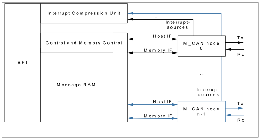
The user interface of MCMCAN provides the following functionality:
A configurable message RAM to store the message to be transmitted or received. The message RAM is shared by all CAN nodes within a MCMCAN module
Grouping and signalling of interrupts through Interrupt Compression Unit (ICU)
Clock selection and generation through Clock Control Block
Access protection through BPI
Timer based transmission of CAN frame and timeouts for reception of CAN frames
The functionality of MCMCAN is devided into three different sub-sections:
User Interface
M_CAN functionality
TTCAN operation
MCMCAN User Interface
The MCMCAN User Interface describes clock generation, grouping of interrupts, external connections to the module and IO configurations.
MCMCAN Clockpaths
The MCMCAN module clock inputs are connected to the Clock Control Unit (CCU). The CLC setting supplies the global module registers with its clocks. To supply the M_CAN nodes with the corresponding clocks, the MCR.CLKSELi registers have to be set. The asynchronous clock as well as the synchronous clock of each single M_CAN node can be switched on/off via MCR.CLKSELi register bitfields.
TTCAN operations
Time-Triggered Controller Area Network (TTCAN) is an extension of the standard Controller Area Network (CAN) protocol, designed to provide deterministic and time-triggered communication in distributed systems. Standard CAN operates on an event-triggered basis, where messages are transmitted based on priority and bus availability, potentially leading to unpredictable transmission delays. TTCAN addresses this by introducing a time-triggered mechanism, ensuring predictable message transmission times.
The key features of TTCAN address functions like time division into basic cycles, reference messages and time synchronization, different types of time windows, system matrix configuration, or different implementation levels. By integrating these features, TTCAN offers deterministic communication, reduced latency jitters, and improved bandwidth utilization, making it particularly suitable for real-time applications in automotive and industrial automation sectors.