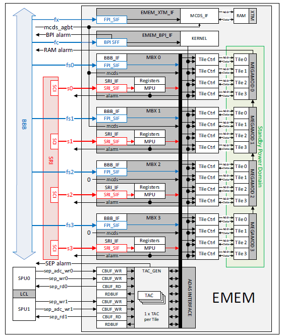
Extension Memory (EMEM)
The EMEM contains RAM blocks (EMEM Tiles) which can be alternatively used for application (ADAS), calibration or trace data storage. The EMEM has interfaces to MCDS, SEP, SRI and BBB.
Feature list
The EMEM has the following features:
- Software may configure the operation mode of each individual EMEM Tile
- 16 Kbyte XTM for trace data only
- Standby power supply for TCM and XCM
The EMEM supports the following applications:
- Application/ADAS data
- Program code
- Calibration data
- Measurement data
- Trace data
- ED prolog code
Functional description
Two different types of EMEM modules are available:
- TCM may be split into Application/ADAS, Calibration and Trace Memory parts
- XCM may be used as Application/ADAS or Calibration Memory only
The XTM is used for tracing without reducing the Common Memory. The XTM has two 8 Kbyte Tiles, which is sufficient for continuous trace over DAP.
Devices with AGBT use XTM0 and XTM 1 as an AGBT Trace buffer.
Isolation logic
The EMEM configurations are instanced on AURIX™ TC3xx devices. The instances isolation logic is implemented around each EMEM module to prevent any power drain via powered gate outputs into the unpowered section of the device. The logic isolating the inputs into the standby domain are controlled by the power on reset (PORST). The logic isolating the outputs from the standby domain are controlled by the standby locked mode signal.
EMEM modes
The EMEM shall be in one of the following modes:
- Standby locked mode
- Locked mode
- Unlocked mode
RAM isolation
The RAM shall be isolated prior to removing the power supplies. This assures that spikes or uncontrolled signal patterns applied to its interfaces during power cycling of the logic will not corrupt the content. It is not allowed to remove the EMEM isolation logic when VDDSB is not powered since this will damage the chip. Software and tools may monitor the availability of VDDSB. If VDD is powered and VDDSB is not powered, the EMEM may report ECC errors.
Locked mode
After EEC reset, the EMEM is in Locked Mode. If the EMEM is in Locked Mode then accesses from chip interfaces (MCDS, SEP, SRI and BBB) are treated as errors. Software shall configure the SBRCTR register to change the EMEM mode. Both unlocked mode and the standby locked mode may only be entered from locked mode.
Standby locked mode
As long as the standby power supply (VDDSB) is powered, the content of the RAM shall be retained.
On chip bus accesses to the EMEM Core CLC, ID, SBRCTR registers and EMEM Module registers are serviced normally. All other register and RAM accesses are terminated with error.
Changing the EMEM
mode
The EMEM mode shall be changed as follows:
Transition from locked mode to unlocked mode
To enter unlocked mode, software shall write the following sequence to the SBRCTR register:
- 0000 0002H,
- 0000 0006H,
- 0000 000EH
If software writes any other value to SBRCTR before the complete sequence is written, then the state machine shall be reset. To enter Unlocked Mode, the complete sequence shall be started again. If software writes to another register, the state machine sequence checking shall not be influenced. The current state is signalled with bit SBRCTR.STBLOCK.
Transition from unlocked mode to locked mode
To enter Locked Mode from Unlocked Mode, software shall write 0000 0090H to the SBRCTR register.
Transition from locked mode to standby locked mode
If the EMEM is in locked mode then standby locked mode shall be entered by setting the PORST pin low and removing all supplies apart from VDDSB. Setting PORST low shall maintain the isolation of the standby domain after the supplies are removed.
Transition from standby locked mode to unlocked mode
The transition from standby locked mode to unlocked mode shall be performed with the following steps:
- The PORST pin shall be active
- All the power supplies shall be stable
- After the PORST release the EMEM shall be in locked mode
- Software shall check the standby power domain is available (SBRCTR.STBPON = 1B)
- Software may configure unlocked mode transitioning from locked mode to unlocked mode
- The isolation logic around the standby domain shall be switched off
Tile modes
After EEC reset, all EMEM Tiles shall be in Unused Mode. Software shall configure the TILECONFIG register to assign TCM tiles to Common Memory, Trace Memory or Unused mode and XCM tiles to Common Memory or Unused Mode. An EMEM Tile assigned to Trace Memory shall not be reconfigured for Common Memory directly, or vice versa, but only after having been intermediately set to Unused Mode. An EMEM Tile assigned to Common Memory shall initially be in Application Mode, and an EMEM Tile assigned to Trace Memory shall initially be in MCDS Mode. The assignment of each Tile is indicated by the TILESTATE register.
Each EMEM Tile assigned to Common Memory shall be individually configured between Application Mode and Tool Mode. The status of Tiles assigned to Common Memory is indicated by the TILECC register. Each EMEM Tile assigned to Trace Memory shall be individually configured between MCDS Mode and Tool Mode. The status of Tiles assigned to Trace Memory is indicated by the TILECT register. If an EMEM Tile is in Unused Mode, then the settings in the TILECC and TILECT registers have no effect.