AN0001 AURIX™ TC3xx functional safety (FuSa) in a nutshell
32-bit TriCore™
AURIX™ TC3xx microcontroller
About this document
Scope and purpose
As requirements from functional safety standards in automotive, industrial and other fields are a challenging subject, this document intends to provide a first set of guidelines for users who are unfamiliar using the AURIX™ TC3xx microcontroller unit (MCU) in a functional safety scope.
This application note is part of a series of document named “FuSa in a nutshell” and listed in
5
Intended audience
This application note is intended for all those evaluating the AURIX™ TC3xx MCU, including functional safety engineers on the customer side and application engineers. This includes designers of safety-related systems who:
Are new to functional safety
Want to know more about functional safety (also called “FuSa”) applications
Want to understand in principle how functional safety can be implemented with hardware support
Are looking for functional safety details that cannot be found in the MCU user manual
Structure of the document
This document intend to illustrate AURIX™ TC3xx main blocks and introduce the built-in safety mechanisms that are offered.
Disclaimer
Application use cases, if any, are for training purposes only and are not to be taken as a blueprint for developing such units.
AURIX™ TC3xx MCU – functional safety introduction
shows an overview of the functional blocks available on the AURIX™ TC3xx platform. A clear distinction is made through the colors between cores, memories, peripherals and special features of the product family.
Figure 1. Main features of the AURIX™ TC3xx family
As AURIX™ TC3xx is developed for functional safety use cases, each functional block (apart from a few peripherals) is built to prevent a fault from leading directly to a safety goal violation or to remain latent.
shows a non-exhaustive overview of the hardware safety measures available for each functional block of the AURIX™ TC3xx platform. The main safety features are described in the subsequent subsections.
Figure 2. Overview of the main safety features of MCU blocks
Safety of MCU infrastructure blocks
To execute any safety application software, it is essential to ensure the correct configuration and monitoring of the MCU infrastructure.
By MCU infrastructure, it means:
Common functional blocks: Considered as possible common-cause failure initiators
Access protection features: Provide freedom from interference between HW/SW elements More information can be found in
6
Error management and reporting: Provide a transition to the safe state when a fault is detected (see Section
MCU reaction plan – SMU
for more information)
Common functional blocks
Blocks such as the power management system (PMS), clocks, ports, reset and others that are common to all basic functionalities of the MCU are considered always active. They are usually involved in the nominal (also called “mission”) functions and the monitoring functions of AURIX™ TC3xx. Faults in any of these blocks are considered safety-critical and must be detected. In the following sections, an overview of the safety features that are available in these functional blocks is provided.
Power management system (PMS)
The PMS provides the power infrastructure, generates supply voltages using internal voltage regulators, facilitates power distribution and manages system power modes. Monitoring the supply voltages is the main safety activity implemented in the PMS. This consists of detecting overvoltage or undervoltage events at the different supply voltages.
Power built-in self-test (PBIST)
This test is carried out at reset (Cold PORST). More information can be found in
6
. for details on various resets). The goal is to ensure that external power supplies reach a minimal value before reset release. The MCU will remain in a reset state while the defined voltage thresholds are not exceeded.
Primary undervoltage monitor
The primary voltage monitor triggers a reset (Cold PORST) if VEXT, VDDP3 or VDD drops below the lowest possible threshold for the correct operation of the system. Reset threshold values are defined in the product datasheet.
Secondary overvoltage and undervoltage monitors
The secondary voltage monitor triggers alarms in case of an overvoltage or undervoltage event in any of the supply rails (that is, VEXT, VDDP3, VDD, VEVRSB and VDDM). These thresholds are to be configured by the user.
Note:
VEVRSB and VDDM are not monitored by the primary monitor because it is assumed that the secondary monitors are reliable when VEXT, VDDP3 and VDD are within the operating range.
Note:
External supervisors for VEXT overvoltage are supplied at the system level; for example, see Section
Error-correcting code technique
.
Figure 3. Power supply rail internal primary and secondary safety monitors
Clocking system
The clocking system includes the clock generation unit (clock source), clock scaling (PLLs), clock distribution (CCU) and individual clock configurations (for each MCU peripheral). Since the clock signals are distributed to all peripherals, the clocking system is a potential source of common-cause failures. Therefore, fault detection coverage of this block is an important part of the safety measures that are implemented in AURIX™ TC3xx devices.
Hardware measures are implemented to detect faults in all submodules of the clocking system. The main measure is to compare the frequencies derived from an independent clock source against the operating frequency to be protected.
Clock source
The backup clock (internally generated) and the external crystal oscillator (XTAL OSC) are monitored via a watchdog function. An alarm is generated if the number of backup clock cycles within a window of 512 f
PLL0
clock cycles (derived from the XTAL OSC) exceeds a configurable value.
Clock scaling (PLLs)
The output of PLLs output is monitored by comparing it against a diverse clock (the backup clock); the backup clock output is monitored by f
PLL0
. A "clock alive" alarm is generated if the monitored clock is below an expected value.
Figure 4. Clock source and clock scaling built-in safety mechanisms
The PLL has a lock detection feature that differentiates between stable and unstable circuit behavior. The PLL may unlock because of a break in the crystal or ceramic resonator or the external clock line. In such a case, a safety management unit (SMU) alarm event is generated.
Clock distribution (CCU)
Clock signals distributed to the individual peripherals must be monitored by the application software. The idea is to compare safety-related peripheral clocks against clocks that are generated from different PLLs, for example:
Such a plausibility test detects the wrong settings or states of the clock dividers in the CCU logic.
Figure 5. Clock distribution protected by plausibility check
Clock configuration
In all clocking system subparts, safety-related configuration registers (SFRs) are protected via safety flip-flop (SFF) mechanisms. Safety flip-flops are special flip-flops that implement a hardware mechanism capable of detecting bit flips within the protected registers, thus preventing single-point faults. Alarms will be generated in the event of bit-flip events.
System control unit (SCU)
The SCU is a module that includes several central infrastructure submodules, such as the reset control unit, emergency stop, watchdog timers and trap generator (see Section
Interrupts and trap handling
). A set of protection mechanisms (SFFs, signal redundancy and so on) is implemented in the SCU to detect transient or permanent faults that may lead to severe malfunction of the MCU.
The SCU implements the following HW features that are typically required for a safety application:
Watchdog timers:
These timers monitor access to protected SFRs via Endinit or safety Endinit protection (each CPU has a watchdog timer; in addition, a safety watchdog timer is available for shared resources)
Emergency stop (ES):
The emergency stop feature provides a fast reaction to an alarm without the intervention of the software. As a reaction to the emergency event, selected output ports can be immediately placed into a defined state (for example, bring the actuators into a known state). An emergency stop can be triggered by the following:
A transition on the port that is configured as the emergency stop input
An alarm event or command from the SMU that is configured to generate a port emergency stop
The emergency stop control logic for the ports operates in two modes:
Synchronous mode (default): The emergency case is activated by hardware and released by software
Asynchronous mode: Both the activation and release of the emergency case are done by hardware
Die temperature sensor
To avoid the MCU working outside of the expected temperature range, two temperature sensors are implemented in the AURIX™ TC3xx device. This feature can be used as an additional safety mechanism because it enables the generation of an early warning whenever the die temperature is too close to the boundaries of the operating range. Both sensors are located near areas that are the warmest areas of the product. The first instance (PMS_DTS) is located close to the PMS. The second instance (DTS_Core) is located close to the CPU cluster. Each sensor will detect whether the temperature is within the specified limits and set temperature underflow/overflow alarms accordingly.
Safety of processing blocks
Safe computation – CPU
The TC3xx family utilizes the TC1.62P core hardware, which is based on the TC1.6P core with enhancements in memory distribution, protection and other aspects. Additionally, up to four CPUs are protected by a lockstep mechanism, which allows them to run up to ASIL-D or SIL 3 applications without the need to integrate cyclic software-based self-tests for the CPU.
CPU memory and temporal protection
The CPU offers several HW measures for protection of memory and module resource accesses (registers), as well as timer-based mechanisms for detecting timing violations of the SW.
Lockstep CPU
Depending on the device variant, an AURIX™ TC3xx offers up to four lockstep CPUs. The lockstep (LS) CPU monitoring is based on hardware redundancy with online monitoring of the outputs. The lockstep monitoring function compares the outputs of the master and the checker cores and signals a fault to the SMU for appropriate action.
The monitoring function temporarily separates the cores by inserting delays in the signal chain to avoid an external disturbance that affects both cores in the same way and therefore goes undetected by the lockstep mechanism. To achieve this, the redundant core inputs and the master core outputs fed to the comparators are delayed by two clock cycles, realigning the two signals. The lockstep core has no effect on the nominal operation.
Figure 6. Scheme for an arbitrary node comparator (A) of a lockstep core and its fault injection (B)
The cores equipped with a lockstep also have a continuously running background self-test of the lockstep comparator. The self-test function will inject faults into both inputs of each of the monitored nodes and verify that the fault is correctly detected by the monitoring logic.
shows a simple representation of an arbitrary node comparator and the fault injection mechanism, which is highlighted in green.
All CPU functions are covered by the following lockstep system:
Exception handling
Instruction fetch and execution
Data movements from internal RAM to the core or bus interface
Non-lockstep CPU
The non-lockstep CPU has an identical architecture compared to the lockstep CPU, but it does not include the checker core and the comparator output logic. While the performances of the non-lockstep and lockstep CPUs are the same, the non-lockstep CPU cannot rely on redundant hardware elements. Therefore, a software-based mechanism named software-based self-test (SBST) is required for covering single-point faults and latent faults of the CPU itself.
System timer module (STM)
The system timer is a free-running 64-bit timer that is enabled immediately after an application reset and can be read by the application software. Each CPU has a dedicated STM. The system timer is fundamental for the operating system and task scheduling. It can be configured to generate a compare-match interrupt service routine (ISR) by using dedicated registers. The STM is not part of the duplication area of the CPU, so no specific hardware is dedicated to monitoring the correct behavior of the timer. In cases where the STM is used in safety-relevant applications, the application SW performs plausibility checks using an independent timer.
Error-correcting code technique
Error-correcting code (ECC) is a technique that adds a number of check bits to a message or data, allowing it to detect and correct a limited number of errors. In this scope, the minimum number of bit flips required to change one valid codeword into another valid codeword is called the “hamming distance”. Typical ECCs, such as hamming codes, can detect with certainty up to 2-bit errors and correct 1-bit errors. Hamming codes are used in AURIX™ TC3xx SRAMs. In this case we have single-bit error correction and dual-bit error detection (SECDED). Another type of ECC, such as BCH codes, can be designed to correct multiple-bit errors. BCH codes are used in AURIX™ TC3xx PFlash with dual-bit errors correction and three-bit error detection (DECTED). For DECTED, a hamming distance of six is required.
Figure 7. ECC concept
CPU RAMs
Each CPU utilizes different RAM blocks as local memories, which are represented in
Figure 8
and listed as:
Data Scratch Pad RAM (DSPR)
Program Scratch Pad SRAM (PSPR)
Data Cache (DCache)
Program Cache (PCache)
Distributed Local Memory Unit (DLMU)
Local PFlash Bank (LPB)
Figure 8. Processor core, local memory and connectivity
The processor core connects to these memories and to the following bus interfaces (where these are implemented):
SRI Slave Interface (x2)
SRI Master Interface
SPB Master interface
The CPU RAM can be affected by transient or permanent faults and implements the same safety mechanisms common to all SRAM blocks. See Section
Error-correcting code technique
for more information.
The RAMs of the lockstep CPU are not replicated as part of the lockstep mechanism, but the program memory interface (PMI) and data memory interface (DMI) within the lockstep CPU’s RAM instances , including ECC encoding and decoding, are part of the area of duplication. Lockstep CPU memories are therefore classified as ASIL-D, allowing the user to execute ASIL-D software from a lockstep CPU using any combination of local CPU memory or the memories of another lockstep CPU.
Non-lockstep CPU memories inherit the ASIL-B level from the non-lockstep CPU. If users want to perform ASIL-D read/write operations by using a non-lockstep CPU memory from a lockstep CPU, the system integrator must take care of monitoring data corruption. This means monitoring the data (stored in the CPU.PSPR, CPU.DSPR or CPU.DLMU) of non-lockstep CPUs by using information redundancy.
Non-volatile memory (NVM)
As shown in
Figure 9
, the MCU features memory resources that are distributed to multiple locations. In particular, the NVM is dedicated to storing data or programs in flash memories. It is composed of the following parts:
Data flash:
Flash banks are used to store application data. Two banks are available (DF0 and DF1)
Program flash:
Flash banks are used to store application SW code or constant data. One bank with local access is available per CPU
User configuration blocks (UCB):
This block is used for user configuration of the device. It is part of DF0
Flash standard interface (FSI):
Executes erase, program and verify operations on all flash memories
Configuration sector (CFS):
This block contains device-specific settings that are not accessible by the user
BootROM (BROM):
Contains the firmware executed by the device at start-up before user-defined software can be executed
DMU:
Interface the FSI and PFI with data flash, UCB and CFS
Program flash interface (PFI):
Provides a fast connection between each program flash bank and its CPU
Figure 9. Nonvolatile memory subsystem
Monitoring of NVM
The content of PFlash banks is crucial because it contains the code executed by the CPU. Any fault leading to transient or permanent corruption of the PFlash content can lead to severe malfunctions that are not detectable by SW. Therefore, the NVM offers dedicated safety mechanisms for the monitoring of several failures affecting the PFlash. See Section
Error-correcting code technique
for more information.
Each 256-bit block is protected by an enhanced error detection code (EDC) and ECC logic that can detect up to 3-bit errors (TBE) and correct single-bit errors (SBE) as well as double-bit errors (DBE). In addition, a correctable bit address buffer (CBAB) is available to monitor the number and address of corrupted code words; each address is stored only once and an uncorrectable bit address buffer (UBAB) is present to store the address of an uncorrectable error.
To address the latent fault metric of the ECC logic, the PFlash ECC/EDC decoder is also monitored to detect failure modes of the ECC decoder. In addition to all these HW-based safety mechanisms, before starting to fetch safety-relevant code from a PFlash bank or upon every content update, the user application software will execute additional checks, such as a CRC of the full memory.
The nonvolatile memory also has a dedicated RAM for the FSI interface. The RAM can be affected by transient or permanent faults that can corrupt data and it is protected by the same safety mechanisms common to all SRAM blocks.
Distributed volatile memory
In addition to the volatile memories associated with each CPU, AURIX™ TC3xx has EMEM, LMU and peripheral RAMs. A few volatile memories are in a user-accessible memory range. Other memories are localized to the peripheral modules. RAMs are protected, for the most part, by the ECC mechanism. See Section
Error-correcting code technique
for more information. A few exceptions feature EDC only.
Finally, when the ECC detects the majority of the data corruption, the RAM has additional hardware safety mechanisms capable of detecting errors in the RAM address.
The RAM alarm concept is updated based on the expected fault reaction. From each RAM, the following three alarms are sent to the SMU:
Correctable-error alarm (CE): ECC correction is performed (that is, single-bit error correction)
Un-correctable error alarm (UCE): ECC detection (that is, double-bit error) or RAM address error detection
Miscellaneous error alarm (ME): Non-critical (latent) fault detection
EMEM
The EMEM is a dedicated memory that contains RAM blocks (EMEM tiles), which can be used for ADAS applications, calibration or trace data storage. The EMEM implements interfaces to SRI bus and BBB bus.
LMU
The LMU is an SRI-connected module providing access to volatile memory resources. Its primary purpose is to provide up to 256 KB of local memory for general-purpose usage.
SRAM
In this document, the various SRAMs are identified by the name of the functional block where the memory is located. In cases where one functional block has multiple SRAM instances, each memory has a unique identifier.
Functional block | Memory name |
|---|---|
CPU | DSPR |
PSPR | |
DTAG | |
PTAG | |
PCACHE | |
DCACHE | |
DLMU | |
SPU | CONFIG |
BUFFER | |
FFT | |
DMA | RAM |
GTM | RAM |
EMEM | RAM |
LMU | RAM |
PSI5 | RAM |
MCMCAN | RAM |
CIF | RAM |
HSPDM | RAM |
NVM | FSIRAM |
TRACE | RAM |
ERAY | RAM |
AMU | LMU_RAM |
GETH | RAM |
SDMMC | RAM |
SCR | RAM |
MCU function – ADAS
AURIX™ TC3xx supports advanced driver assistance systems (ADAS), a suite of technologies that help drivers stay safe on the road. The main blocks for ADAS are radar interface (RIF) and signal processing unit (SPU).
Radar interface (RIF)
The RIF acts as a 32-bit interface between internal or external ADC channels with the SPU module. The RIF is used in ADAS applications, where a high level of safety is required. Therefore, different parts of the RIF are monitored by HW safety mechanisms. The CRC redundancy technique is used for increasing fault coverage on configuration registers and the data interfaces with the monolithic microwave integrated circuit (MMIC) input stage and SPU output stage.
In the event of an error detection in the MMIC, the application SW performs additional actions to handle errors. Redundancy is applied to the RIF data path and safety mechanisms for increasing data integrity. RIF is a slave node of the FPI and is protected by common access protection safety mechanisms.
Figure 10. RIF overview
Signal processing unit (SPU)
The SPU is a semi-autonomous accelerator for performing Fast Fourier Transforms (FFTs) on data from one or more dedicated ADC interfaces. The SPU uses a three-stage streaming architecture to provide data pre-processing, FFT and data post-processing operations. The SPU uses the radar memory to store datasets and has internal buffer memories, which are used to store the data currently progressing through the processing pipeline.
The SPU is composed mainly of these parts:
SPU core: Computational unit for FFT calculations
SPU lockstep: Full redundancy in case the second SPU is used as a lockstep unit
SPU RAMs: Used for storing data (FFT, BUFFER) and configuration (CONFIG)
Figure 11. SPU architecture
The SPU offers several safety mechanisms that monitor the correct behavior of the unit. During runtime, the SPU configuration data and control flow of the operation are periodically checked. The SPU interfaces with RIF and EMEM are protected by hardware built-in safety mechanisms. The second SPU instance can be configured for full redundancy (comparison of control and data outputs), partial redundancy (comparison of control only) or no redundancy (no comparison).
In the event that SPU is not configured for full redundancy, additional external measures will be implemented at the SW level. A class of faults in the SPU can cause a deadlock in the SPU. A SW-based self-test (SBST) is provided and will detect and signal an error in case the test execution time takes longer than expected. The integrity of a few SPU safety mechanisms is monitored by other dedicated safety mechanisms. SPU is a slave node of the FPI and is protected by common access protection safety mechanisms.
SPU has three different types of RAM, each of which is dedicated to specific usage. Each RAM can be affected by transient or permanent faults that can corrupt data and have the same safety mechanisms common to all SRAM blocks.
Debug and test functionalities
Trace and debug modules are slave nodes of the FPI bus and are therefore protected by common access protection safety mechanisms.
Their functionality is disabled during operation. These blocks are protected by hardware safety mechanisms for providing freedom from interference, as described in
6
.
SRI and FPI busses
SRI bus
The SRI bus connects the CPU, the DMA module and other high-bandwidth requestors to high-bandwidth memories and other resources for instruction fetches and data accesses. The SRI interconnect supports parallel transactions between SRI masters and independent SRI slaves.
FPI bus
The FPI connects the high-speed peripherals (CPU and DMA) to the medium- and low-bandwidth peripherals. The AURIX™ TC3xx family has up to two FPI bus instances:
System peripheral bus (SPB): Main non-ADAS system and communication peripherals
Back bone bus (BBB): Emulation device-related and ADAS-related peripherals, available in ADAS/Emulation
SRI and FPI safety mechanisms
Any R/W operation of the MCU buses can be affected by several faults during the address phase or the data phase, resulting in incorrect or missing data, wrong addressing and so on. SRI and FPI slaves are protected by built-in hardware mechanisms against these possible faults.
MCU function – MCU communication
DMA
The DMA moves data from source modules to destination modules without the intervention of the CPU or other on-chip devices. A data move is defined by DMA configuration data. A DMA channel operation is initiated by a DMA hardware request or a DMA software request.
During DMA operations, transactions can be subject to permanent or transient faults that can affect the success of the data moves in several ways. In addition, the DMA source or destination address can be corrupted, resulting in the wrong data at the destination. Faults in the DMA move engine can lead to lost or delayed transactions. All these kinds of faults are addressed by internal hardware mechanisms.
Interrupts and trap handling
The TriCore™ architecture manual defines how the CPUs deal with interrupts and traps. The interrupt router (IR) module is responsible for scheduling service requests (also called interrupts) to the correct service provider. In the TC3xx architecture, internal peripherals, external hardware or application software can raise a service request. The service providers are all CPU’s and DMA.
The IR is a critical block since a fault in its logic, coming from hardware or software, can affect one or more service providers or the interrupt service routine (ISR). The IR is connected to all internal functional blocks, so a failure in a peripheral can generate malfunctions in the IR and propagate to the CPU, DMA or other peripherals. The correct behavior of the IR and its monitoring functions during runtime are crucial parts of the safety measures implemented in the TC3xx architecture. This is achieved by a combination of internal safety mechanisms built into the hardware and a few software checks.
Trap generation (TRAP) is a functionality of the SCU, which hosts a cluster of sub-modules that control various system functions. SCU trap generation determines which CPU receives a trap based on the trap event trigger. Interrupts can interfere heavily with the sequential execution of the program or be executed as an error reaction, while traps are generated when the core of the MCU detects an error.
Safety of application dependent blocks
Application-dependent blocks are parts of the MCU for which the fulfillment of the safety requirements requires a combination of application-level safety mechanisms and safety mechanisms provided by the MCU. Typical application dependent parts are peripheral modules participating in data-acquisition, actuation control and system-level communication. Correct and safe functionality of the MCU application-dependent blocks can be guaranteed with different techniques.
One of the most common techniques in SEooC peripherals is redundancy with comparison. When redundancy is applied, a dependent failure analysis (DFA) and coverage of common block functionality with additional controls are necessary.
In AURIX™ TC3xx, each identified cause of dependent failures is controlled by an adequate safety measure. One of these measures is the correct pin distribution, as explained in Section
Considerations on common-cause failures on pins and packages
.
Most of the application-dependent blocks use:
GTM modules for generating or capturing signals
ADC modules (EVADC or EDSADC) to perform analog signal acquisition
It is important to briefly introduce the GTM and ADC module concepts before exposing the application-dependent scenarios from a safety perspective.
Overview of GTM
Below is a summary representation of the generic timer module (GTM) that is often used in application-dependent use cases to implement digital acquisition and digital actuation. GTM TIM modules can acquire PWM, while GTM TOM or ATOM modules can generate PWM signals for digital actuation.
The safety mechanism is not in the resource itself (apart from access protection and SRAM ECC), but in the redundancy that is required as an assumption of use, which means implemented by the application engineer.
Figure 12. GTM summary representation
Overview of EVADC/EDSADC
Below is a summary representation of the enhanced analog-to-digital converter (EVADC) block and enhanced delta-sigma analog-to-digital converter (EDSADC) that are often used in application dependent use cases.
The safety mechanism is not in the resource itself (apart access protection) but in the redundancy that is required as an assumption of use.
There are four ADC types present in the MCU:
Delta Sigma: 13 ENOB (effective number of bits), ≤ 200 ksps
Primary SAR: 12-bit, ≤ 2.5 Msps
Secondary SAR: 12-bit, ≤ 1.4 Msps
Fast Compare: 10-bit, ≤ 5 Msps
Figure 13. ADC types
Safe analog acquisition
In AURIX™ TC3xx, the key to achieve the required safety level for analog acquisition is to have a redundant channel called the “monitoring” channel in addition to the functional channel, also known as the “mission” channel. Depending on the safety level required, the input pin for both channels (mission and monitor) will be the same or different. When selecting AD converters for mission and monitoring, the user should ensure to choose ADC blocks guaranteeing physical separation.
shows the case when redundant safety-related analog signals are delivered by the system and redundantly processed by internal resources of the ADC module. The results of the redundant processing are transported from the ADC module to volatile memory and compared by the CPU.
Figure 14. Simplified overview for safe analog acquisition
Note: The system integrator implements a check of the ADC reference voltage, either by an external monitor or by internally converting a known signal and compares the result with the expected value.
Safe digital acquisition
In AURIX™ TC3xx, the key to achieve the required safety level for digital acquisition is to have a redundant channel called the “monitoring” channel in addition to the functional channel, also known as the “mission” channel. Depending on the safety level required, the input pin for both channels (mission and monitor) will be the same or different.
Additionally, regarding the internal peripherals to be used for mission and monitoring, different combinations are possible using independent TIM (timer input) channels of the GTM block or a TIM channel and a “diverse” input timer from an independent peripheral (for example, using CCU6, which is an independent timer module). The CPU reads and compares the results of the signal measurement.
Figure 15. Simplified example of digital acquisition using two independent TIM channels of GTM
For digital acquisition, it is recommended to avoid the use of adjacent pins to prevent common-cause failures of the ports and package (see Section
Considerations on common-cause failures on pins and packages
).
Safe digital actuation
In AURIX™ TC3xx, the key to achieve the required safety level for digital actuation is to have a redundant channel called the “monitoring” channel in addition to the functional channel, also known as the “mission” channel. When selecting internal peripherals to be used for mission and monitoring, different combinations are possible using independent timer output channels and comparing them or reading back. For example, a GTM output timer using a GTM input timer and comparing these two signals.
When a GTM output resource (TOM or ATOM channel) is used to generate the PWM signal, this can be sent back from the external actuator to a GTM input resource (TIM) and application SW can perform a comparison of the PWM output with the PWM feedback signal.
Figure 16. Simplified overview for digital actuation TOM-TIM-SW
For digital actuation, it is recommended to avoid the use of adjacent pins to prevent common-cause failures of the ports and package (see Section
Considerations on common-cause failures on pins and packages
).
Safe E2E communication
Safe end-to-end (E2E) communication is often applied as a safety measure to communication ports instead of using the safety measure “redundancy with comparison”. E2E protocol is a generally well-known safety measure and is also stated in ISO 26262. It is not an Infineon-specific AURIX™ TC3xx safety feature. The AUTOSAR standard also describes a few specifics about this measure.
Figure 17. Types of communications possible with AURIX™ TC3xx
The safety measures are facilitated by using additional meta-data such as CRC, counters and timestamps as part of the payload data. Application software initiates the safe communication safety measures during every communication event (transmission and reception). On detection of a failure, the application SW triggers the reaction. For example, in the case of a transmission error, application SW must re-transmit the same package again. In case of a reception error, application SW will not acknowledge the received package.
The E2E profiles provide a consistent set of data protection mechanisms, designed to protect against the faults considered in the fault model for communication blocks.
Each E2E profile uses a subset of the following data protection mechanisms:
A CRC, provided by the CRC library
A sequence counter is incremented at every transmission request; the value is checked at the receiver side for the correct increment
An alive counter is incremented at every transmission request; the value is checked at the receiver side if it changes, but the correct increment is not checked
A specific ID for every message
Timeout detection: Receiver communication timeout and sender acknowledgement timeout
MCU reaction plan – SMU
The TC3xx is built to be fail-safe, which means the MCU must ensure entering a safe state upon fault detection. To achieve that, the MCU implements a HW infrastructure that is responsible for collecting alarms (fault notification) and triggering appropriate reactions, which is ensured by the SMU. The reaction of each alarm can be configured accordingly to the needs of the application.
The SMU module is connected to all safety mechanisms that are within the MCU to collect alarms. The SMU is also connected to the system control unit, the interrupt router, the ports and the power management system to trigger the configured reaction when an alarm is set.
To mitigate the potential common cause faults, the AURIX™ TC3xx SMU is portioned into two parts:
SMU_core: Located in the core domain
SMU_stdby: Located in the stand-by domain
The SMU_core and SMU_stdby are designed differently and they are located in different clock and power domains with physical isolation between them. The SMU_core collects most alarm signals from the hardware monitors and safety mechanisms according to the safety concept, while the SMU_stdby collects alarms from modules that detect core alive signals, power or temperature failures. This enables the SMU to process any incoming alarm, regardless of the clock frequency used to generate the alarm.
The SMU, in combination with AURIX™ TC3xx embedded safety mechanisms, ensures the detection and reporting of more than 99% of the critical failure modes of the MCU within the fault tolerance time interval.
Figure 18. SMU structure
SMU behavior
Internal failure reporting
The internal failure reporting interface enables the MCU to indicate, via SMU_core, the presence of an internal MCU failure.
The SMU_core can be configured to request one of the following internal reactions to a failure being detected:
Interrupt request for one or multiple CPUs (ISR)
Non-maskable interrupt (NMI)
CPU reset request for one or multiple CPUs
An application or system reset
External failure reporting
The external failure reporting interface enables the communication of the presence of an internal MCU failure to an external safe state controller via SMU_core. Through fault signaling protocol (FSP) pin(s), the alarm information goes to an independent monitor, for example, Infineon technologies OPTIREG™ PMIC TLF35584. This external alarm signal can be delayed by configuring the recovery timer (RT). See
Figure 20
as an example. The SMU can also receive an error notification from an external device via the emergency stop ports and can react to it without the intervention of a CPU.
Alternate external failure reporting
The alternate external failure reporting interface enables the communication of the presence of an MCU common-cause failure to an external safe state controller via an alternative diverse path from SMU_stdby.
On detection of common-cause failure (for example, clock failure, power failure, SMU failure, high or low temperature detection), the SMU_stdby can be configured to set the fault signaling protocol error pin(s) in high impedance state regardless of the port configuration.
Figure 19. SMU internal and external reactions (simplified)
Figure 20. External failure reporting interface - failure reaction example
System level hardware requirements
To cover additional safety aspects at the system level, AURIX™ TC3xx requires the following external safety measures:
Overvoltage monitoring of the two main supplies:
VEXT (V
µC
)
VEVRSB (V
StBy
)
External watchdog
External error signaling to activate an independent secondary safety path
This can be achieved by using, for example, an external power management chip (see
Figure 21
).
Figure 21. TLF35584 connection diagram to AURIX™ TC3xx
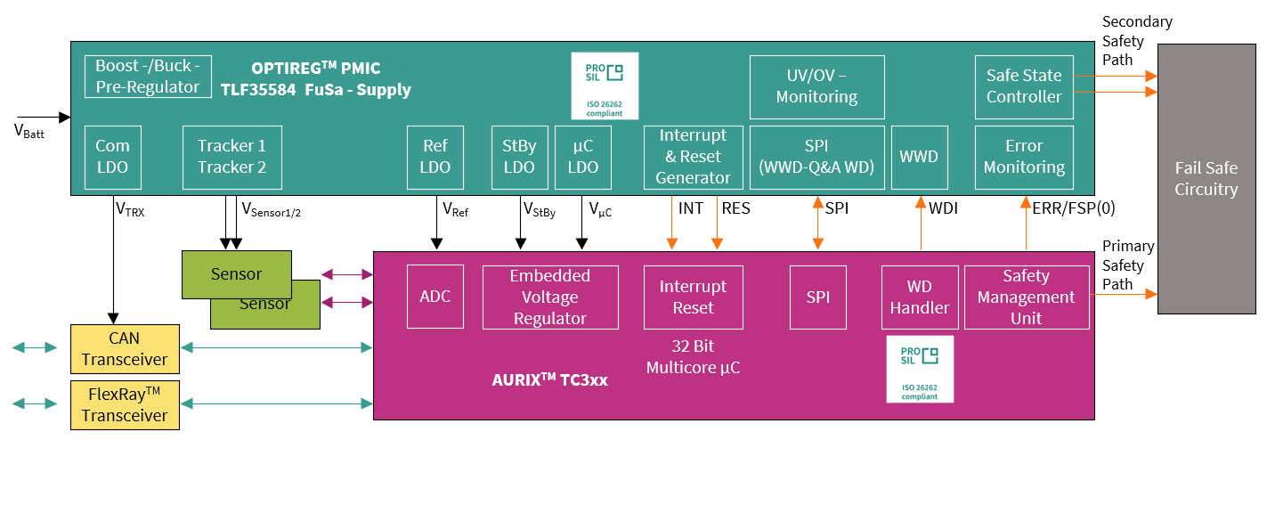
One of the primary roles of this device is to monitor the voltage supplies of the system, whether internally generated by the device or from other on-board regulators and, if necessary, disconnect the MCU from the power supply to avoid a violation of the safety goals.
The Infineon OPTIREG™ PMIC TLF35584 is capable of detecting dependent failures that affect both the function and the diagnostic, such as a watchdog error. When this happens, then the safety power supply can initiate a return to a safe state by driving output pins to disconnect the power feed to the actuators and/or triggering a reset of the MCU.
The safety power supply also monitors the fault signaling protocol (FSP) pin of the MCU that signals an internal failure, indicating that the MCU response is no longer reliable. In this case, the power supply is the ‘last man standing’ and its built-in safe state controller triggers a safe state to meet the safety goals for the system.
As the building blocks of a functional safety system are reviewed and understood, the benefits of sourcing from a single supplier both MCU and PMIC become immediately apparent. Each of the elements of the AURIX™ TC3xx system is specifically designed and tested to work alongside each other and contain signals and controls that significantly ease the task of building a system capable of reaching the highest safety integrity levels.
Safety path
The safety path is the signal chain and circuitry that enables and maintains the system’s safe state. For several applications, the safe state is achieved by disabling actuators, communication channels or the complete system.
In such systems, the safety path is therefore referred to as the safety shutdown path.
Primary safety path
The primary safety path is a safety path (shutdown path) that is managed directly by the safety microcontroller. The microcontroller can keep the application in a safe state if the assumptions of use are respected (for example, operating conditions in a valid range as described in the datasheet) and it is possible to act directly on motor-control signals, communication signals or other possible signals that activate a defined safe state of the system.
Secondary safety path
A secondary safety path is a safety (or safety shutdown) path established through the PMIC's safety functionality or other external hardware.
For example, the safe state of the system in
Figure 22
is intended to be achieved by the PMIC’s safe state outputs SS1 and SS2, which should be connected to system circuitry that can release and assert the safe state.
The secondary safety path will be implemented with a high degree of independence from the primary safety path of AURIX™ TC3xx to provide a redundant mechanism for cases in which the primary safety path is unreliable.
Figure 22. Example of primary and secondary safety paths for a communication block
Considerations on common-cause failures on pins and packages
In this section, the topic of common-cause failures (CCFs) in pins and packages will be addressed.
Based on the safety concept for TC3xx, a few functional blocks’ safety mechanisms require the use of two redundant channels (for example, ADC redundant channel acquisition):
Mission channel
Monitoring channel
Figure 23. Channel redundancy representation in the ADC functional block
Common-cause failures are the failure of two or more elements of an item resulting from a single specific event or root cause, which can affect both the mission and the monitor input/output (I/O) signals, potentially leading to failures.
Figure 24. Abstract representation of a common-cause failure
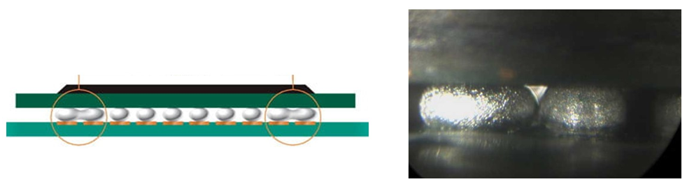
An example of a common-cause failure from the package perspective is when a BGA ball shorts its neighboring balls.
Figure 25. Illustrative example of a common-cause failure from the BGA ball level
shows how a common-cause failure can affect neighboring balls at the package level.
Figure 26. Common-cause failure example
The ball-out of packages LFBGA516 and LFBGA292 is separated into eight different groups. Those highlighted groups indicate that the balls from one group are appropriately separated from the balls from other non-adjacent groups.
The mission I/O pin can be used from one group and the monitor signal can be used from any other group, so that the mission and the monitor groups are not adjacent. This is valid not only for a generic I/O port but also for GTM and ADC modules’ pins when applying the redundancy principles.
As shown in
Figure 27
, if the mission signal is connected to the group highlighted in blue (group 1), then avoid connecting the monitor signal to the same blue group or to the adjacent group marked in yellow (group 2) and the group marked in purple (group 8).
Figure 27. TC399 LFBGA516 I/O configuration
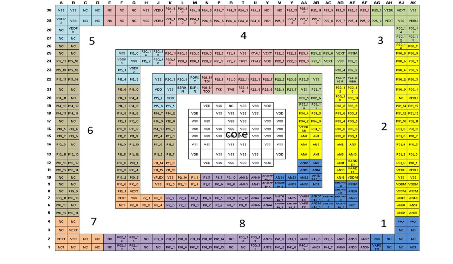
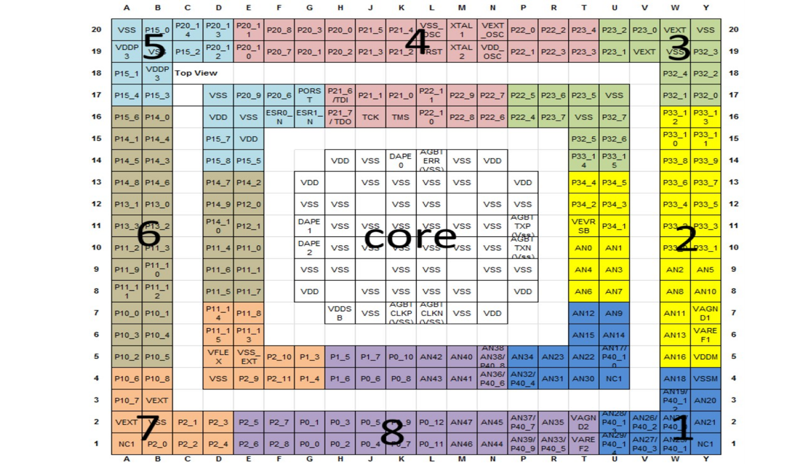
Figure 28. TC3971 LFBGA292 I/O configuration
AURIX™ TC3xx safety package for customers
To enable customers to reach the target safety level for their project, Infineon provides a comprehensive library file that contains all the functional safety documentation related to each specific TC3xx device and is required for the design of a safety-relevant system based on this specific microcontroller. This package is made available to customers under non-disclosure agreement for both ISO 26262 compliance and IEC 61508 compliance justification.
The "safety package" for ISO 26262 is composed of the documents as shown in
Table 2
.
Document | Description |
|---|---|
Safety case report | Serves as the work product requested by ISO 26262:2018 Part 2 Clause 6.5.4 and follows the guidance of ISO 26262, Part 10 Clause 5.3. |
Safety manual | Provides guidance for integrating the device into a safety system, assumptions of use, safety mechanisms and implementation hints. |
FMEDA template | Calculation tool to compute customized ISO 26262 random-fault-related metrics for TC3xx devices depending on the specific configuration for the customer application. |
Safety analysis summary report | Describes the performed safety analysis for the AURIX™ TC3xx devices and provides reference to the corresponding safety analysis results. |
Safety package release note | Present the set of customer-relevant safety documents, taken all together, to enable Infineon to substantiate the functional safety claims. Communicate to the integrator of the AURIX™ TC3xx device the major changes between the documents in this safety package and the documents referenced in the previous package. |
The subsequent sections provide more details about the concept related to metrics such as base failure rate, soft error rate and FMEDA.
Base failure rate (BFR)
The base failure rate (BFR) is the first input of the FMEDA. It is related to the hardware permanent errors only. Data commonly comes from the SN29500 or IEC TR 62380 standards. Infineon’s AURIX™ BFR template according to TR 62380 (or better ISO 26262-11:2018), provides the BFR for permanent faults (hard errors) for the die and the package separately.
The default mission profile is “Motor Control”, as it is the worst-case condition, and working and dormant times for the calculation of τ_i, τ_on + τ_off = 1 were considered. The integrators can change these values based on their own calculations for the mission profiles of the application.
Soft error rate (SER)
The soft error rate (SER) is related to hardware soft (non-permanent) errors and is composed of NSER and ASER data with a package-related adjustment factor, where:
NSER is a soft error rate caused by neutron radiation from cosmic rays at the earth's surface, obtained during accelerated neutron testing. The value depends on the altitude and the location on earth and is referenced to "New York Sea Level". The BFR related to SE caused by neutron radiation (NSER) is multiplied by the value entered in the related cell "Flux Factor for Neutron Particles". For scaling instructions, see JESD89 A.3
ASER is an alpha particle-originating soft error rate obtained during accelerated testing and caused by impurities of process and package materials, for example mainly because of mold compound, and is referenced to low alpha materials. It can also be caused by other materials, such as solder bumps. For bare die applications, the "Flux Factor for Alpha Particles" must be used to scale the SER with an appropriate scaling that considers the alpha activity of the material set for encapsulation and interconnect
As all AURIX™ TC3xx MCUs use low-alpha mold compound (alpha particle emission is 0.0010 cph/cm2) for the packages, the following equation for the SER is applied in the FMEDA.
The soft error rate is independent from the mission profile.
Failure modes, effects and diagnostic analysis (FMEDA)
Failure modes, effects and diagnostic analysis (FMEDA) is the analysis of the effect of random hardware faults on a safety requirement or safety goal, including the quantitative estimation of failure rates and the probability/rate of a safety goal violation.
Infineon provides support for an accurate estimation of the failure rate and diagnostic coverage of the AURIX™ TC3xx MCU, providing a FMEDA template that is fully configurable by the customer for their specific use case for both ISO 26262 and IEC 61508 standards.
Infineon FMEDA supply metrics for:
Permanent faults/hard errors (HE):
Random HW fault that occurs and stays (for example open, short and so on)
Transient HW faults/soft errors (SE):
Random HW fault that occurs once and subsequently disappears (for example bit-flip in SRAM because of alpha radiation)
Inputs for the FMEDA Excel sheet come from the BFR calculation and SER.
Figure 29. Infineon FMEDA template, inputs and outputs
References
Infineon Technologies AG:
AURIX™ TC3xx User's Manual
V2.0.0, 81726 Munich, 2021-02
TriCore™ TC1.6.2 core architecture manual
ISO 26262:2018 Road vehicles- Functional safety
IEC 61508:2010 Functional safety of electrical/electronic/programmable electronic safety-related systems
AN1000 - FuSa in a Nutshell - release note
AN1200 - FuSa in a Nutshell - Safety software enablement with AURIX™
Glossary
Definition | Description | Notes |
|---|---|---|
ASC | Active Short Circuit | in the Inverter Use Case |
Architectural Element | The smallest element on which the FMEDA is performed | |
ASIL | Automotive Safety Integrity Level; refer to ISO 26262-1:2018, 3.6 | |
BEV | Battery-powered Electric Vehicle | |
CCF | Common-Cause Failure; refer to ISO 26262-1:2018, 3.18 | |
DC | Diagnostic Coverage; refer to ISO 26262-1:2018, 3.33 | |
DFA | Dependent Failure Analysis identifies single events that can cause multiple sub-parts to malfunction (for example, intended function and its safety mechanism) and lead to a violation of a safety requirement or safety goal. | |
DMI | Data Memory Interface | |
DPF | Dual-Point Failure; for the definition refer to ISO 26262-1:2018, clause 3.38 | |
DSPR | Data Scratch Pad RAM | |
ECU | Electronic Control Unit | |
FHTI | Fault Handling Time Interval is defined in ISO 26262 as the sum of three elements: The fault detection time, the fault reaction time and the time for the system to reach a safe state. | |
FTTI | Fault Tolerant Time Interval; for the definition refer to ISO 26262-1:2018, clause 3.61 | |
FMEA | Failure Mode and Effects Analysis | |
FMEDA | Failure Modes, Effects and Diagnostic Analysis Analysis of the effect of random hardware faults on a safety requirement or safety goal, including quantitative estimation of failure rates and the probability/rate of a safety goal violation | Quantitative Bottom-up HW only |
FTA | Fault Tree Analysis Analysis in which a top-level failure mode is broken down to a combination of lower-level faults (root causes) using a Boolean logic approach | Qualitative (may be quantitative) Top-down HW only |
HARA | Hazard Analysis and Risk Assessment; Refer to ISO 26262-1:2018, 3.76 | |
HW | Hardware | |
IC | Integrated Circuit | |
IEC | International Electrotechnical Commission | |
ISO | International Organization for Standardization | |
LBIST | Logic Built-in Self Test | |
LMU | Local Bus Memory Unit | |
MCU | Microcontroller unit | |
MMIC | Monolithic Microwave Integrated Circuit is a type of integrated circuit (IC) device that operates at microwave frequencies (300 MHz to 300 GHz). These devices typically perform functions such as microwave mixing, power amplification, low-noise amplification and high-frequency switching. | |
PMI | Program Memory Interface | |
PMIC | Power Management ICs (PMICs) | |
PMSM | Permanent Magnet Synchronous Machine (with rare earth material) | Motor type |
PSPR | Program Scratch Pad RAM | |
Safety Flip Flops (SFF’s) | Safety flip-flops are special flip-flops that implement a hardware mechanism capable of detecting bit flips within the protected registers, thus preventing single-point faults. | |
Safety Measure | Activity or technical solution to prevent, detect, control or mitigate systematic and random failures. | |
SBC | system basis chips (SBC) SBCs combine mainly three functionalities in a single device: Power supply, CAN and/or LIN transceivers and supporting features (MCU supervision, SPI interface and so on). This integration makes SBC a potentially better alternative to standalone (discrete) solutions, especially in terms of total solution cost and total area. | |
SE | Soft Error | |
SM | Safety Mechanism: for the definition refer to ISO 26262-1:2018, 3.142 | |
SW | Software | |
SPU | Signal Processing Unit | |
STP | Shoot-Through Protection: Protection typical of an inverter gate driver so that the high side and the low side of the three-phase motor legs cannot be activated simultaneously | |
VCU | Vehicle Control Unit |
Revision history
Document revision | Date | Description of changes |
|---|---|---|
V1.0 | 2024-06-28 | Initial release |
V1.1 | 2025-05-28 | Template update; no content update |