AP32376 eMotor Drive Kit for the AURIX™ product family
32-bit TriCore™ AURIX™ microcontrollers
About this document
Scope and purpose
This application note gives an overview of how to spin a Permanent Magnetic Synchronous Motor (PMSM) with Field Oriented Control (FOC), and also provides a brief introduction to the hardware of the eMotor Drive Kit.
The Generic Timer Module (GTM) generates the PWM, the VADC measures the phase current, and the DSADC or GPT12 determines the motor position. These modules are available in the AURIX™ family of TriCore™ products from Infineon. Thanks to the high performance of the TriCore™ microcontroller and its GTM, the generation of PWM´s to control a B6 bridge, both types of ADC, and the implementation of further algorithms such as Field Oriented Control, needs less CPU load.
Intended audience
This document assumes that readers have access to the TriCore™ Architecture Manuals and have at least some general knowledge of the TriCore™ instruction set, architectural features, and peripheral modules.
Introduction
In the automotive arena, multi-phase motors are increasingly replacing brushed motors. For example, Permanent Magnetic Synchronous Motors (PMSM) are used in hydraulic pumps, for assisting steering systems, and in transmission systems. In the past many applications were addressed with DC motors, but today automotive suppliers would like to use PMSM motors to achieve greater robustness and efficiency.
For most of these applications FOC (Field Oriented Control) is a favored method. The eMotor Drive Kit supports this method.
With the eMotor Drive Kit it allows to drive a 3 Phase brushless motor. Applications can be developed easily. The eMotor Drive Kit is equipped with a variety of interfaces for position detection and current measurement. Additionally a driver IC (TLE 9180) and a complete B6 bridge allow spinning a motor up to 50 Watt.
Thanks to the Application Kit and the connectors it is easy to develop TriCore™ based applications with the corresponding tools. Subsequently the applications can be downloaded and tested.
For detailed technical information about TriCore™ based products (TC2xx and TC3xx for example) please refer to the corresponding User Manual of the devices.
Hardware
The eMotor Drive Kit has the following features:
- Fits to all Application Kits
- Drives a 3 Phase PMSM / BLDC (12 Volt / 50 Watt)
- Sensing of Motor Position with Resolver/Encoder/Hall
- Phase Current Measurement with up to 3 Shunts in Ground Path
- Configuration / Diagnostic of the TLE 9180 via SPI
Motor Position Sensor
The hardware can be used with a resolver, encoder, or with hall sensors.
Resolver
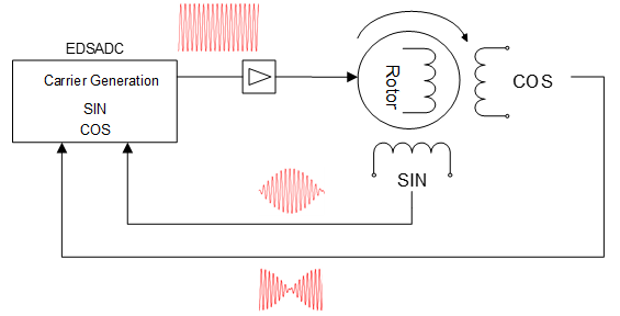
Assembled with a resolver the carrier signal for the excitation coil is generated by the carrier generator of the Delta-Sigma Analog Converter. Both received return signals are evaluated in the Delta-Sigma Analog Converter.
Actions include removing the carrier, delay compensation, and filtering.
Position calculation is made by the CPU.
Encoder

Mounted with an encoder, the motor delivers three signals. Two of them provide a square wave signal with a 90 degree phase shift. The third one generates once per revolution a short pulse for synchronization. To increase the robustness of the system for long distances, a line driver circuit is recommended. The GPT12 peripheral is ideal for evaluating the motor position.
Hall sensors

Using Hall sensors at least each 60 degrees, an edge is generated. The SPEx of the GTM can be used to process the Hall signals.
PWM
PWM generation is done with the GTM. If the Dead Time Module is not available, seven timers are required.
- Channel 0 works as master timer, resets all CN0, and updates the CM0 and CM1 of all corresponding timers.
- Channels 1 to 6 are assigned to the low-side / high-side switches of the B6 power bridge.

If the Dead Time Module is used, three channels are required.
- Channels 0 to 2 are assigned to the low-side / high-side switches of the B6 power bridge.
- Channel 0 works as master timer. At CM0 count direction is changed and all SRs are updated.
- Update of SR0 can happen at begin and end of each PWM.
- Dead-time can be individually configured for each PWM.

Current sensing
Current sensing is implemented with three shunts in the low path of the B6 ridge. Typically two currents are measured. The third one is calculated. The current measurement needs to be done when the low-side switches are closed. Therefore the triggers become active in the middle of the PWM signal. The trigger is released with an additional timer channel 7.
- If no Dead Time Module is available, 8 channels are allocated to handle PWM generation and current measurement.
- If a Dead Time Module is used the number of needed channels are reduced to four.


FOC
Field Oriented Control or vector control is a math technique for controlling brushless DC and AC induction. It consists of two types of transformations and the use of a Proportional-Integral controller.

Clarke transformation
The Clarke transformation converts the three phase current into an easier to handle, 2 components current. Conversion is from a, b, c Frame into α, β Frame. The α and β components are phase shifted by 90°.

Park transformation
The park transformation allows direct access to the rotation of the rotor. The output of the calculation are direct currents split in to Iq and Id.
- Iq is the torque given current.
- Id is the magnetization current.
The vectors need to be transformed back, and thanks to space vector modulation the GTM module generates the corresponding PWM signals.
For synchronous machines only the Iq component needs to be controlled with a PI controller.
The Id component is controlled to zero.
Inputs for this calculation are α, β Frame and the rotor position (φ).

For Interior Permanent Magnet (IPM) motor voltage, de-coupling allows driving the motor more efficiently. It is not implemented.
For Field weakening the Id component can be influenced, so it is possible to drive the motor faster at the nominal speed.
Space Vector Modulation
Space Vector Modulation (SVM) is used to generate a three phase sinusoidal PWM signal, to drive the power switches.
The three phased inverter is made of three half-bridges with a total of 6 switches:

The state of the inverter is defined by vector[CBA].
- C represents the state of the high-side switch c with 0 for opened and 1 for closed.
- B represents the state of the high-side switch b.
- A represents the state of the high-side switch a.
We obtain the following 8 possible vectors:
For the vectors [000] and [111] the stator is in short circuit. These vectors are called ZERO vectors.
All other vectors produce a space vector equal to:
Where:
k = [1..6]
The vectors can be represented in the (α,β) stationary reference frame and define 6 areas named "sectors" (sector 1 to sector 6):
Any space vector voltage Vabc
can be represented as the weighted average of two adjacent space vectors and the vector ZERO:

The space vector algorithm produces the following phase potentials:
And the following line to line voltages:
Continuous and discontinuous SVM
Figure 14. Continuous versus discontinuous area

The range available for the continuous Space Vector Modulation is represented by the circle inside the hexagon in the figure, and corresponds to a modulation index of 0.906% (), because the output voltage is limited by the DC-link voltage.
The total hexagon area can still be used for saturated SVM, but introduces more harmonics.
In the continuous domain, the maximum fundamental phase voltage that can be produced by the inverter for a given DC link voltage is:
eMotor Drive Kit
The chapter provides a short description of the eMotor Drive Kit board.
Features
- Driving of a 3 Phase PMSM / BLDC (12Volt / max.50 Watt)
- Sensing of Motor Position with Resolver, Encoder or Hall Sensors
- Phase Current Measurement with DC Link Shunt
- Phase Current Measurement with 2 / 3 Shunts in Ground Path
- Configuration / Diagnostic via SPI
- eMotor Drive Kit fits perfectly to Application Kit TC2xx, TC3xx
- Low Power Status LED
- Dimension: 100mm x 120mm
Connectors
The eMotor Drive Kit offers a wide variety of Connectors:
- 4 mm Multicomp A2.107 for 12 Power Supply
- 4 mm Multicomp A2.107 for Motor Connection
- Phoenix Contact PTSA 0,5/6-2,5-Z for Resolver
- Phoenix Contact PTSA 0,5/6-2,5-Z for Hall Sensors
- Phoenix Contact PTSA 0,5/8-2,5-Z for Encoder
- General purpose 10-Pin plug connector for Encoder
- Two 40-Pin Connectors with I/O Signals
Components
- Infineon´s Next Generation Bridge Driver TLE 9180
- Dual N-Channel MOSFETs IBG20N04S4-08A
- Low Dropout Linear Voltage Regulator TLE42744
- NPN/PNP Silicon AF Transistor Array BC847PN
- Rail To Rail Quad CMOS Operational Amplifier With Shut Down LMV344ID
- Single Supply, General Purpose Dual Operational Amplifier OPA2171A
- Quadruple RS-485 Differential Line Receiver SN65LBC175A
- LED to validate Power Supply (5Volt)
Block Diagram
Figure 15. eMotor Drive Kit Block Schematic

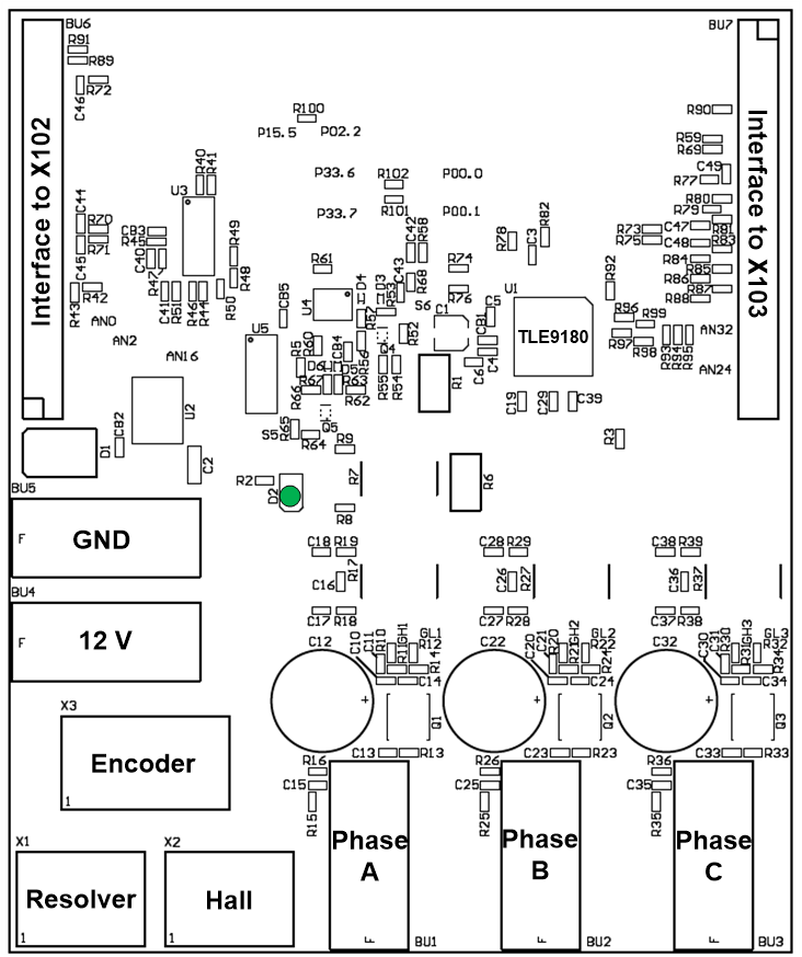
Placement
Figure 16. eMotor Drive Kit Top Placement
eMotor Drive Kit board
The eMotor Drive Kit follows a daughter board approach. It has to be used with one of the Application Kit´s via the connectors BU6 and BU7, see Figure 17. The power supply of the eMotor Drive Kit supplies the Application Kit.
Connectors
The eMotor Drive Kit provides connectors for one 3 Phase motor, several sensor types and power supply.
Power Supply
The 3 Phase Bridge Driver IC needs 2 different supply voltages. The 12 V are supplied externally. The 5V are generated internally via the Infineon TLE 42744 DV50.
The LED (+5V) indicates the status of the 5V voltage.
The Board has to be connected to an external 12V DC power supply via BU4 (12V) and BU5 (GND).
The maximum power consumption is not specified but the current should not exceed 3 A.
Motor
The eMotor Drive Kit supports the control of a 3 phase permanent magnetic synchronous motor. Three general purpose connectors (Black, red, yellow) need to be connected with the motor.
Resolver
The eMotor Drive Kit supports Resolver interface. Thanks to the DSADC no external resolver IC is needed. The pinout for the resolver connector is shown in Figure 18. The TC23x does not offer the DSADC. The position evaluation can be realized with the VADC.
Encoder
The eMotor Drive Kit supports Encoder interface. Via a differential line receiver the encoder is connected with GPT12_T3 module. The pinout for the encoder connector is shown in Figure 19.
Hall
The eMotor Drive Kit supports Hall Sensor interface. The three hall sensor signals are connected with Sensor Pattern Evaluation (SPEx) module of the GTM module. The pinout for the Hall connector is shown in Figure 20.
Motor Control
The hardware of the eMotor Drive Kit has been designed to support the field oriented control of a PMSM motor. The motor position and the phase current need to be known to apply the right PWM pattern.
PWM Pattern
Normally the motor is controlled via space vector modulation. Six independent PWM are generated with the GTM. The update of the PWM pattern occurs periodically.
Current Control
The current can be measured based on the application. At least one shunt is required in the DC Link. A more advanced method is to measure the current in each phase. By default the eMotor Drive Kit uses this method.
Up to 3 integrated amplifiers in the TLE 9180 support the current measurement. The outputs of the amplifiers are connected with 3 independent ADC channels. Depending of the Application Kit used, the phase current is measured with different channels. For detailed information see eMotor Drive Kit board.
The trigger for the ADC channels can be realized with the same Timer module as the PWM´s are generated.
Position Sensing
Depending on the application, Hall sensors, the encoder, or the resolver are mainly used.
Hall sensor signals are directly connected with the SPE module. It can be used to evaluate three Hall sensor inputs.
The Microcontroller evaluates the Hall sensor signals, connected to TINx inputs. With a simple state machine the motor position can be evaluated. For detailed information see Signal description.
The carrier for the primary coil of the resolver is generated with the internal carrier generator. For driving the coil an external circuit is on the board. The secondary coils are connected via external circuit with the DSADC. The COS signal and the SIN signal are processed via external OPAMP and connected to DSADC. The processing of the signals and the calculation of the motor position is done internally with software.
The encoder signals are connected to a differential line receiver on board. The outputs are connected to the GPT12 module.
- Enc A is connected to T3INA.
- Enc B is connected to T3EUDA.
- The Top zero is connected to T4INA
- reset always the internal counter
3 Phase Bridge Driver TLE9180
The TLE9180 is an advanced gate driver IC dedicated to control 6 external N-channel MOSFETs forming an inverter for high current 3 phase motor drives application in the automotive sector.
Overview
An advanced high voltage technology allows the TLE9180 to support applications for single and mixed battery systems with battery voltages of 12V, 24V and 48V even within tough automotive environments in combination with high motor currents. Therefore bridge, motor and supply related pins can withstand voltages of up to 90V. Motor related pins can even withstand negative voltage transients down to -7..-15V without destruction.
All low- and high-side output stages are based on a floating concept and its driver strength allows it to drive the lowest RDSON MOSFETs.
An integrated SPI interface is used to configure the TLE9180 for the application after power-up. After successful power-up, parameters can be adjusted by SPI, and monitoring data, configuration and error registers can be read. Cyclic redundancy check over data and address bits ensures safe communication and data integrity.
GND related bridge currents can be measured with up to 3 integrated current sense amplifiers. The outputs of the current sense amplifiers support 5V ADCs and the robust inputs can withstand negative transients down to -10V without destruction. Low Noise, low settling times and high accuracy are the main features of the integrated current sense amplifiers. Gain and the zero current voltage offset can be adjusted by SPI. The offset can be calibrated.
Diagnostic coverage and redundancy have increased steadily in recent years in automotive drive applications. Therefore the TLE9180 offers a wide range of diagnostic features, such as monitoring of power supply voltages and system parameters. A testability of safety relevant supervision functions has been integrated. The failure behavior, the threshold voltages and the filter times of the supervisions of the device are adjustable via SPI.
The TLE9180 is integrated
- in a VQFN48 7*7 package with an exposed pad
- in a LQFP64 package with an exposed pad
Due to its exposed pad the gate driver IC provides an excellent thermal characteristic.
OptiMOS Power Transistor
For the B6 bridges, three dual N.channel MOSFET IPG20N04S4-08A in a smart PG-TDSON-8-10 package are selected.
Signal description
For more information about the signals please take a look in the documentation of the selected TC2xx/TC3xx devices, the datasheet of the TLE 9180, and/or the schematics of the board.
| Short name | Description | Pin number |
|---|---|---|
VCC_IN | Supply Input TriBoard( 5,5V...50V) | 1 |
VEXTA | nc. | 2 |
GND | Ground | 3 |
GND | Ground | 4 |
CH2NA | Analog input / Resolver VCC/2 | 5 |
CH2PA | Analog input / Resolver SIN | 6 |
CH0NA | Analog input / Resolver VCC/2 | 9 |
CH0PA | Analog input / Resolver COS | 10 |
VRO | Analog input / Reference Voltage | 11 |
VO1 | Analog input / Phase current 1 | 12 |
PFB1_Enable | Enable PFB1 | 17 |
PFB1 | Phase Feedback | 13 |
PFB2 | Phase Feedback | 18 |
PFB3 | Phase Feedback | 20 |
MOSI | QSPI | 27 |
MISO | QSPI | 28 |
CSN | QSPI | 29 |
CLK_SPI | QSPI | 30 |
/ERR | Error | 33 |
/SOFF | Independent Save State | 37 |
/ENA | Enable | 38 |
| Short name | Description | Pin number |
|---|---|---|
VCC_IN | Supply Input TriBoard( 5,5V...50V) | 1 |
VEXTB | nc. | 2 |
GND | Ground | 3 |
GND | Ground | 4 |
/INH | Inhibit (active low) | 10 |
CGPWM_N | Primary Coil | 13 |
CGPWM_P | Primary Coil | 14 |
HALLA | HALL A | 16 |
HALLB | HALL B | 17 |
HALLC | HALL C | 18 |
ENC_A | Encoder A | 19 |
ENC_B | Encoder B | 20 |
ENC_Z | Encoder Top Zero | 21 |
IL1 | PWM Lowside 1 | 24 |
/IH1 | PWM Highside 1 | 25 |
IL2 | PWM Lowside 2 | 26 |
/IH2 | PWM Highside 2 | 27 |
IL3 | PWM Lowside 3 | 28 |
/IH3 | PWM Highside 3 | 29 |
VO3 | Analog input / Phase current 3 | 38 |
VO2 | Analog input / Phase current 3 | 40 |
| Short name | Description |
|---|---|
S1 | Secondary coil SIN |
S2 | Secondary coil SIN |
S3 | Secondary coil COS |
S4 | Secondary coil COS |
S5 | Primary Coil |
S6 | Primary Coil |
| Short name | Description |
|---|---|
HALLA | Hall Sensor A |
HALLB | Hall Sensor B |
HALLC | Hall Sensor C |
| Short name | Description |
|---|---|
ENC_CH_A | Incremental Signal Channel A |
ENC_CH_AN | Neg. Incremental Signal Channel A |
ENC_CH_B | Incremental Signal Channel B |
ENC_CH_BN | Neg. Incremental Signal Channel B |
ENC_CH_Z | Incremental Signal Channel Z |
ENC_CH_ZN | Neg. Incremental Signal Channel Z |
| Short name | Description |
|---|---|
APC | Activation of phase cut off FETs |
/ERR | Error signal (active low) |
IH1 | Input for high-side switch 1 (active low) |
IL1 | Input for low-side switch 1 (active high) |
IL2 | Input for low-side switch 2 (active high) |
IH2 | Input for high-side switch 2(active low) |
IH3 | Input for high-side switch 3 (active low) |
IL3 | Input for low-side switch 3 (active high) |
MISO | SPI Master In, Slave Out |
MOSI | SPI Master Out, Slave In |
CSN | SPI Chip Select |
CLK_SPI | SPI clock input |
VCC | Power supply for digital I/O pins and input for VCC monitoring |
SOFF | Independent safe state switch off (active low) |
VDH | Connection to drain of high-side switches for short circuit detection; Supply for CP2 |
CH2 | + Terminal for pump capacitor of charge pump 2 |
CL2 | - Terminal for pump capacitor of charge pump 2 |
INH | Inhibit pin (active low) |
VS | Voltage supply |
CH1 | + Terminal for pump capacitor of charge pump 1 |
CL1 | - Terminal for pump capacitor of charge pump 1 |
CP_GND | Charge pump GND |
CB | Buffer capacitor for charge pump 1 |
GL1 | Output to gate low-side switch 1 |
SL1 | Connection to source low-side switch 1 |
BH1 | Bootstrap pin for + terminal of bootstrap capacitor CBS1 |
SH1 | Connection to source high-side switch 1 |
GH1 | Output to gate high-side switch 1 |
SL2 | Connection to source low-side switch 2 |
GL2 | Output to gate low-side switch 2 |
BH2 | Bootstrap pin for + terminal of bootstrap capacitor CBS2 |
SH2 | Connection to source high-side switch 2 |
GH2 | Output to gate high-side switch 2 |
BH3 | Bootstrap pin for + terminal of bootstrap capacitor CBS3 |
SH3 | Connection to source high-side switch 3 |
GH3 | Output to gate high-side switch 3 |
SL3 | Connection to source low-side switch 3 |
GL3 | Output to gate low-side switch 3 |
GND | GND |
PFB3 | Phase feedback of motor connection phase 3 |
PFB2 | Phase feedback of motor connection phase 2 |
PFB1 | Phase feedback of motor connection phase 1 |
VRO | Output of reference voltage of differential amplifier |
VO3 | Output of differential 3 amplifier for shunt signal amplification |
VO2 | Output of differential 2 amplifier for shunt signal amplification |
VO1 | Output of differential 1 amplifier for shunt signal amplification |
ISP | + Input of differential amplifier for shunt signal amplification |
ISN | - Input of differential amplifier for shunt signal amplification |
AGND | Analog ground especially for the current sense differential amplifier |
ENA | Enable pin (active high) |
Connector Pin assignment
Figure 17. eMotor Drive kit Top Placement

Resolver connector pin out
Figure 18. Resolver connector pin out

Encoder connector pin out
Figure 19. Encoder connector pin out

Hall connector pin out
Figure 20. Hall connector pin out

Schematics and Layout
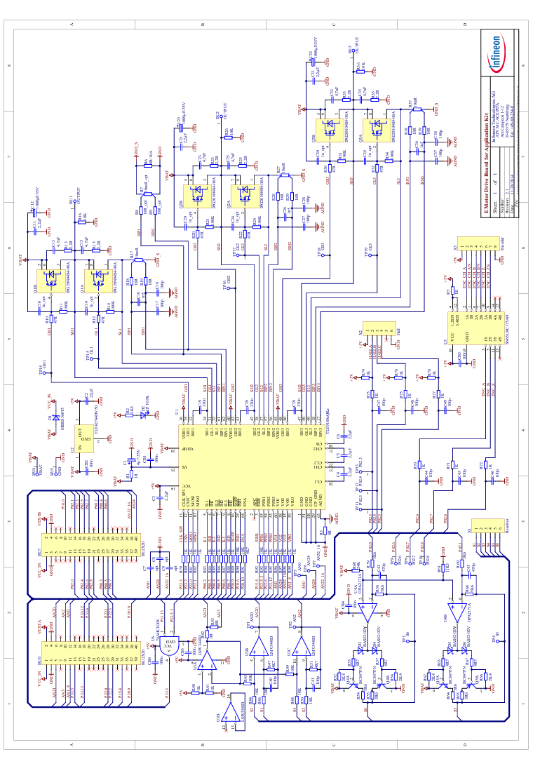
Schematic
Figure 21. Schematic
Layout
Figure 22. Layout Plot Top Layer

Figure 23. Layout Plot Bottom Layer

References
- AURIX™ User´s Manual TC21x/TC22x/TC23x Family, V1.1 2014-12
- AURIX™ User´s Manual TC27x C-Step, V2.2 2014-12
- Application Kit Manual TC2X4 V1.0
- Application Kit Manual TC3X7 V2.0
- Application Note AP32298
- Datasheet TLE9180D-31QK Rev. 1.0
- Nanotec Datasheet Brushless DC Motor DB42S02
Revision history
| Document revision | Date | Description of changes |
|---|---|---|
V1.0 | September 2018 | First release |
V1.1 | 2024-04-17 | Template update; no content update. |