AP32381 AURIX™ TC3xx startup and initialisation
32-bit microcontrollers
About this document
Scope and purpose
This document describes the initialization sequence of AURIX™ TC3xx microcontrollers, and gives recommendations with regards to configuration, including Boot Firmware configuration, and user start-up software implementations.
The Infineon AURIX™ automotive microcontrollers are feature-rich to fulfill the requirements of safety critical applications. Start-up activities include:
- On powering-up the microcontroller it goes through a brief power-up sequence and comes out of reset state.
- Boot Firmware is the first instruction sequence executed immediately after reset. This prepares the hardware for the generic application needs of the targeted domain where the controller is being used. The execution control is then passed to the application start-up software.
- Application start-up software further initializes the hardware and software for the specific application.
- Execution and control is handed over to the application.

Intended audience
This document is intended to enable designers to understand the start-up sequence and to implement features in their specific applications.
Acronyms and definitions
| ABM | Alternate Boot Mode |
| BIV / BTV | Base Interrupt Vector table / Base Trap Vector table |
| BMHD | Boot Mode Header |
| BMI | Boot Mode Index stored in BMHD locations |
| BROM | Boot ROM |
Cold PORST Cold reset | Cold Power On Reset means that a supply ramp-up or supply fail on any supply rail (1.25V, 3.3V or 5V) had taken place. RAM memories uninitialized |
| CSA | Context Save Area |
| ECC / CRC | Error Correction Code / Cyclic Redundancy Check |
| ED | Emulation Device |
ESR0 pin | External Service Request 0 pin. ESR0 is the default hardware reset output pin. The reset output pin may be de-asserted after a configurable delay after reset. |
| ESR1 pin | External Service Request 1 pin. ESR1 pin serves as default Non-Maskable Interrupt (NMI) pin which in turn triggers a Class 7 CPU trap. |
| EVR | Embedded Voltage regulator. EVRC generates 1.25 V. EVR33 generates 3.3 V |
| HWCFG | Hardware Configuration pins |
| ISP | Interrupt Stack Pointer |
| LDO | Linear Drop Out regulator topology |
| MTU / MBIST | Memory Test Unit / Memory Built In Self Tests |
| EMEM | Extension Memory |
| ED | Emulation Device |
| PSPR / DSPR | Program Scratch Pad RAM / Data Scratch Pad RAM |
| PSW | Program Status Word register |
| SCU | System Control Unit |
| SMPS | Switch Mode Power Supply regulator topology |
| STADD | User Start-up Address after firmware execution configured in ABM/BMI header. STADD represents a flash configurable reset vector address where the first instruction of the user code is located. |
| UCB | User Configuration Block in Flash |
| Warm reset | Warm reset may be caused by a PORST assertion, application or system reset trigger. A warm reset is a reset where there was no supply fail. Consistency of RAM content is ensured (i.e. the values are retained). |
Reset and analog power-up
The start-up sequence is triggered by different reset events. Based on the previous reset triggering event, the appropriate start-up sequence is executed.
Events triggering the start-up process
Cold (initial) power-on
This is the reset event caused by the initial powering-up of the microcontroller device, and results in initialization of the entire microcontroller system.
System reset
This is the reset event caused by multiple reset sources, called when the microcontroller device is powered-on. This reset event can be requested by different sources such as internal signals (hardware/software) or external hardware signals.
Application reset
This is the reset event caused by multiple reset sources and occurs while the microcontroller device is powered on. This reset event can be requested by internal signals (hardware/software) or external hardware signals for example.
This reset leads to an initialization of all the peripherals, the CPUs, and parts of the SCU.
CPU module reset
This is the reset event for individual TriCore™ CPUs which sends them in to halt status.
In the case of a CPU0 module reset, the execution jumps to the application start.
This reset only initialises the affected CPU. Other system elements outside the impacted CPU(s) are not affected.
Analog power-up
On-chip linear and switch mode voltage regulators are implemented in the AURIX™ TC3xx thereby enabling a single source power supply concept. The external nominal system supply from the external regulator may be either 5 V or 3.3 V. The Embedded Voltage Regulators (EVR33 and EVRC) generate the VDDP3 and VDD supply voltages required internally for the core and flash domains.
All supply voltages are monitored for brown-out conditions by primary monitors setting the device into cold power-on reset state in case of violation.
All supply and generated voltages are monitored redundantly by secondary monitors against programmable over-voltage and under-voltage levels. If these levels are violated either an interrupt or an alarm to the SMU is generated.
The choice of the supply scheme at start-up is based on the latched status of HWCFG [2:1] before PORST release and is indicated by PMS_PMSWSTAT.HWCFGEVR status flags.
HWCFG [2:1] are latched during supply ramp-up and the respective regulators are consequently started. The latched values are stored in PMSWSTAT.HWCFGEVR register bits.
The latched values are retained through a cold PORST and only reset in case of EVR LVD (Low Voltage Detector) reset.
HWCFG signals are filtered through a spike / glitch filter and are monitored for a constant level over a 60µs nominal de-bouncing period before the value is considered as valid so as to ensure reliable operation in noisy environment.
A built-in power self-test (PBIST) at start-up allows for testing critical power functions and primary monitor diagnostics. VEVRSB and VEXT voltages are evaluated using a secondary monitor ADC during PBIST before the start of internal EVRs.
The internal EVR Pre-Regulator (EVRPR) voltage based on the Primary Low Power Bandgap (PLPBG) for internal pre-regulator (VDDPD) generation is tested using the secondary monitor ADC against Secondary Bandgap (SHPBG) during the PBIST.
The POR bandgap based VDDPD detector monitors the Primary Low Power Bandgap (PLPBG) for under-voltage violation.
After regulator start-up the power rails, VEXT, and VDDP3, are checked for limits:
- Power rails = 5,84V / 2,75V ± 5%
- VEXT = 5,84V / 2,75V ± 5%
- VDDP3 = 3,81V / 2,0V ± 5%
- VDD = 1,46V / 1,0V ± 5%
Cold Reset is de-asserted on successful test completion.

Boot Firmware
Boot Firmware is stored in BOOT ROM. This is first code to be executed by the CPU after start-up.
For AURIX™ TC3xx microcontrollers, Boot Firmware is executed by CPU0. During start-up other CPUs in the system are in Halt state until they are explicitly started.
The Boot Firmware is programmed in BROM during production. This code is entered after a supply ramp-up upon PORST pin reset assertion, System reset, an Application reset, or CPU0 kernel reset. Based on reset type and user configuration, the Boot Firmware executes different start-up sequences.
Boot Firmware contains procedures to initialize the device depending on one or more from the following:
- Configuration of several UCBs
- HWCFG[5:3] pins
- The type of reset event which has triggered the start-up execution
Steps involved in Boot Firmware
These steps give brief overview of Firmware functionality.
- Start Flash ramp-up
- Flash is started and brought to a state where all the operations (read, erase, program, and command sequences) can be performed within the full range of specified working conditions.
- RAM initialization
The RAM initialization procedure fills selected RAM areas with zeroes. ECC values are automatically initialised. RAM initialisation behaviour can be configured in UCB with the following options:
- Enable or disable RAM initialization on cold or warm power-on reset, by configuring the RAMIN bitfield in the PROCONRAM register. By default this field is set for RAM initialisation for power-on reset.
- Enable or disable RAM initialization for each of the CPU specific RAMs, by configuring the RAMINSEL bitfield in the PROCONRAM register. By default this field is set for all the CPUs.
- Enable or disable RAM initialization for LMU and AMU RAM areas by configuring the LMUINSEL bitfield in the PROCONRAM register. By default this field is set for all the LMUs.
- Select and execute start-up modes
Evaluate the Boot Mode Headers (BMHDx, x=0...3). If evaluation results in valid BMHD, the selected mode is taken, either directly from the value configured in BMHD or according to the state at HWCFG [5:3] pins, if pin-configuration is enabled in BMHD. Otherwise it will check for other boot modes. Possible cases are listed here in case no valid BMHD is found.
- If no valid BMHD found and both HSM boot and Boot Mode lock are
disabled
It is considered that there is no user code available which needs to be started. Check if Halt After Reset request has been received.
- If yes, install BOOT_CFG to Internal start from Flash mode
- If not, install BOOT_CFG to Generic BSL mode; install the first address of CPU0 Program scratchpad RAM (CPU0_PSPR) as user code start address into BOOT_ADDR.
- If no valid BMHD found and either HSM boot or Boot Mode lock is
enabled
In this case SSW cannot select any start-up mode, which means that no exit from SSW will be taken. In such a case Boot Firmware will check if there is debug access. If debug access is enabled, SSW enables the debug interface and an endless NOP loop will be entered.
- If no valid BMHD found and both HSM boot and Boot Mode lock are
disabled
- Boot with HSM enabled
- The Hardware Security Module (HSM) CPU is a 32-bit CPU based on the ARM instruction set. All mandatory BOS functions for internal testing, production use, and start-up behaviour, are stored in the boot ROM of the HSM.
- The Boot Firmware boots the HSM module (i.e. HSM executes its firmware) when the field DMU_SP_PROCONHSMCFG.HSMBOOTEN is set. Depending on the value in PROCONHSMCFG.SSWWAIT the Boot Firmware waits for acknowledgement from the HSM before releasing the jump of CPU0 to user code.
- HSM can lock the debug interface (enforce “communication mode”). The main CPUs can also lock the debug interface. The main CPUs can release only their lock but not a lock imposed by the HSM. The HSM can always unlock the debug interface.
- Lockstep Configuration
Boot Firmware configures Lockstep. If a valid BMI has been found during start-up mode evaluation, lockstep control for CPUs supporting lockstep is installed from the BMI.LSENAn bits into the respective LSENn bits of SCU_LCLCON0/1 registers (n=0,1,2,3). Otherwise lockstep for CPU0 is disabled by clearing SCU_LCLCON0.LSEN0.
- Debug System handling
The Boot Firmware unlocks the Debug Interface if debug access to the device is enabled.
If debug access is enabled, Halt After Reset (HAR), which is to break the execution before the first user code instruction, will be performed, if requested from an external tool.
The Boot Firmware will terminate immediately (which means that the device does not boot), if:
- an error occurs during Flash ramp-up
- the Flash Config sector is corrupted (unrecoverable data error)
- any of the User Configuration Blocks (UCBs) evaluated by Boot Firmware are in ‘error’ state or contain unrecoverable data errors
Start-up configuration (Boot options)
Start-up configuration in AURIX™ devices can be selected by:
Configuration by Boot Mode Index (BMI)
- According to values taken from dedicated locations in Flash
- The user code Start Address (STADD) is configurable in the Boot Mode Header (BMHDx.STAD) data structure.
Hardware configuration
- only if enabled in BMI and the HWCFG[3] pin is tied low
- according to the values at configuration pins
Boot Mode Header
The Boot Mode Header data structure is referenced by the Boot Firmware to configure the start-up behaviour.
In the AURIX™ TC3xx family of products, four sets of Boot Mode Headers (BMHDx for x=0- 3) are defined in UCB. To detect the data corruption, each of these data structure is replicated with its copy. Each set, UCB_BMHDx_ORIG, has its replica as UCB_BMHDx_COPY (where x=0-3). There should be a minimum of one set of Boot Mode Header pairs (Original and Copy) programmed.
Boot Mode Headers are stored at fixed locations within the UCB area of data flash.
| Address range | Size | BMHD block |
|---|---|---|
0xAF400000 | 512 Bytes | UCB_BMHD0_ORIG |
0xAF400200 | 512 Bytes | UCB_BMHD1_ORIG |
0xAF400400 | 512 Bytes | UCB_BMHD2_ORIG |
0xAF400600 | 512 Bytes | UCB_BMHD3_ORIG |
0xAF401000 | 512 Bytes | UCB_BMHD0_COPY |
0xAF401200 | 512 Bytes | UCB_BMHD1_COPY |
0xAF401400 | 512 Bytes | UCB_BMHD2_COPY |
0xAF401600 | 512 Bytes | UCB_BMHD3_COPY |
The following table provides detailed information of one such Boot Mode Header data structure:
| Field name | Offset | Bitfield | Description |
|---|---|---|---|
BMI | 0x0000 | PINDIS bit [0] | Mode selection by configuration pins: 0 Mode selection by HWCFG pins is enabled 1 Mode selection by HWCFG pins is disabled The default use of HWCFG pins is disabled for security reasons |
HWCFG bits [3:1] | Start-up mode selection: 111B Internal start from Flash 110B Alternate Boot Mode (ABM) 100B Generic Bootstrap Loader (ASC/CAN BSL) 011B ASC Bootstrap Loader (ASC BSL) | ||
LSENA0 bit [4] | Lockstep Comparator Logic control for CPU0: 0 Lockstep is disabled for CPU0 1 Lockstep is enabled for CPU0 | ||
LSENA1 bit [5] | Lockstep Comparator Logic control for CPU1: 0 Lockstep is disabled for CPU1 1 Lockstep is enabled for CPU1 | ||
LSENA2 bit [6] | Lockstep Comparator Logic control for CPU2: 0 Lockstep is disabled for CPU2 1 Lockstep is enabled for CPU2 | ||
LSENA3 bit [7] | Lockstep Comparator Logic control for CPU3: 0 Lockstep is disabled for CPU3 1 Lockstep is enabled for CPU3 | ||
LBISTENA bit [8] | LBIST execution start by Boot Firmware: 0 LBIST execution is disabled 1 LBIST execution is enabled | ||
CHSWENA bits [11:9] | Checker Software (CHSW) execution after Boot Firmware: 101B CHSW execution after Boot Firmware is disabled else CHSW execution after Boot Firmware is enabled | ||
BMHDID | 0x0002 | -- | Boot Mode Header Identifier - 16 bit: B359H BMHDID OK else BMHDID invalid |
STAD | 0x0004 | -- | Start address (must always be inside PFLASH, word-aligned). 32 bit:
else not considered for mode selection. |
CRCBMHD | 0x0008 | -- | Check result for the Boot Mode Header - 32 bit |
CRCBMHD_N | 0x000C | -- | Inverted check result for the Boot Mode Header - 32 bit |
0x0010 | Reserved: 240 bytes | ||
PW0 - PW7 | 0x0100 | -- | Password protection words 0-7 |
0x0120 | -- | Reserved: 208 bytes | |
CONFIRMATION | 0x01F0 | -- | Confirmation code |
Hardware configuration pins
For start-up execution the Boot Mode selection is critical information and is configured with the Boot Mode Index (BMI). This is either configured with Boot Mode Header Block or with Hardware Configuration (HWCFG) pins. There are 6 pins, HWCFG[6 – 1] which hold the Hardware Configuration and HWCFG[5] and HWCFG[4] are important for Boot Mode selection.
| HWCFG pins | Start-up mode | |
|---|---|---|
| [5] | [4] | |
1 | 1 | Internal start from Flash |
1 | 0 | ABM, Generic Bootstrap Loader on fail |
0 | 1 | ABM, ASC Bootstrap Loader on fail |
0 | 0 | Generic Bootstrap Loader |
Hardware configuration pins are internally pulled up. When they are not connected, they represent the start-up mode as Internal Start from Flash.
Alternate Boot Mode
Alternate Boot Mode (ABM) handling is controlled by the Alternate Boot Mode Header. In this mode program code is started from a user-defined address, and an integrity test for program and/or data constants is made. Here the boot firmware checks the CRC of the configurable memory range.
- In the case of failure when checking the last Boot Mode Header (BMHD3), it enters into Bootstrap Loader mode.
- In the case of a pass, execution control jumps to the address as specified by the Alternate Boot Mode Header (ABMHDn.STADABM).
| Field name | Description |
|---|---|
STADABM | User Code Start Address in ABM mode |
ABMHDID | Alternate Boot Mode Header Identifier: FA7C B359H ABMHDID OK else ABMHDID invalid |
CHKSTART | Memory Range to be checked - Start Address |
CHKEND | Memory Range to be checked - End Address |
CRCRANGE | Check Result for the Memory Range |
CRCRANGE_N | Inverted Check Result for the Memory Range |
CRCABMHD | Check Result for the ABM Header |
CRCABMHD_N | Inverted Check Result for the ABM Header |
Bootstrap Loader
These routines provide mechanisms to load user programs via the selected interface, by moving code into CPU0 Program Scratchpad RAM (CPU0_PSPR, an Internal Program memory). The up-loaded code is started after exiting the Boot Firmware.
Two interfaces, ASC and CAN, are supported by the AURIX™ TC3xx devices. Based on the protocol, the code is transferred to dedicated memory sections.
- Once a Bootstrap Loader mode is entered, the selected communication protocol (CAN/ASC) must be completely executed according to its definition until the user code is downloaded into the device. No time-out will ever interrupt this process but only a reset can re-start the device.
- Please refer to the user manual for more specific details.

The last Boot Firmware instruction performs a jump to the first user code instruction. This first user instruction can be fetched from different locations depending on the user selected start-up configuration.
Application start-up software
Application start-up flow
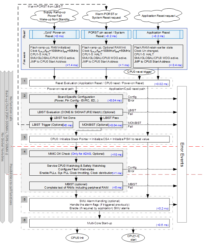
The application start-up code is executed after the Boot firmware. Initialization is carried out by CPU0. Based on the reset event, the start-up software will follow different execution paths. The Application start-up flow described is for reference purpose. The user is allowed to modify this according to their application.
The main steps of the start-up sequence for AURIX™ TC3xx microcontrollers are divided into multiple phases:
- In the first phase, the PSW register is initialized to use the Interrupt Stack Pointer with maximum Call Depth Counter in User-1 mode. Then a reset evaluation is performed to find out whether it is an application reset, power-on reset, or CPU 0 reset.
The second phase has 3 parts:
- Initialize EVR based on the external components used. Then verify the register contents against the required configured values.
- Perform LBIST tests for an in-system health-check, then continue as per the application configuration.
MONBIST checks are made to verify the secondary voltage monitors and alarm generation path. Secondary voltage Monitor BIST ensures higher latent fault coverage for the secondary voltage monitors and the associated alarm and error pin fault logic routed to the Standby SMU.
Note: The second phase is executed only for cold power-on reset. For other resets, this phase is not required because power supplies are already stable.- In the third phase the system is set up to support function calls. This includes setting up the Context Save Area and initialization of the stack pointer (A10). No global variables are used at this stage.
The fourth phase initializes the clock and flash wait-states for the configured clock frequency. In case of the ADAS board before PLL initialization, MMIC chip is enabled. MMIC chip provides a clock to the CPU. MMIC related functionality is implemented as a callout hook function. For safety applications MBIST checks are performed on RAMs (Please refer to the Memory Test Unit (MTU) chapter for further details in the user manual). This initializes and checks the safety of all the RAMs.
This phase is executed only in case of power-on reset. For other resets, this phase is not required because clock and flash modules retain their states through such resets.
- The fifth phase is optional and used for safety applications. This involves SMU alarm handling. This is provided as a hook function which is implemented according to the application requirement.
- The sixth phase involves following steps:
- Enabling cache mechanisms according to configuration (IFX_CFG_SSW_ENABLE_TRICOREx_PCACHE, IFX_CFG_SSW_ENABLE_TRICOREx_DCACHE (where x is a core number)), by setting CPU_PCON, CPU_DCON registers.
- Setting up the system to support interrupt and trap mechanism (Initializing BIV and BTV registers which sets interrupt and trap vector tables).
- Iinitializing global variables for CPU0 and CPU Shared variables
- Starting the additional CPUs as configured
Multi-core start-up occurs in a daisy chain sequence, where one CPU enables the next CPU in sequence. The respective CPU specific C runtime initialization routines are executed. The next step is the transfer of control to OS. In the case of a multi-core OS system, StartCore () and StartOS () function calls are carried out on every CPU. This is followed by the synchronization between the cores, by invoking IfxCpu_emitEvent () and IfxCpu_waitEvent () APIs. In case the AUTOSAR basic software layer is used, alternatively Ecum_Init () function may be called in this step which in turn would trigger OS initialization. Initialization/start-up can be customized between different derivatives or steps of the same derivative by using CHIPID [15:12] and CHIPID [5:4] respectively.

- Any phase, if it ends with an error, __debug () instruction is executed to indicate the erroneous behavior. This can be replaced with a reset or any fault reaction functionality as per the needs of the application.
- Call-out functions needs to be implemented with no function calls until stack and CSA are setup. These functions shall always be ‘inlined’ without using the stack and the registers values used are to be restored manually during return from function.
Phase-wise descriptions
Phase 1: Reset type evaluation
The reset type evaluation is carried out to determine if the last reset was an application, system, or CPU 0 reset.
Based on the result the execution of start-up software is optimised for runtime, where few of the phases are excluded. This evaluation is done by reading the RSTSTAT and RSTCON registers.
The request sources SW, STMx, SMU, ESRx, and CB3 can only generate application resets. All other reset sources can also generate a system reset.
In the case of an application reset, the evaluation function Ifx_Ssw_isApplicationReset () returns a 1. In all other cases it returns a 0. The RSTSTAT is not cleared, since it is used in later phases.

Phase 2: PMS, LBIST, and MONBIST handling
PMS handling
For the applications where VDD core domain power is generated internally with EVRC, its parameter has to be updated depending on application specific requirements. The main reason why the PMS module is initialized here is to support the high current demand that is required for the LBIST execution in the next phase.
SMPS regulator parameters, such as the mode of output MOSFET drivers, the switching frequency shall be adapted. During this phase the EVR register is written with the required configuration.
EVRC Regulator Voltage status is checked to ensure the set-point voltage is reached, by reading the SDVOK bitfield in the EVRSTAT register.
EVR configurations are only done if EVRC is in an active state. EVRC is activated if HWCFG [2] pin level is latched high during start-up phase.
LBIST handling
On completion of a successful PMS initialization, LBIST tests are run if enabled. The Logic-BIST function is a structural test method for automatic in-system health-check of the digital part of the hardware. LBIST schemes use on-chip circuitry to generate test stimuli and analyze test responses.
The first check is to see if a previously triggered LBIST is complete, by reading the LBISTDONE bit in LBISTCTRL0. If LBIST is marked as complete, the result of the last LBIST is checked against the expected value by reading the SIGNATURE bit in the LBISTCTRL3 register. If the LBIST was not started, LBIST is triggered, which results in a warm power-on reset with the same start-up flow as for the cold reset executed by firmware. In particular this is valid for the RAM initialization after LBIST selected with HF_PROCONRAM.RAMIN settings.

LBIST handling in the firmware
LBIST execution can be triggered automatically in the firmware at Cold PORST of the MCU. The load fluctuations introduced by LBIST imply limitations to the core VDD voltage generated by an external core voltage regulator. There is an assumption for this case that an external regulator applies Warm PORST hold time to the MCU of 1ms. This ensures that the core voltage regulator reaches its static region (allowed not more than +-4% of the VDD nominal), and it can successfully response to the load fluctuations during LBIST phase without violation of reset limits.
If VDD is supplied internally by EVRC, it takes care not to violate the VDD 1.2V static under voltage limit (VDD,typ – 4%).
MONBIST handling
The Secondary Monitor and Standby SMU Built in Self-Test (MONBIST) ensures higher latent fault coverage for the secondary monitors and the associated alarm and error pin fault logic routed to the Standby SMU. This is triggered by setting the TSTEN bit of the MONBISTCTRL register in the Standby SMU module, and waiting until the TSTRUN bit is set in the MONBISTSTAT register. The status is verified by reading the TSTOK bit in the MONBISTSTAT register.
Phase 3: Setup system to support Function calls for CPU0
The basic C runtime environment needs to be initialized, before a C-based function to be executed. In this phase of start-up the stack pointer and CSA are setup. Until this phase, function calls and global variables must not be used. Interrupt generation is disabled, but Trap generation and Flash ECC are active.
The start-up code shall initialize the user stack pointer, A10 register.
- The user stack pointer base address and the stack size are configured via linker/locator settings.
- The start-up code has already tested and initialized the memory which is used for stack and align stack boundaries.
The call depth of consecutive context save operations shall be the reset value in PSW (CDC) register.
- The CSA linked list is initialized via PCXI, LCX, and FCX registers.
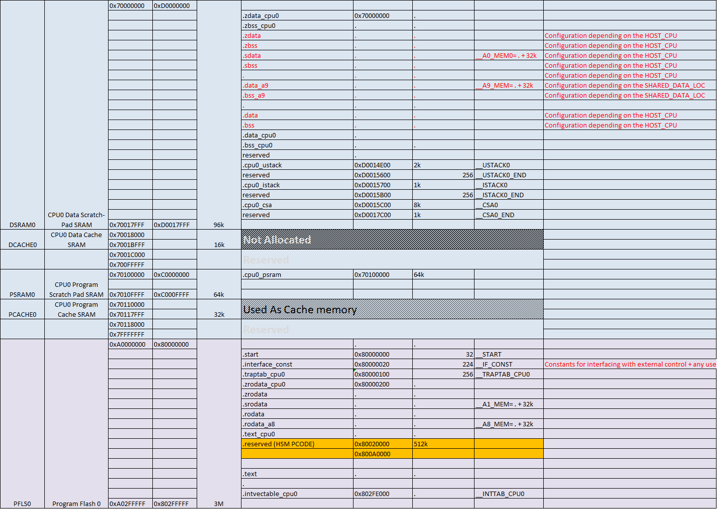
- The CSA area for each core is configurable and is specified in linker scripts (.lsl files) [See Table 4].
Phase 4: Enable PLL and other driver initialization and RAM tests
- The start-up code, depending on the application, may continue to service the internal CPU0 and Safety watchdog until the watchdog is initialized by the watchdog driver. The watchdog service time is increased during start-up to slow down the watchdog so as to reduce overheads due to watchdog servicing. However during initial safety test and initialization phase, it may be required to service the watchdog in between, depending on the time taken for the tests.
- The ADAS board MMIC chip can be enabled to supply the clock to the CPU.
- The next step is to enable, initialize and distribute the clock to the modules (i.e. CPU clocks, Peripheral Clocks, Bus clocks, Pre-scalers, and multipliers which have to be configured in the microcontroller). This includes the initialization of the PLL factors; start PLL lock process and wait till PLL is locked. The clock is configured in steps to avoid large current jumps and the number of steps is a configurable parameter. As a guideline, the DCO frequency is configured to be as high as possible within the DCO min/max limits documented in the datasheet. Ensure to add an appropriate timeout in case of waiting in a loop for DCO lock event, or Kx divider updates for example.
- After PLL configuration, all module dividers and module clocks are re-initialized based on configuration. The current status of the clock shall be checked before configuring the clock and PLL. This is to avoid trying to configure the clock again when it is already configured.
- The wait states for flash access shall be configured into DMU_HF_DWAIT and DMU_HF_PWAIT, based on the clock setting. Activate the pre-fetch buffer and the branch predictor.
- The next step is to run the Non-Destructive tests for the entire RAM area (MBIST).
Phase 5: SMU alarm handling
The SMU is a central and modular component of the safety architecture, providing a generic interface to manage the behavior of the microcontroller under the presence of faults. The SMU centralizes all the alarm signals related to the different hardware and software-based safety mechanisms. These alarms are handled in this phase.
Phase 6: C initialization and multi-core start-up
C initialization
The Cache memory for data and/or code is tested, initialized, and enabled.
- PCON and DCON registers are initialized to enable program and data cache based on the configuration (IFX_CFG_SSW_ENABLE_TRICOREx_PCACHE, where x is a core number).
- The cache needs to be invalidated before initialization. A minimal amount of Cache may be tested and activated at the beginning to save time.
Address registers A0, A1, A8, and A9 are system global registers and are initialized here.
- By convention, A0 and A1 are reserved for compiler use.
- A8 and A9 are reserved for OS or application use.
- A0 is used as a base pointer to the small data section, where global data elements can be accessed using base + offset addressing.
- A1 is used as a base pointer to the literal data section.
The Ssw_C_Init () is run to initialize the global variables.
- Global memory regions are cleared where global C variables, arrays (.bss, .sbss) are located. The general practice on a microcontroller is to loop over this uninitialized (or zeroed) global memory region and set all bytes to 0 at start-up.
Initialize the base addresses for interrupt and trap vector tables, in BIV and BTV registers of each individual core.
- These base addresses are configurable via linker/ locator settings.
The start-up code shall initialize the Interrupt Stack Pointer (ISP) register if an interrupt stack is supported.
- The interrupt stack pointer base address and the stack size are provided as configuration parameters via linker/locator settings.
- BTV, BIV, and ISP are CPU ENDINT protected registers.
The Ifx_Ssw_Init () function, copies variable initialization values from Flash to RAM, if needed.
- This may apply to variable data segments and static values in functions.
- Linker/locator settings ensure the proper relocation of symbols to the addresses in RAM.
- Application specific RAM initialization from Flash may be also carried out later.
CPU Class 0 to Class 7 CPU TIN traps are activated.
- These include MPU, Internal protection, Instruction error, Context Management, System Bus, and Peripheral errors, Assertion, System Call, and NMI traps.
- The trap status flags shall be cleared before activation of the respective traps.
- An interrupt may continue to remain disabled until an OS call is invoked, depending on application requirements.
Multi-core start-up
Additional CPUs are started after the clock is initialized to reduce the current jumps, as starting each CPU introduces a current jump of ~100mA.
If a shorter start-up time and higher performance during start-up is required then the CPUs can be started earlier.
The hardware only starts the CPU0 core by default, while the other cores remain in HALT state until they are explicitly activated by software by clearing the BHALT bit in the SYSCON register.
Each Core finds itself in one of the four states; Reset state, HALT Mode, IDLE Mode, or RUN Mode.
- The CPU states can be configured using the SYSCON and PMCSRx registers.
The PC value of a halted CPU has to be configured before moving the CPU from HALT to RUN mode.
- The PC address of a CPU is offset to the CPU base address which can be derived from a method IfxCpu_getAddress (CpuId) to know the absolute PC address.
- For address translation between the local CPU address and global address which may be used by other CPUs or DMA, a method such as IFXCPU_GLB_ADDR_DSPR (cpu, address), IFXCPU_GLB_ADDR_PSPR (cpu, address) may also be used.
If a core is activated, it first executes the respective start-up flow before the ‘main’ function is called.
- In case the same ‘main’ function is executed on each core, the cores have to be differentiated by their specific core Id within the function.
- A hook is provided to carry out CPU specific configurations.
When CPUx has not been tested or activated earlier, we would have to use the HALT to RUN mode to activate the CPU.
- In case they were activated earlier, these CPUs would be set into IDLE mode. They can be re-activated by switching them from IDLE to RUN mode.
- Exit from HALT mode is handled in the SYSCON register.
- Entry/exit from IDLE mode is handled in the respective PMCSR registers.
Software interrupts are capable of being passed between any of the CPUs.
- Interrupt sources and DMA triggers can be configured or allocated to any set of CPUs.
- Activation of the cores is also possible via OS specific methods.
The Lockstep core is implicitly started via firmware based on the BMI configuration.
- The LCLCONx.LS register status bit indicates whether the Lockstep cores are currently active.
EMEM initialization
Extension memory (EMEM) can be used for an application (ADAS), calibration, or trace data storage.
EMEM is only present in the Emulation and ADAS extension devices.
A software hook is provided to enable the initialization of EMEM.
- The SCU CHIPID register is read to check if the emulation or ADAS extension hardware is available or not.
- If the emulation or ADAS extension hardware is available, then EMEM is enabled by writing into EMEM_CLC register.
- The EMEM is unlocked by writing the sequence specified into the SBRCTR register.
Implementation
Files and folder descriptions
| File name | Description |
|---|---|
Ifx_Ssw_Tc<core no.>c/.h | The file contains core specific software start routines |
Ifx_Ssw_Compilers.h | The file contains includes for the compiler selected |
Ifx_Ssw_Infra.c/.h | The file contains the utility functions used in the software start up software |
Ifx_Cfg_Ssw.c/.h | The file contains the sample call-out implementations for the software start-up software |
Ifx_Cfg_SswBmhd.c | The file contains the example Boot Mode Headers |
Callout functions
The following sections provide details on different call-out functions and sample implementations.
IFX_CFG_SSW_CALLOUT_PMS_INIT
| Syntax | IFX_CFG_SSW_CALLOUT_PMS_INIT() |
| Sync / Async | Synchronous |
| Reentrancy | Non- Reentrant |
| Enable | The example implementation is enabled by setting the IFX_CFG_SSW_ENABLE_PMS_INIT macro to 1, in the Ifx_Cfg_Ssw.h file. |
| Implementation Restriction | This callout function shall not be implemented as a function call. |
| Description | This needs to be configured by the application to initialize the PMS EVR module. This hook is by default defined to an empty call in the start-up implementation. |
IFX_CFG_SSW_CALLOUT_LBIST
| Syntax | IFX_CFG_SSW_CALLOUT_LBIST() |
| Sync / Async | Synchronous |
| Reentrancy | Non- Reentrant |
| Enable | The example implementation is enabled by setting the IFX_CFG_SSW_ENABLE_LBIST macro to 1, in the Ifx_Cfg_Ssw.h file. |
| Implementation Restriction | This callout function shall not be implemented as a function call. |
| Description | This needs to be configured by the application to perform LBIST tests. This hook is by default defined to an empty call in the start-up implementation. |
IFX_CFG_SSW_CALLOUT_MONBIST
| Syntax | IFX_CFG_SSW_CALLOUT_MONBIST() |
| Sync / Async | Synchronous |
| Reentrancy | Non- Reentrant |
| Enable | The example implementation is enabled by setting the IFX_CFG_SSW_ENABLE_MONBIST macro to 1, in the Ifx_Cfg_Ssw.h file. |
| Implementation Restriction | This callout function shall not be implemented as a function call. |
| Description | This needs to be configured by the application to perform MONBIST tests. This hook is by default defined to an empty call by the start-up implementation. This function is available for 39Bx and 38x devices. |
IFX_CFG_SSW_CALLOUT_MMIC_CHECK
| Syntax | IFX_CFG_SSW_CALLOUT_MMIC_CHECK() |
| Sync / Async | Synchronous |
| Reentrancy | - |
| Enable | The default implementation is enabled by setting the IFX_CFG_SSW_ENABLE_MMIC macro to 1, in the Ifx_Cfg_Ssw.h file. |
| Implementation Restriction | No restrictions. |
| Description | This is defined as an empty function. This functionality shall be implemented according to the application. |
IFX_CFG_SSW_CALLOUT_ PLL_INIT
| Syntax | IFX_CFG_SSW_CALLOUT_PLL_INIT() |
| Sync / Async | Synchronous |
| Reentrancy | Non- Reentrant |
| Enable | The example implementation is enabled by setting the IFX_CFG_SSW_ENABLE_PLL_INIT macro to 1, in the Ifx_Cfg_Ssw.h file. |
| Implementation Restriction | No restrictions. |
| Description | This needs to be configured by the application to set the clock to the maximum frequency. This hook is by default defined to an empty call by the start-up implementation. |
IFX_CFG_SSW_CALLOUT_ MBIST
| Syntax | IFX_CFG_SSW_CALLOUT_MBIST() |
| Sync / Async | Synchronous |
| Reentrancy | Non- Reentrant |
| Enable | The example implementation is enabled by setting the IFX_CFG_SSW_ENABLE_MBIST macro to 1, in the Ifx_Cfg_Ssw.h file. |
| Implementation Restriction | No restrictions. |
| Description | This needs to be configured by the application to perform MBIST tests. This hook is by default defined to an empty call by the start-up implementation. |
IFX_CFG_SSW_CALLOUT_SMU
| Syntax | IFX_CFG_SSW_CALLOUT_SMU() |
| Sync / Async | Synchronous |
| Reentrancy | - |
| Return Value | The example implementation is enabled by setting the IFX_CFG_SSW_ENABLE_SMU macro to 1, in the Ifx_Cfg_Ssw.h file. |
| Implementation Restriction | No restrictions. |
| Description | This is defined as an empty function. This functionality shall be implemented according to the application. |
IFX_CFG_SSW_CALLOUT_EMEM_INIT
| Syntax | IFX_CFG_SSW_CALLOUT_EMEM_INIT() |
| Sync / Async | Synchronous |
| Reentrancy | - |
| Return Value | The example implementation is enabled by setting the IFX_CFG_SSW_ENABLE_EMEM_INIT macro to 1, in the Ifx_Cfg_Ssw.h file. |
| Implementation Restriction | No restrictions. |
| Description | This needs to be configured by the application to initialize the EMEM. This hook is by default defined to an empty call by the start-up implementation. |
Linker/Locator settings
| Symbol | Description |
|---|---|
__ISTACK<core number> __ISTACK<core number>_END | Interrupt stack start and end address for each core |
__USTACK<core number> __USTACK<core number>_END | User stack start and end address for each core |
__CSA<core number> __CSA<core number>_END | Context save area start and end for each core |
| __INTTAB<core number> | Interrupt vector table pointer (BIV) |
| __TRAPTAB<core number> | Trap vector table pointer (BTV) |
| _SDATA1<core number> | A0 addressable area address |
| _SDATA2<core number> | A1 addressable area address |
| _SDATA3<core number> | A8 addressable area address |
| _SDATA4<core number> | A9 addressable area address |
Sample memory map definitions on CPU0
Application software
After completion of the start-up software, the main () function is invoked with zero call depth. In this function the user can implement function calls and other peripheral initialization. Depending on the application, hardware tests can also be added. Additionally, OS init is invoked to setup the OS environment.
Start-up aspects
HWCFG (Pin configuration)
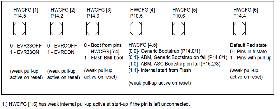
HWCFG [1:2] shall always be configured to select the required Supply mode.
- This configuration activates the internal EVRC (SMPS or LDO mode) and/or EVR33 (LDO) for 1.25V and 3.3V supply generation.
- It should be ensured that these pins are at their intended levels via internal or external pull devices during supply ramp-up to avoid accidental entry in other supply modes.
- The latched pin status is reflected in PMSWSTAT.HWCFGEVR status bits and may be checked along with EVRSTAT register to ensure that the selected supply mode is the intended one.
- HWCFG [1:2] is latched during initial supply ramp-up and not on warm PORST pin assertion.
HWCFG [3] is the BMI selection pin and decides whether the boot configuration shall be taken from HWCFG [4:5] pins or from a Boot Mode Index address in Flash BMI.
- The rationale to use Flash BMI for boot mode selection is to save pins and to avoid security loopholes. BMI.PINDIS bit decides whether HWCFG [3:5] pins shall be used at all for boot selection.
- HWCFG [3] is latched during initial supply ramp-up and not on warm PORST pin assertion.
HWCFG [4:5] needs to be configured for primary bootstrap mode selection only if HWCFG [3] is configured to boot from pins instead of Flash. In case Flash is used to boot, these pins are ignored.
- ABM, Generic Bootstrap on P14.0/P14.1 is recommended as this is the default boot loader mechanism for a virgin flash or on boot failure.
- Generic Bootstrap means CAN or ASC boot loader client is automatically detected and the respective boot loader procedure is started.
- HWCFG [4:5] is latched after warm PORST pin assertion if HWCFG [3] and BMI header allows boot from pins.
- In general HWCFG [4:5] pins are not used as it is usual to boot completely from Flash BMI.
HWCFG [6] decides whether port pins are by default in tri-state or behave as inputs with pull-up devices activated during and after reset.
- The default pull-up on HWCFG [6] ensures that all pins have default pull-up state if this pin is left unconnected. HWCFG [6] is latched during initial supply ramp-up and not on warm PORST pin assertion.
| HWCFG pins | Function |
|---|---|
HWCFG [1] P14.5 | 0 - EVR33OFF 1 - EVR33ON |
HWCFG [2] P14.2 | 0 - EVRCOFF 1 - EVRCON |
HWCFG [3] P14.3 | 0 - HWCFG boot 1 - Flash BMI |
HWCFG [4] P10.5 | Bootstrap 00- Gen P14.0/1 01- ABM, Gen P14.0/1 10- ABM, ASC P15.2/3 11- Flash |
HWCFG [5] P10.6 | |
HWCFG [6] P14.4 | 0 - Pins in tristate 1 - Pins with pull-up |
VGATE1P P32.1 | P Ch. MOSFET gate drive |
VGATE1N P32.0 | N Ch. MOSFET gate drive |
CRC calculation for BMI
During evaluation of the BMI headers, the Boot firmware calculates the CRC and inverted CRC checksum over the BMHDx content (total 2 words including BMI, BMHDID and STAD). It also compares against the CRCBMHD and CRCBMHD_N values stored inside BMHDx.
If ABM mode is selected the Boot firmware calculates the CRC and inverted CRC checksum over the ABMHD content (total 6 words including STADABM, ABMHDID, CHKSTART, CHKEND, CRCRANGE and CRCRANGE_N) and compares against the CRCABMHD and CRCABMHD_N values stored inside ABMHD.
It is necessary to calculate the CRC and inverted CRC checksum for the Boot mode headers and program the values. The CRC generator polynomial used is the CRC-32 polynomial as defined in the IEEE 802.3 standard. The CRC result produced is bit-reflected and inverted as per the IEEE 802.3 standard (CRC32 generator polynomial is 0x04C11DB7h).
The CRC instruction of TriCore™ is used for the CRC calculations in the BMI header. Endianness and orientation need to be taken care of. Though the memory byte ordering is arranged in little- Endian order (least-significant bytes are at lower addresses), the CRC calculation considers big- Endian order (most significant bytes are at lower addresses). The CRC algorithm treats input data as a stream of bits. Exactly 32 bits of input data are processed. The four bytes in the input word are processed in big-endian order; the most significant 8 bits are processed first, and the least significant 8 bits are processed last. Within each 8-bit byte, the least significant bit is processed first, and the most significant bit is processed last.
Code Listing 1 CRC Checksum code example using TriCore™ CRC instruction
001	#include "Ifx_Types.h"
002	uint32 IfxCpu_calculateCRC32(uint32 *array, uint32 size)
003	(
004	  uint32 i;
005	  uint32 crc32=0;
006	  for(i=0; i<size; i++)
007	  (
008	    uint32 tempVar=array[i];
009	  #ifdef GNUC
010	    asm volatile ("crc32 %0, %1, %2": "=d" (crc32) : "d" (tempVar) , "d" (crc32));
011	  #endif
012	  )
013	  return crc32;
014	)
The pass pointer of an array holds the BMI header and start address, and includes the size to get the CRC value using the CRC instruction provided by TriCore™.
CPU Interrupt and Trap handling
Interrupt handling
The interrupt management in TriCore™ Architecture provides hardware support for minimizing interrupt latency, for saving/restoring context, and for clearing the service request flag (SRR).
When the interrupt is acknowledged, a global interrupt disable on ISR entry is performed automatically by hardware. The Interrupt Router module includes one ICU (Interrupt Control Unit) per service provider which manages the arbitration among competing service requests from SRN (Service Request Nodes) and provides the winner of the arbitration round to the service provider as shown in Figure 10. Each service provider, a CPU or DMA, can handle up to 255 interrupts or priority levels from the total available pool of 516/1024 interrupt/service requests.

Interrupt Service Routines are linked via Service Request Priority Numbers by an Interrupt Vector Table located in each CPU.
- The CPU Interrupt Vector Table itself is ordered by priority number.
- On taking an interrupt, the CPU will vector to a unique PC address generated from the offset of the interrupt priority number to the Base Interrupt Vector (BIV) as shown by jump in Figure 10.
- The CPU Interrupt Vector Tables therefore allow a single peripheral to have multiple priorities for different purposes.
Interrupt Vector Table is installed at link time or dynamically installed by software interrupt installation handlers. This associates the ISR function to the vector table entry/SRPN priority and ensures that the vector table entry for the interrupt, points to the start address of the respective ISR so that the jump can take place as shown in Figure 10.
- It is possible to have multiple interrupt vector tables and switch between them simply by modifying the contents of the BIV register as maybe done by OS.
- Alternatively a single interrupt vector table may also be realized across all the CPUs if 255 interrupts are enough on the system level. In this case CPU0_BIV, CPU1_BIV … CPUn_BIV all initialized, to point to the same vector table __INTTAB location.
The base address of the interrupt vector table is by default set to BIV=0000 0000h after reset, and is initialized using the MTCR instruction during Start-up phase.
- The first table entry (SRPN = 0000h) is reserved and must not be used for service requests mapped to a CPU.
- The BIV base address shall be aligned to an even byte / half word address boundary.
All Service Request Nodes are disabled by default after reset. To use a Service Request Node, it has to be configured and enabled by setting the respective SRC.SRE bit=1.
- If SRE = 1, a pending service request takes part in the interrupt arbitration of the service provider ICU selected by the device’s TOS bit field.
- Before modifying the TOS or an SRPN bit field, the corresponding SRN must be disabled (SRE = 0).
- Clearing a pending service request flag SRR and enabling the corresponding service request node (SRN) should be done in two steps / two writes; first clear the SRR flag (SRC.CLRR), then enable the (SRC.SRE).
Globally, Interrupts are disabled by default after reset.
- Before an interrupt can occur, the interrupt system has to be globally enabled.
- The Interrupt Control Register (ICR) holds the global interrupt enable bit (ICR.IE) which enables the respective CPU ICU to forward interrupts.
| 1 | Initialization of Base Interrupt Vector address:
|
| 2 | Installation of the Interrupt handler in Vector table at link time:
|
| 3 | Installation of the Interrupt handler in Vector table managed via software:
|
| 4 | Definition of interrupt service routine:
|
| 5 | Configuration of Service request Node :
|
| 6 | Activating the Service request Node to participate in the respective ICU arbitration:
|
| 7. | Global Interrupt enable:
|
Trap handling
A trap occurs as a result of an event such as:
- a Non-Maskable Interrupt
- an instruction exception
- a _syscall ()
- an illegal access
- The available traps are divided into 8 trap classes (TCN).
- Traps are also classified as synchronous, asynchronous, hardware and software traps.

Trap Service Routines are linked via Trap Class Numbers to a Trap Vector Table specific to each CPU.
The Trap Vector Table itself is ordered by trap class numbers which are used to index into the trap vector table.
Each trap class is assigned a Trap Service Routine (TSR), which is served as soon as the trap of this class occurs.
On taking a trap, the CPU will vector to a unique PC address generated from the offset of the trap class number (TCN) to the Base Trap Vector (BTV) as shown by jump in Figure 11 .
A trap does not change the CPU interrupt priority of the program which triggers it, so the ICR.CCPN field is not updated. The CPU aborts the instruction in progress when a trap occurs and forces execution of the appropriate TSR.
Each trap is additionally assigned a Trap Identification Number (TIN), which identifies the cause of the trap within its class. The Trap Identification Number (TIN) is loaded into the data register D [15] on TSR entry.
D [15] may be read in TSR to decipher the reason behind the trap.
Trap service routine shall be implemented as normal functions and TSR pointers are installed in trap vector tables as defined either by OS or by compiler specific configuration file. When OS is used in the application, normally trap handling is taken care inside OS implementation. The trap functions for each TCN class for each CPU (x= 0, 1, 2) are enumerated as follows:
- CoreX_tsrMmu()
- CoreX_tsrProtection ()
- CoreX_tsrInstruction()
- CoreX_tsrContext()
- CoreX_tsrBus ()
- CoreX_tsrAssertion ()
- CoreX_tsrOSSystemCall()
- CoreX_tsrNMI()
A Trap Vector Table is statically installed at link time or dynamically installed by software trap installation handlers to associate the TSR function to the vector table entry/ trap classes. This ensures that the vector table entry for the interrupt points to the start address of the respective TSR, so that the jump can take place as shown in Figure 11.
It is possible to have CPU individual trap vector tables. Alternatively a single trap vector table may also be realized across all the CPUs with core specific branches in TSR if required. In this case CPU0_BTV, CPU1_BTV … CPUn_BTV are all initialized to point to the same trap table __TRAPTAB location.
The base address of the trap vector table is by default set to BTV=0x80000100 after reset and shall be initialized using the MTCR instruction during the start-up phase. The trap table is located in the non-cached region to also react to Cache traps. The first table entry (TCN = 00h) is reserved as MMU is not supported. The BTV base address shall be aligned to a 256 Byte address boundary.
Traps are always active and cannot be disabled.
Synchronous traps are taken immediately on the attempted execution of specific instructions and serviced before execution can proceed beyond that instruction.
Asynchronous traps are similar to interrupts, in that the cause of the trap is detected externally to a core and is signalled back to the core.
Software traps involve system calls, assertion traps, or NMI.
| 1 | Initialization of Base Trap Vector address:
|
| 2 | Installation of the Trap handler in the Vector table at link time: This depends on linker/compiler choice and is defined in the respective linker script file. Trap vector table entries are initialized with the respective TSR entry address at link time. |
| 3 | Installation of the Trap handler in the Vector table managed via software:
|
| 4 | Definition of trap service routine:
The default trap routine may, in the development phase, include a _debug () function for easy debugging of the trap. |
Secondary Boot-loader handling
The secondary Boot-loader and Application usually have separate instances of the start driver.
- It is to be evaluated whether the secondary Boot-loader driver instance or the application driver instance for start-up need to be executed. This is decided based on an ‘application presence’ flag. If an application is present, a jump directly to the application instance needs to be executed. If not, a jump to the Boot-loader driver instance takes place. This flag variable is stored in NVM memory – Dflash or external EEPROM. The flag variable may be updated by both boot-loader and application software.
- If the RAM test is performed by the boot-loader, then it is usually not done in the application, and vice-versa.
A clock may be configured in the Boot-loader if CAN is used for secondary boot loading.
- Other drivers may also be used in the Boot-loader, such as CAN, SCI, Flash, Digin, Digout, SPI, and IRQ for example.
- The Boot-loader instance usually has static scheduling for tasks.
A method JumpToAppl (…) allows jumping from the Boot-loader driver instance to the application driver instance. The application is to take care that before the jump:
- Interrupts and DMA are disabled by boot-loader before jump to application driver instance
- Modules used in the boot-loader shall be set back to reset status. It is especially important to ensure that the clock register state does not cause issues when the clock is re-initialized by the application instance.
Logic-BIST
The Logic-BIST (LBIST) function is a structural test method for an automatic in-system health-check of the digital design. LBIST schemes use on-chip circuitry to generate test stimuli and analyze test responses, without any help from an external test system.
LBISTCTRL0, LBISTCTRL1, LBISTCTRL2 are the available configuration registers. After configuring these registers LBIST operation is started by setting the LBISTCTRL0.LBISTREQ bit.
LBIST execution always terminates with a system warm reset. A successfully finished LBIST procedure is indicated by the LBISTCTRL2.LBISTDONE bit.
Based on the configuration during execution of the LBIST a unique signature is generated and updated in LBISTCTRL2.SIGNATURE field. This signature allows application software to check if the MCU was tested by LBIST with or without errors.
MBIST
The internal memories within the AURIX™ TC3xx family of microcontrollers have a unified interface for the control of BIST (Built-in-Self-Test), ECC (Error Correction), and redundancy features. This interface can also be used to fill the memories with a pre-defined data value for initialization. The MTU controls and monitors these memory tests, initialization, and data integrity checking functions.
In order to check the integrity of the SRAM and its contents, an MBIST may be run by configuring the SSH. The test type and parameters are programmed via the SSH registers, CONFIG0 and CONFIG1, and certain parameters via the MCONTROL register.
The advantage of using MBIST is direct access to the memories without using the CPU. Even small memories that are not directly accessible via the CPU can be tested using MBIST.
RAMs are grouped into so-called ‘gangs’ and MBIST checks are done on groups sequentially. This avoids the big jumps in the supply current. All the RAMs in a Gang are processed in parallel. For example TC39xB RAMs are grouped into 17 gangs for initialization.
| Gang number | RAM list | ||
|---|---|---|---|
| 0 | EMEM0 | M_CAN10 | - |
| 1 | EMEM1 ERAY_MBF0 | M_CAN20 | M_CAN21 |
| 2 | EMEM2 | ERAY_MBF1 | - |
| 3 | EMEM3 | - | - |
| 4 | CPU0_DMEM | CPU1_DMEM | GTM_DPLL2 |
| 5 | CPU0_DMEM1 HSPDM_RAM | CPU1_DMEM1 | SCR_XRAM |
| 6 | CPU0_DLMU_STBY GTM_FIFO | LMU00 | LMU10 |
| 7 | CPU2_DMEM GIGETH_RX_RAM | LMU20 SDMMC_RAM | GTM_MCS0SLOW |
| 8 | CPU3_DMEM | CPU4_DMEM | - |
| 9 | CPU5_DMEM | SPU_CONFIG0 | SPU_CONFIG1 |
| 10 | CPU3_DLMU CPU4_DLMU | CPU5_DLMU GIGETH_TX_RAM | DAM0 DAM1 |
| 11 | CPU0_PMEM GTM_MCS0FAST | CPU1_DLMU_STBY GTM_MCS1FAST | CPU2_DLMU PSI5 |
| 12 | CPU1_PMEM | CPU2_PMEM | CPU3_PMEM |
| 13 | CPU0_PTAG MCDS | CPU4_PMEM EMEM_XTM | CPU5_PMEM |
| 14 | CPU1_PTAG CPU3_PTAG CPU5_PTAG SPU_BUFFER1 | CPU2_PTAG CPU4_PTAG SPU_BUFFER0 GTM_DPLL1BC | - |
| 15 | CPU0_DTAG CPU2_DTAG CPU4_DTAG SADMA ERAY_OBF0 ERAY_TBF_IBF0 SPU_FFT00, 01, 10, 11, 20, 21 | CPU1_PTAG CPU3_DTAG CPU5_DTAG GTM_DPLL1A ERAY_OBF1 ERAY_TBF_IBF1 | - |
| 16 | SPU_FFT30 | SPU_FFT31 | - |
Power management
On-chip linear and switch mode voltage regulators are implemented in the AURIX™ TC3xx family of products, so enabling a single source power supply concept.
The external nominal system supply from external regulator may be either 5 V or 3.3 V. The Embedded Voltage Regulators (EVR33 and EVRC) generate the VDDP3 and VDD supply voltages required internally for the core and flash domains.
- The EVRC regulator is implemented as an SMPS regulator and generates core supply either from 5 V or 3.3 V external supplies.
- The EVR33 regulator always implemented as a LDO regulator and is required only in case of 5 V external supplies.
All supply and generated voltages are monitored for brownout conditions by primary monitors setting the device into cold power-on reset state if there is a violation.
All supply and generated voltages are also monitored redundantly by secondary monitors against programmable over-voltage and under-voltage levels. If these levels are violated, either an interrupt or an alarm to the SMU will be generated.
The choice of the supply scheme at start-up is based on the latched status of the HWCFG [2:1] pins before cold PORST release, and is indicated by the PMSWSTAT.HWCFGEVR status flags.
Clock system
At reset, the AURIX™ TC3xx product starts with an internal clock source of 100 MHz for the CPU and 50 MHz for peripherals.
During the driver initialization phase, the PLL is configured based on an external crystal or resonator clock source, and the clock configuration.
Methods are provided to enable, initialize, and distribute the clock to the modules (CPU clocks, Peripheral Clocks, Bus clocks, Pre-scalers, and multipliers which have to be configured in the microcontroller). This includes the initialization of the PLL factors; start PLL lock process and wait till PLL is locked.
- The clock is configured in steps to avoid large current jumps and the number of steps is a configurable parameter.
- As a guideline the DCO frequency is configured to be as high as possible within the DCO min/max limits documented in the appropriate datasheet.
After PLL configuration, various module dividers and module clocks are initialized based on configuration.
- It is possible to have a constant clock for timers (STM / GTM), communication interfaces (QSPI / ASCLIN), and ADC, as these are independent of the CPU or SRI / SPB bus frequency changes.
The current status of the clock is checked before configuring the clock and PLL. This is to avoid trying to configure the clock again when it is already configured.
- The actual configuration shall either represent a user configuration, a reset configuration, or be undefined.
- In the case of a reset configuration or an undefined configuration, the clock shall be re-initialized.
- An additional waiting period (say 1000 cycles) for crystal stabilization maybe added depending on the respective crystal start-up time if required.
A method to get the PLL status is provided.
- The driver provides a service to query the lock status of all PLLs in the microcontroller, individually.
- This service shall return: Locked, Un-Locked, or unsupported.
- A basic mechanism to recover from clock failures to switch to a back-up clock, say a 100 MHz internal clock, is supported by the Hardware.
- The wait states for flash access are configured based on user configuration, as this is dependent on the clock setting.

Watchdog handling
The Watchdog Timers (WDTs) provide a secure way to detect and recover from software and hardware failures. They help to abort a malfunctioning CPU based system within a user specified time period.
End-of-Initialization
Each WDT incorporates an End-of-Initialization (ENDINIT) feature which protects the critical AURIX™ TC3xx registers from accidental and unauthorized write accesses.
To ensure correct WDT servicing and modification of the ENDINIT bit, an access error detection mechanism is implemented to prevent accidental and incorrect write accesses to the WDT control registers.
Any write access to the WDT control registers with an invalid password (during first access) or incorrect value for the guard bits (during second access) triggers a Watchdog alarm request to the Safety Management Unit (SMU).
After a valid write access that clears the ENDINIT bit, the Watchdog imposes a time limit for this access window. If the ENDINIT bit has not been set again within this time limit, the system is assumed to have malfunctioned, and the Watchdog alarm is reported to the SMU.
The SMU could be configured to generate an interrupt or Non-Maskable Interrupt (NMI) to provide some time for recovery or status recording, before further action is taken, such as a reset, or moving the CPU to an idle state for example.
CPUs
After a reset, CPU0 is in RUN mode and CPU0 WDT starts automatically.
Other CPUs are initially in a HALT state and their corresponding WDTs are therefore disabled.
A CPU Watchdog may only be configured, enabled or disabled by its corresponding CPU.
Safety Watchdog
The Safety Watchdog protects critical system registers from accidental and unauthorized write accesses, and provides an overall system Watchdog that is independent from any CPU Watchdogs.
When enabled, the Safety Watchdog Timer (WDT) can trigger an SMU alarm request if it is not correctly serviced within a user programmable time period. Periodic servicing of the Safety WDT therefore confirms that the system is functioning correctly.
Typically the SCU write protection (ACCEN) will be configured so that only ‘Safety’ CPU(s) can configure and service the Safety Watchdog. In addition the Safety Watchdog configuration, enable, and disable functions all require a Safety ENDINIT password.
Revision history
| Document revision | Date | Description of changes |
|---|---|---|
V1.0 | 2017-12-11 | First release. |
V1.1 | 2018-09-10 | Figure 9 updated. Chapter “3.2.2.2 LBIST Handling” updated. |
V1.2 | 2018-10-10 | Minor description improvements in chapters 2.2.1; 3.1; 3.2.3; 3.2.4 Chapter 3.2.6.3 added. Callout function as chapter 3.3.2.8 added. Figure 12 updated. Chapter “3.2.2.2 LBIST Handling” updated. |
V1.3 | 2022-11-30 | VCO with DCO replaced EVR13 with EVRC replaced 1.3V with 1.25V replaced 2nd Generation AURIX™ with AURIX™ TC3xx replaced 2nd Generation with TC3xx replaced (except AppNote name) Chapter 5.8 point 3 (workaround for TC2xx PLL_TC.005) removed (not applicable) |
| V1.4 | 2024-04-17 | Template update Updated the document title Updated the Acronyms and definitions in the About this document section Updated System reset Updated Analog power-up Updated Steps involved in Boot Firmware Updated Boot Mode Header Updated Bootstrap Loader Updated Application start-up software Updated Phase 1: Reset type evaluation Updated HWCFG (Pin configuration) Updated Table 7 Updated Trap handling Updated Figure 11 Updated Logic-BIST Updated MBIST Updated Power management Updated Figure 12 |