AN1100 FuSa in a Nutshell - Electric Power Steering application
32-bit TriCore™
AURIX™ microcontroller
About this document
Scope and purpose
As requirements from functional safety standards in automotive, industrial and other fields are a challenging subject, this document intends to provide a first set of guidelines for users who are unfamiliar using the AURIX™ TC3xx microcontroller unit (MCU) in a functional safety scope.
This application note is part of a series of document named "FuSa in a nutshell" as listed in
5
.
Intended audience
This document is intended for all those evaluating the AURIX™ TC3xx MCU, including functional safety engineers on the customer side and application engineers. This includes designers of safety-related systems who:
Are new to functional safety
Want to know more about functional safety (also called "FuSa") applications
Want to understand in principle how functional safety can be implemented with hardware support
Are looking for functional safety details that cannot be found in the MCU user manual
Structure of the document
This document wants to provide a first guidance on the following safety related arguments:
Electric Power Steering system and safety considerations
Chip set for an ASIL D use case
New trends
Disclaimer
Information include in ths document are for training purposes only and are not to be taken as a blueprint for productive development.
Introduction
To better understand how AURIX™ TC3xx safety features are employed, it is important to discuss a typical application from the automotive sector (an electric power steering (EPS)). A complete chipset, meeting ISO 26262 requirements and supporting fail-safe EPS systems, will be described.
Note: High availability and fail-operational reliability can be achieved by adding a redundant functional system.
The EPS system assists a driver to steer the vehicle with less manual force. The application example of an EPS solution is presented in
Figure 1
.
Figure 1. EPS application example
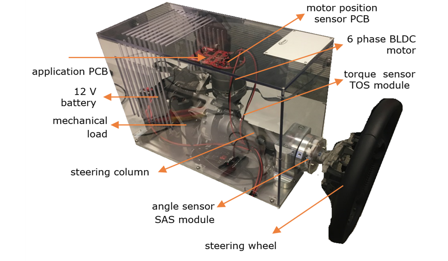
The electronic control unit (ECU) directly controls an electric brushless direct current (BLDC) motor with 3, 6 or 12 phases, which applies additional torque or force to the steering column or directly to the steering rack. The main hazard is “unwanted steering” which is detected within a fault-tolerant time interval of in the order of milliseconds. The ASIL rating assigned is D.
The critical safety hazard "unwanted steering" comprises faults that lead to unintended generation of torque or moves by the BLDC motor that may lead to steering the vehicle in a hazardous direction. In the event of a detected error, the EPS system will inform the driver with a warning and the driver must be able to control the vehicle manually without interference from the EPS system.
Figure 2. Simplified block diagram of an EPS system
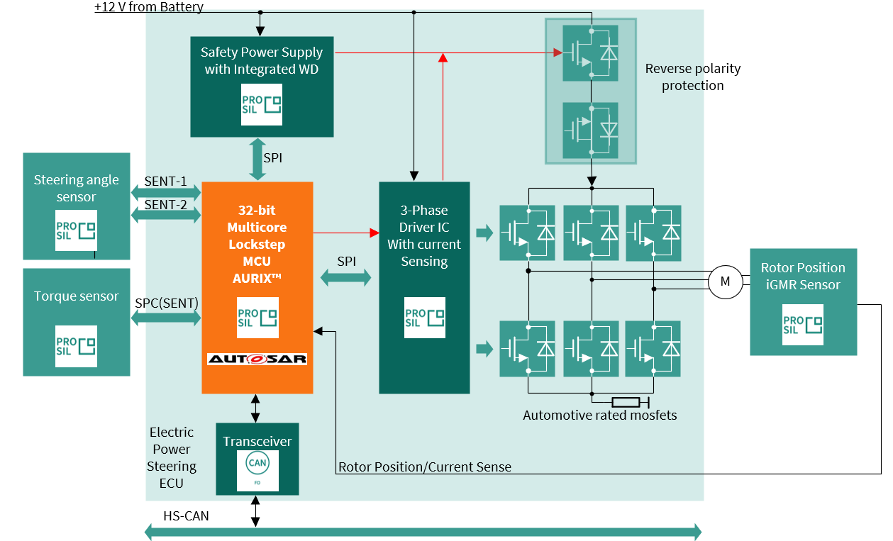
To perform specific tasks, such as steering angle measurement and electric motor control, a number of dedicated integrated circuits are utilized, which are discussed in the subsequent sections. Moreover, their requirements in terms of functionalities and safety-related specifications are described.
Initial assumptions
This example does not cover the steer-by-wire use case; therefore, mechanical steering is considered to be still present. However, the basic requirements for a fail-safe EPS also apply in steer-by-wire systems for each of the redundant functional channels.
Need for protection
EPS uses an electric motor to assist in the steering of a vehicle. A sensor detects the torque exerted on the steering wheel by the driver and an ECU applies assisted torque via the motor. The mechanical linkage between the steering wheel and the steering gear is retained as a backup, so the driver can manually steer the car.
System safe state:
Current flow to the motor is cut off and the motor remains in freewheeling (phase cut-off or active freewheeling). Fail operational may be required, especially for heavy vehicles.
Note: To have a high-availability use case, the example available in this section needs to be reviewed using redundancy.
The EPS system description is represented in
Figure 2
. The main block is the AURIX™ TC3xx microprocessor, which handles and controls all the major functionalities.
Hardware components
The major requirements and the key features of the selected components are:
Safe system supply optimized for EPS with ASIL-D monitoring and supervision
Safe bridge driver, optimal for EPS and brake booster, supporting ASIL-D for safe state off
ISO 26262 compliant angle sensor, torque sensor and motor position sensors designed for most demanding safety applications (ASIL-D) with superior accuracy performance
Robust MOSFET with superior switching behavior
AURIX™ TC3xx- microcontroller that needs to guarantee safe calculation because the output values of the control algorithms heavily influence the generation and control of the BLDC motor. In addition, PWM signals (typically at 20 kHz) for the high side and the low side switches of the half bridge drivers need to be provided safely by the MCU, as well as the SPI for communication with the power supply and watchdog
Current sensors are applied for torque control loops and use multiple redundant ADC channels and converters, for example, dual sensing of 1-3 shunts, using a 4th or using a SPI interface to bridge driver ASICs
CAN (FD) messages for steering angle signal values transmitted outside of the ECU
CAN (FD) and FlexRay (optional) for getting commands in steer-by-wire systems (for example, ADAS commands)
Power supply
The power management IC device can manage and monitor the power supply for a range of ECU component systems, including electric power steering, engine control units and advanced driver assistance systems.
An important functional safety feature of this integrated circuit is its ability to detect and report faults in the power supply rails, such as overvoltage, undervoltage and overcurrent conditions.
The device includes a range of built-in protection mechanisms, such as voltage and current clamping, to help to prevent damage to sensitive electronic components in the event of a fault.
The power supply circuit also includes several features to ensure reliable and stable power delivery to critical vehicle systems, including multiple regulated outputs. Each of those can be programmed to a specific voltage and current limit.
Another very relevant safety feature is the presence of a watchdog timer to monitor the system for malfunctions and automatically reset the device if necessary.
In addition to its functional safety features, a good power supply integrated circuit is designed to be highly efficient and reliable. The device need to be capable of operating at high temperatures and includes advanced thermal protection features to prevent damage from overheating. An example of such an IC is the TLF35584 presented in
Figure 3
.
Figure 3. Safety connections of the power supply module (besides needed supplies)
Pinout AURIX™ TC3xx-PMIC
lists an example of connections required for functional and safety purposes when using
TLF35584
as the power supply chip for an EPS system. It is necessary to go to the Infineon website to check which is the most appropriate and up-to-date chip variant before making any decision about the project.
NR | AURIX™ | PMIC | Description |
|---|---|---|---|
1 | DATA_IN (RX) | MISO (SDO) | Digital SPI signaling output port refers to the VEXT supply voltage. Connect to the SPI port “data input” of the MCU. |
2 | DATA_OUT (TX) | MOSI (SDI) | Digital SPI signaling input port refers to the VEXT supply voltage. Connect to the SPI port “data output” of the MCU. |
3 | CHIP SELECT | CSN (SCS) | Digital active-low SPI signaling input port refers to the VEXT supply voltage. Connect to the SPI port “chip select” of the MCU. |
4 | CLOCK | CLK_SPI (SCL) | Digital SPI signaling input port refers to the VEXT supply voltage. Connect to the SPI port “clock” of the MCU. |
5 | FSP | ERR | Diagnostic output signal from AURIX™ TC3xx to TLF to activate an independent safety path. |
6 | ESR1 | INT | Safety output to AURIX™ TC3xx |
7 | PORTX.Y | WDI | Watchdog input signal from AURIX™ TC3xx |
8 | PORST | ROT | Reset to AURIX™ TC3xx |
9 | PORTA.B | SS1 | For the startup test of SS1 output effectiveness (optional) |
10 | PORTC.D | SS2 | For the startup test of SS2 output effectiveness (optional) |
3-phase bridge driver
A gate driver IC is dedicated to controlling six external N-channel MOSFETs, forming an inverter for 3-phase motor drives. Such chips are often referred to as gate driver units (GDUs). An example of a block diagram of such an integrated circuit can be seen in
Figure 4
.
Figure 4. Infineon TLE9183QK gate driver connection
From a functional safety perspective, a three-phase driver must include safety features to prevent dangerous situations from occurring in the event of faults.
Some of the key safety features that are typically included in a three-phase gate driver are:
Short-circuit protection of the motor winding
Chip overtemperature protection
Chip under-voltage protection
Overcurrent protection of the motor winding: The internal current amplifier is a circuit that measures the current flowing through the motor windings and amplifies the signal to a level that can be read by the device's control circuitry to ensure safe and reliable operation of the motor
Diagnostic features for chip health management
Pinout AURIX™ TC3xx to the gate driver
shows the connections required for functional and safety purposes when using TLE9183QK as the 3-phase motor driver chip. It is necessary to visit the Infineon website to check which is the most appropriate and up-to-date device before making any decisions about the project.
NR | AURIX™ | Gate driver | Description |
|---|---|---|---|
1 | DATA_IN (RX) | MISO (SDO) | Digital SPI signaling output port refers to the VEXT supply voltage. Connect to the SPI port “data input” of the MCU. |
2 | DATA_OUT (TX) | MOSI (SDI) | Digital SPI signaling input port refers to the VEXT supply voltage. Connect to the SPI port “data output” of the MCU. |
3 | CHIP SELECT | CSN (SCS) | Digital active-low SPI signaling input port refers to the VEXT supply voltage. Connect to the SPI port “chip select” of the MCU. |
4 | CLOCK | CLK_SPI (SCL) | Digital SPI signaling input port refers to the VEXT supply voltage. Connect to the SPI port “clock” of the MCU. |
5 | GTM TOM module | IH1_N | AURIX™ PWM output, TOM channel of the GTM timer |
5 | GTM TOM module | IH2_N | AURIX™ PWM output, TOM channel of the GTM timer 1 |
6 | GTM TOM module | IH3_N | AURIX™ PWM output, TOM channel of the GTM timer 1 |
7 | GTM TOM module | IL1 | AURIX™ PWM output, TOM channel of the GTM timer 1 |
8 | GTM TOM module | IL2 | AURIX™ PWM output, TOM channel of the GTM timer 1 |
9 | GTM TOM module | IL3 | AURIX™ PWM output, TOM channel of the GTM timer 1 |
10 | ADC module | VRO | AURIX™ ADC input; voltage reference output: The DC output voltage at the outputs of the CSAs (VOx) for zero differential input voltage is defined by the output of the reference buffer at pin VRO. |
11 | ADC module Z1 | VO1 | Analog output of current sense amplifier 1 for shunt signal amplification, goes to ADC module Z1 of AURIX™. For functional reasons (synchronization), keep Z1≠Z2; Z2≠Z3; and Z1≠Z3 |
12 | ADC module Z2 | VO2 | Analog output of current sense amplifier 2 for shunt signal amplification, goes to ADC module Z2 of AURIX™. For functional reasons (synchronization), keep Z1≠Z2; Z2≠Z3; and Z1≠Z3 |
13 | ADC module Z3 | VO3 | Analog output of current sense amplifier 3 for shunt signal amplification, goes to ADC module Z3 of AURIX™. For functional reasons (synchronization), keep Z1≠Z2; Z2≠Z3; and Z1≠Z3 |
14 | PORTx.A | ERR_N | Input to the MCU for diagnostic purposes |
15 | PORTy.B | ENA | Enable bridge driver When set to "low", output stages of the gate driver are turned OFF and remain off. Low to high transitions trigger a reset of device-latched errors. |
_ | _ | SOFF_N | Safe Off Not: Switch off paths independent of ENA. Analog active low input pin for external triggering of device safe state. It does not cause the reset of error registers. |
_ | _ | INH_N | Analog active-low inhibit pin. Sets the device into sleep mode for low quiescent current consumption. External FETs are turned off actively before the charge pumps are turned off. Resetting via inhibit requires a new configuration via SPI. |
_ | _ | PFBx | Phase feedback: Not connected to the MCU in this use case |
Note: A PWM clock source plausibility check must be considered.
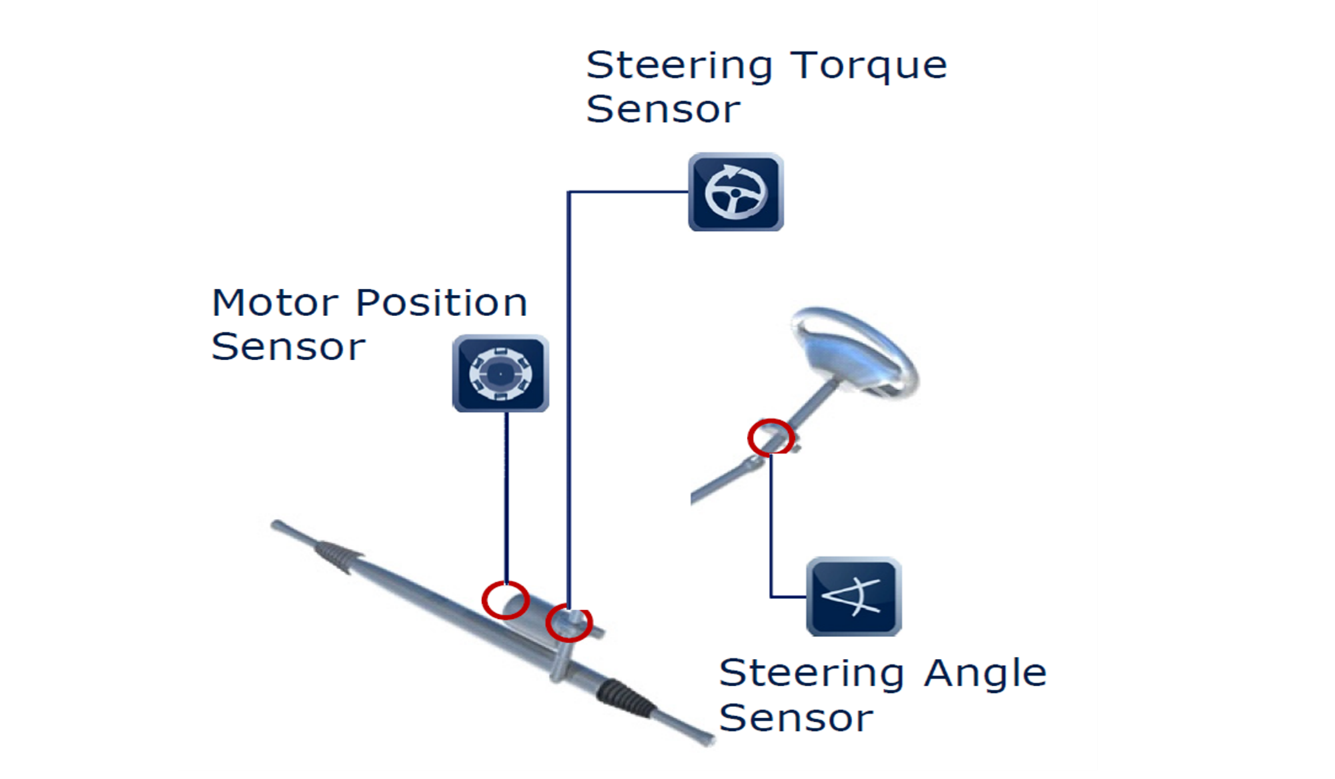
Sensors and their position
A typical EPS includes a set of sensors to read the motor position, the steering angle and the steering torque, as shown in
Figure 5
.
Figure 5. Sensors position
Torque sensor
The steering torque sensor measures the torque exerted on the steering wheel by the driver. Its signal is fed into the ECU and used to regulate the amount of assisting torque provided by the motor. The torque sensor in this example uses a diverse redundancy such that faults can be detected, for example, using an inverse sensing scheme between the two redundant channels. Torque sensors typically communicate with the AURIX™ TC3xx using the SENT protocol.
An example of a torque sensor is the Infineon hall-based magnetic sensor TLE4999C8, designed for torque sensing applications. One of the key functional safety features is the ability to detect and report faults in the sensor output. This can be achieved through a combination of redundant signal processing and built-in self-test mechanisms.
The redundant signal processing ensures that two independent sensing elements are used to generate differential output signals. These signals can then be compared by the MCU, which does a plausibility check to detect any issue in the measurement chain. The built-in self-test mechanisms allow the sensor to periodically test its own internal components and report any errors or faults to the system control unit.
Figure 6. Dual-die hall-based magnetic sensor characteristic
Another important functional safety feature of the sensor is its ability to withstand harsh environmental conditions, such as high temperatures, humidity and vibration. This can be achieved using specialized packaging and sealing techniques, as well as the integration of built-in protection features such as overvoltage and reverse-polarity protection.
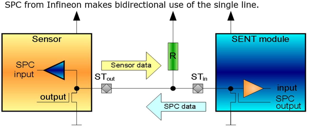
To be easily integrated with other components of the system, such as MCUs and motor drivers, the sensor features a bus-capable digital short-PWM-code (SPC) interface (similar to SENT), which can be easily configured.
Pinout AURIX™ TC3xx to the torque sensor
Figure 7. Infineon TLE4999C8 torque sensor schematic and data example
shows the connection that is needed for functional and safety purposes when using TLE4999C8 as a torque sensor chip. It is necessary to visit the Infineon website to check which is the most appropriate and up-to-date chip before making any decisions about the project.
NR | AURIX™ | Torque sensor | Description |
|---|---|---|---|
1 | SENT | SPC | The two sensor outputs are transmitted using the SPC protocol. |
Figure 8. Sensor communication to AURIX™ TC3xx via SPC protocol
Steering angle sensor (SAS)
The steering angle sensor is typically mounted at the top of the steering column, close to the steering wheel inside the passenger compartment. It is not required for the basic functionality of the EPS system, but it is required for the electronic stability program (ESP), which assists the driver in critical driving conditions. It usually communicates via SENT or SPI to the MCU.
Some of the key safety features for a steering angle sensor in an EPS application are:
Redundancy:
The SAS should have redundant sensor elements and signal processing circuitry to provide reliable operation in case of a single-point failure. This redundancy can ensure that the sensor continues to operate safely and accurately even in the event of a failure in one of the sensor elements.
Diagnostic coverage:
Both internal self-diagnostics and external system-level diagnostics (see below explanation)
Accuracy:
The SAS should provide accurate and reliable position sensing to ensure that the EPS system operates safely and predictably.
Figure 9. Dual-die angle output of the steering angle sensor
For the above use cases, it uses a dual-die implementation, that is, two fully redundant measurement outputs in one package. In this example, for both chip 1 and chip 2, two different SENT connections are present to transmit the angle sensor measurement; one pin of each chip is the interface for channel 1 and a second pin of each chip is the interface for channel 2. For each single chip, the MCU will take care of a plausibility check to ensure that the two measures are coherent. In addition, another plausibility check is performed to evaluate the information coming from the two different chips and correlate it.
Figure 10. Two outputs from two dual-die-angle sensors
Pinout AURIX™ TC3xx to the steering angle sensor
lists an example of connections needed for functional and safety purposes when using the TLE5014D angle sensor chip with SENT configuration. It is necessary to go to the Infineon website to check which is the most appropriate and up-to-date chip before making any decisions about the project.
NR | AURIX™ | Angle sensor | Description |
|---|---|---|---|
1 | SENT 1 | Chip 1 IFB-1 | Input to MCU - SENT/SPC/PWM/SICI interface for channel 1 First redundant sensor |
2 | SENT 2 | Chip 1 IFB-2 | Input to MCU - SENT/SPC/PWM/SICI interface for channel 2 First redundant sensor |
3 | SENT 3 | Chip 2 IFB-1 | Input to MCU - SENT/SPC/PWM/SICI interface for channel 1 Second redundant sensor |
4 | SENT 4 | Chip 2 IFB-2 | Input to MCU - SENT/SPC/PWM/SICI interface for channel 2 Second redundant sensor |
Figure 11. Sensor communication to AURIX™ TC3xx via SENT
Rotor position sensor
The rotor position sensor is mounted directly at the end of the shaft of the EPS motor, which is commonly a highly efficient BLDC motor. It can use multiple analog signals (sin and cos, resolver) or a digital signal (SENT). There are multiple options for sensing the motor position, for example, magnetic sensors, resolvers and encoders.
Figure 12. Infineon TLE5309A16(D) rotor position sensor wiring diagram
Figure 13. Example of a rotor position sensor with redundancy and diversity
One way to sense motor position is to use a sensor that includes two independent sensing elements, with each element providing a single/differential output signal for both the sine and cosine components of the magnetic field. This results in a total of two/four signals, with one/two sets of redundant signals for each component. The redundant single/differential signals for the sine and cosine components provide several benefits for functional safety.
The bottom sensor element is an anisotropic magnetoresistance (AMR) sensor. Therefore, in the angle range of 180° to 360° of the
giant magnetoresistance
(GMR) sensor, the AMR sensor output signal will be in the range of 0° to 180° again. This is represented by the blue line in
Figure 13
.
In case a diverse output of the two sensors is desired, the connections to the SIN_N and SIN_P or COS_N and COS_P pins on the printed circuit board can be interchanged. The consequence of this change of connections is that either the differential sine or the cosine signal is inverted, as represented by the dotted blue line in
Figure 13
.
If differential signaling is used (8 connections instead of 4), this can reduce the effects of electromagnetic interference (EMI) on the signal, which can improve the accuracy and reliability of the sensor. This solution also provides a redundancy feature that can help detect and isolate faults in the signal.
Pinout AURIX™ TC3xx to the rotor position sensor
lists an example of connections needed for functional and safety purposes when using TLE5309A16(D) as a rotor position sensor chip. It is necessary to go to the Infineon website to check which is the most appropriate and up-to-date chip before making any decisions about the project.
The TLE5309A16(D) sensor can be used in single-ended or differential output mode.
Figure 13
shows a typical application circuit for the TLE5309A16(D) in single-ended output mode using the positive output channels. For single-ended operation, positive or negative output channels can be used. Unused single-ended output pins should preferably be floating or connected to GND with a high-ohmic resistance (>100 kΩ). The TLE5309A16(D) contains separate supply pins for the GMR sensor and the AMR sensor.
NR | AURIX™ | Rotor position sensor | Description |
|---|---|---|---|
1 | DSADCX_a | SIN_P1 | Input to cluster X of DSADC |
2 | DSADCX_b | COS_P1 | Input to cluster X of DSADC |
3 | DSADCY_a | SIN_P2 | Input to cluster Y of DSADC |
4 | DSADCY_b | COS_P2 | Input to cluster Y of DSADC |
5 | EVADCZ1.a | VDIAG1 | Input to cluster Z1 of DSADC |
6 | EVADCZ2.b | VDIAG2 | Input to cluster Z2 of DSADC |
Note: To be able to detect any common-cause failure coming from the MCU, it is recommended that X≠Y and Z1≠Z2. In other words, there must be enough independence between the two redundant ADC acquisitions (P1 and P2) and the same is true for the VDIAGx signal. Separation between sin_P1 and sin_P2, cos_P1 and cos_P2, VDIAG1 and VDIAG2 pins also need to be considered, as explained in 1 ..
CAN transceiver
To enable the EPS to interact with the entire car system, an integrated circuit that provides the CAN physical layer is needed. For this reason, a CAN transceiver IC must be selected to enable the AURIX™ TC3xx MCU to communicate using the specific bus protocol.
Some of the key features of a robust CAN transceiver are:
Low current consumption allows the system to accomplish the CAN communication with a small power budget
Fail-safe features such as TxD time-out, RxD recessive clamping (that is, fail-safe feature that prevents sending data on the bus if the RxD line is clamped to high) and overtemperature shut-down allow the system to behave in a predictable manner in safety-critical situations. Other safety measures also report the CAN short circuit proof to ground, battery and VCC, as well as undervoltage detection for the supply voltages
Local failure diagnostics should also be implemented by specifically designed output pins
This IC should be chosen by considering the earlier mentioned characteristics to allow for a safe and reliable communication with the system, as mentioned in
6
.
Figure 14. CAN TLE9252V transceiver pinout
Pinout AURIX™ TC3xx-CAN transceiver
shows the AURIX™ TC3xx-TLE9252V connections.
NR | AURIX™ | CAN | Description |
|---|---|---|---|
1 | _ | CANH | Output of the transceiver to the CAN bus line |
2 | _ | CANL | Output of the transceiver to the CAN bus line |
3 | PORTX1.A1 | NERR | Error flag output, failure and wake-up indication |
4 | PORTX2.A2 | WAKE | Input, sensitive to rising and falling edges |
5 | PORTX3.A3 | NSTB | Standby control input |
6 | _ | INH | Output from external control circuitry—not to be connected to the MCU |
7 | CAN RX | RxD | Receive data output from the MCU |
8 | CAN TX | TxD | Transmit data input from the MCU |
FlexRay communication (optional)
FlexRay is often used instead of CAN in applications where high data transfer rates, deterministic communication and fault tolerance are critical. CAN is a widely used communication protocol in the automotive industry and is suitable for many applications, but it has some limitations that make it less than ideal for safety-critical systems.
One of the key advantages of FlexRay over CAN is its higher data transfer rates. FlexRay supports data transfer rates of up to 10 Mbps, which is significantly faster than the bit rate supported by CAN. This makes FlexRay ideal for applications where large amounts of data need to be transferred quickly and reliably, such as in advanced driver assistance systems (ADAS) and autonomous vehicles.
Another advantage of FlexRay is its deterministic communication. Unlike CAN, which uses a non-deterministic arbitration scheme to resolve conflicts between nodes competing for access to the bus, FlexRay uses a deterministic scheduling scheme that guarantees message transmission times and latencies. This is important for safety-critical systems, where timing is critical and unpredictable latencies can lead to system failures.
FlexRay is also designed to be fault-tolerant, which means that it can continue to operate even if one or more nodes in the network fail. This is important for safety-critical systems, where a single failure can have dangerous consequences.
Some examples of communications in a car that may be implemented using FlexRay instead of CAN include:
Advanced driver assistance systems (ADAS):
FlexRay can be used to transmit sensor data (for example, radar, lidar, camera) to an ADAS control unit for processing and decision-making
Brake-by-wire systems:
FlexRay can be used to transmit signals from the brake pedal to the brake actuator, providing a more responsive and reliable braking system
Electric power steering (EPS) systems:
FlexRay can be used to transmit steering angle and torque data between the EPS control unit and the steering motor, allowing for precise and accurate steering control
Active suspension systems:
FlexRay can be used to transmit data between suspension sensors and the suspension control unit, allowing for real-time adjustment of the suspension system
CAN is still widely used in many automotive applications and is often the preferred choice for simpler, less demanding communication tasks; however, for safety-critical systems or applications that require higher performance, more robust communication and deterministic timing, FlexRay may be a better option.
Summary
It is important highlighting that it is not possible to add safety features in the last phase of the project development; otherwise, it can be that the MCU does not have enough resources in terms of GPIO and peripherals for redundancy. The correct set of safety features needs to be established at the time the MCU is chosen; otherwise, important safety mechanisms can be missing.
This section underlines that the choice of the correct chipset that is used in a safety application requires a good knowledge of application-related risks, safety goals and safety measures required by each specific functionality.
New trends
For automated driving vehicles or for heavy vehicles, the EPS system must be highly available (ISO 26262: safety-related availability). Typically, two EPS systems are used to achieve fail-safe operational steering. These systems individually apply the same safety methods listed above. The two EPS chipsets either operate in parallel or operate in “hot standby” for the second channel.
In case one channel detects an error, it will stop operation (fail silent). However, in contrast to the standard, there are mechanisms installed that automatically detect a fail silent situation on the other channel, such that the remaining channel can take over the full operation and report the situation to higher-level systems, informing the driver.
Figure 15. Transition from Fail-Safe to Fault-Tolerant EPS
References
Infineon Technologies AG:
AURIX™ TC3xx User's Manual
; 81726 Munich; 2021-02; Available online
Infineon Technologies AG:
TriCore™ TC1.6.2 core architecture manual
; Available online
ISO 26262:2018 Road vehicles- Functional safety
; Available online
IEC 61508:2010 Functional safety of electrical/electronic/programmable electronic safety-related systems
; Available online
Infineon Technologies AG:
AN1000 - FuSa in a Nutshell - release note
; Available online
Infineon Technologies AG:
AN1002 - FuSa in a Nutshell - Introduction to AURIX™ TC3xx functional safety
; Available online
Glossary
Definition | Description | Notes |
|---|---|---|
ASC | Active Short Circuit | in the Inverter Use Case |
Architectural Element | The smallest element on which the FMEDA is performed | |
ASIL | Automotive Safety Integrity Level; refer to ISO 26262-1:2018, 3.6 | |
BEV | Battery-powered Electric Vehicle | |
CCF | Common-Cause Failure; refer to ISO 26262-1:2018, 3.18 | |
DC | Diagnostic Coverage; refer to ISO 26262-1:2018, 3.33 | |
DFA | Dependent Failure Analysis identifies single events that can cause multiple sub-parts to malfunction (for example, intended function and its safety mechanism) and lead to a violation of a safety requirement or safety goal. | |
DMI | Data Memory Interface | |
DPF | Dual-Point Failure; for the definition refer to ISO 26262-1:2018, clause 3.38 | |
DSPR | Data Scratch Pad RAM | |
ECU | Electronic Control Unit | |
FHTI | Fault Handling Time Interval is defined in ISO 26262 as the sum of three elements: The fault detection time, the fault reaction time and the time for the system to reach a safe state. | |
FTTI | Fault Tolerant Time Interval; for the definition refer to ISO 26262-1:2018, clause 3.61 | |
FMEA | Failure Mode and Effects Analysis | |
FMEDA | Failure Modes, Effects and Diagnostic Analysis Analysis of the effect of random hardware faults on a safety requirement or safety goal, including quantitative estimation of failure rates and the probability/rate of a safety goal violation | Quantitative Bottom-up HW only |
FTA | Fault Tree Analysis Analysis in which a top-level failure mode is broken down to a combination of lower-level faults (root causes) using a Boolean logic approach | Qualitative (may be quantitative) Top-down HW only |
HARA | Hazard Analysis and Risk Assessment; Refer to ISO 26262-1:2018, 3.76 | |
HW | Hardware | |
IC | Integrated Circuit | |
IEC | International Electrotechnical Commission | |
ISO | International Organization for Standardization | |
LBIST | Logic Built-in Self Test | |
LMU | Local Bus Memory Unit | |
MCU | Microcontroller unit | |
MMIC | Monolithic Microwave Integrated Circuit is a type of integrated circuit (IC) device that operates at microwave frequencies (300 MHz to 300 GHz). These devices typically perform functions such as microwave mixing, power amplification, low-noise amplification and high-frequency switching. | |
PMI | Program Memory Interface | |
PMIC | Power Management ICs (PMICs) | |
PMSM | Permanent Magnet Synchronous Machine (with rare earth material) | Motor type |
PSPR | Program Scratch Pad RAM | |
Safety Flip Flops (SFF’s) | Safety flip-flops are special flip-flops that implement a hardware mechanism capable of detecting bit flips within the protected registers, thus preventing single-point faults. | |
Safety Measure | Activity or technical solution to prevent, detect, control or mitigate systematic and random failures. | |
SBC | system basis chips (SBC) SBCs combine mainly three functionalities in a single device: Power supply, CAN and/or LIN transceivers and supporting features (MCU supervision, SPI interface and so on). This integration makes SBC a potentially better alternative to standalone (discrete) solutions, especially in terms of total solution cost and total area. | |
SE | Soft Error | |
SM | Safety Mechanism: for the definition refer to ISO 26262-1:2018, 3.142 | |
SW | Software | |
SPU | Signal Processing Unit | |
STP | Shoot-Through Protection: Protection typical of an inverter gate driver so that the high side and the low side of the three-phase motor legs cannot be activated simultaneously | |
VCU | Vehicle Control Unit |
Revision history
Document revision | Date | Description of changes |
|---|---|---|
V1.0 | 2024-09-12 | Initial release |
V1.1 | 2025-05-28 | Template update Updated the document title |
1
Even if it is possible to connect IHx_N and ILx to the same MCU pin because the gate driver itself provides the negation of IHx_N with respect to ILx, for better performances, it is preferable to keep IHx_N not connected to ILx so that dead time can be customized.