AN237857 Edge Protect Bootloader for PSOC™ Edge
About this document
Scope and purpose
This document describes the architecture and features of the MCUboot based Edge Protect Bootloader. This document also contains getting started information on how to use the Edge Protect Bootloader and enable features such as firmware update using overwrite and swap mechanisms, encrypted boot mechanism, SRAM loading, and more.
Intended audience
This is an introductory document that guides the user to get started with the Edge Protect Bootloader for PSOC™ Edge device, using ModusToolbox™. This document presumes that the user is familiar with AN237849 Getting Started with PSOC™ Edge Security and AN235935 Getting started with PSOC™ Edge E84 on ModusToolbox™ software .
Introduction
A bootloader is a piece of code that executes at device boot up and is responsible for verifying and launching the user application. Bootloaders also make it possible for a product's firmware to be updated in the field. The bootloader is considered to be a trusted application and has privileges to, authenticate the application image, boot the application from a known location in the memory, and to verify and update applications during a firmware update process.
Edge Protect Bootloader (EPB) is an open-source
MCUboot
library-based bootloader, implementation available for PSOC™ Edge.
MCUboot
defines a common framework for the secured bootloader implementation that enables easy firmware upgrades. For the PSOC™ Edge device, the Edge Protect Bootloader is an optional boot loading stage which provides a mechanism to extend the chain of trust to multiple OEM applications, and supports most of the bootloader features enabled by the
MCUboot
library. Edge Protect Bootloader is designed to run in the secure mode of the CM33 CPU, with all resource access privileges available to it. It is hardened against physical attacks using the
Fault Injection Hardening (FIH)
library, which is also used by open-source
MCUboot
.
Basic boot flow
The boot flow in a PSOC™ Edge device starts from the Secure Enclave, which is the Root of Trust of the device. The Secure Enclave boot authenticates and launches the Extended Boot. Extended Boot is owned by Infineon and it is the first piece of code that will be executed by the CM33 CPU in secure mode. Extended Boot validates the first user application that executes in the CM33 SPE (Secure Processing Environment). While this first application may be any user application that can execute in CM33 SPE, this document assumes the Edge Protect Bootloader (EPB) is the first user application that is launched by Extended Boot .Extended Boot expects application in MCUboot format. Hence, the EPB itself should be in the
MCUboot image format
to be recognized as a valid image by the Extended Boot. In case of secure boot enabled in Extended Boot, the EPB image should be signed for successful verification.
Extended boot is designed to verify a single image in the boot chain. However, in scenarios where multiple images need to be authenticated before the system can safely boot, a more comprehensive approach is required. Edge Protect Bootloader (EPB) is the intermediate boot stage that has the ability to extend the Chain of Trust (CoT) up to 5 images in the boot chain. EPB is capable of validating all the images, and then launching the first image (CM33_S project). The CM33_S project continues to execute in the SPE, and is responsible for applying the security configurations such as TrustZone SAU configurations, MPC/PPC protections and then launching the CM33 NSPE application (CM33_NS project). The CM55 CPU and application can either be started by CM33 Secure or non-secure applications; however, it is typically launched by the latter as is shown in
Figure 1
.
Figure 1.
Boot flow using EPB
Bootloader overview
A portion of the flash memory can be partitioned into multiple image areas, each contains two image slots: a primary slot and a secondary slot. Typically, the primary slot is the area where the image executes from, and the secondary slot is a temporary storage where new upgradable images are downloaded.
The Edge Protect Bootloader application executes in secured mode and is privileged to access the primary slot while a less-privileged applications such as a CM33 non-secure and CM55 applications cannot access the primary slot, but it can access the secondary slot.
The Edge Protect Bootloader (EPB) plays a crucial role in ensuring a safe boot process. Upon bootup, EPB validates the application image in the secondary slot. If the image is valid, EPB proceeds to update the image. If the secondary slot image is invalid, EPB redirects its validation process to the primary slot and launches the application if the image is valid. EPB checks for images in the MCUboot format, providing a basic level of validation. Authentication is an optional feature that requires users to enable the secure boot feature explicitly. In that case, EPB verifies the signature of the application before launching it.
Figure 2.
Bootloader overview
Memory map
The memory map describes allocated memory areas for different application slots and defines their start offsets and sizes. It is defined at compile-time and cannot be changed dynamically.
When the flash memory contains multiple executable images, the flash must be partitioned to allocate two slots for each image.
shows the default memory map used by the EPB compatible simple application such as
Basic Secure App
.
Figure 3.
Example memory map
Note:
Edge Protect Bootloader (EPB) itself may reside in the RRAM or external flash memory. It can also be copied to the internal SRAM memory by the Extended boot and executed from there.
MCUboot image format
Applications that are using the Edge Protect Bootloader (EPB ) must support the
MCUboot
image format or else the EPB will not recognize the image as valid.
Edge Protect Tools
can be used to wrap any application image into a
MCUboot
compatible format.
See
Figure 4
for a representation of the MCUboot image format.
Figure 4.
MCUboot image format
The image header contains basic information about the image binary such as size and versioning information:
#define IMAGE_MAGIC                 0x96f3b83d

#define IMAGE_HEADER_SIZE           32

struct image_version {
    uint8_t iv_major;
    uint8_t iv_minor;
    uint16_t iv_revision;
    uint32_t iv_build_num;
};

/** Image header.  All fields are in little endian byte order. */
struct image_header {
    uint32_t ih_magic;
    uint32_t ih_load_addr;
    uint16_t ih_hdr_size;           /* Size of image header (bytes). */
    uint16_t ih_protect_tlv_size;   /* Size of protected TLV area (bytes). */
    uint32_t ih_img_size;           /* Does not include header. */
    uint32_t ih_flags;              /* IMAGE_F_[...]. */
    struct image_version ih_ver;
    uint32_t _pad1;
};
The original binary image (payload) is suffixed with Type-Length-Value (TLV) pairs. This contains information about how the image was signed and encrypted. Users can also add custom information if there is other metadata they would like to add to an image. Using TLV pairs avoids the need to budget space for features not being used for a particular application and gives the end-user flexibility over the type of information included.
#define IMAGE_TLV_INFO_MAGIC        0x6907
#define IMAGE_TLV_PROT_INFO_MAGIC   0x6908

/** Image TLV header.  All fields in little endian. */
struct image_tlv_info (
    uint16_t it_magic;
    uint16_t it_tlv_tot;  /* size of TLV area (including tlv_info header) */
);

/** Image trailer TLV format. All fields in little endian. */
struct image_tlv (
    uint8_t  it_type;   /* IMAGE_TLV_[...]. */
    uint8_t  _pad;
    uint16_t it_len;    /* Data length (not including TLV header). */
);
/*
 * Image trailer TLV types.
 */
#define IMAGE_TLV_KEYHASH           0x01   /* hash of the public key */
#define IMAGE_TLV_SHA256            0x10   /* SHA256 of image hdr and body */
#define IMAGE_TLV_RSA2048_PSS       0x20   /* RSA2048 of hash output */
#define IMAGE_TLV_ECDSA224          0x21   /* ECDSA of hash output - Not supported anymore */
#define IMAGE_TLV_ECDSA_SIG         0x22   /* ECDSA of hash output */
#define IMAGE_TLV_RSA3072_PSS       0x23   /* RSA3072 of hash output */
#define IMAGE_TLV_ED25519           0x24   /* ED25519 of hash output */
#define IMAGE_TLV_SIG_PURE          0x25   /* If true then any signature found has been
                                              calculated over image directly. */
#define IMAGE_TLV_ENC_RSA2048       0x30   /* Key encrypted with RSA-OAEP-2048 */
#define IMAGE_TLV_ENC_KW            0x31   /* Key encrypted with AES-KW-128 or
                                              256 */
#define IMAGE_TLV_ENC_EC256         0x32   /* Key encrypted with ECIES-P256 */
#define IMAGE_TLV_ENC_X25519        0x33   /* Key encrypted with ECIES-X25519 */
#define IMAGE_TLV_DEPENDENCY        0x40   /* Image depends on other image */
#define IMAGE_TLV_SEC_CNT           0x50   /* security counter */
For the firmware update use-case, the metadata about the staged image, whether or not to perform an upgrade is tracked in the “Image Trailer”. This information is located at the end of each “slot” in use and looks like this:
 0                   1                   2                   3
     0 1 2 3 4 5 6 7 8 9 0 1 2 3 4 5 6 7 8 9 0 1 2 3 4 5 6 7 8 9 0 1
    +-+-+-+-+-+-+-+-+-+-+-+-+-+-+-+-+-+-+-+-+-+-+-+-+-+-+-+-+-+-+-+-+
    ~                                                               ~
    ~    Swap status (BOOT_MAX_IMG_SECTORS * min-write-size * 3)    ~
    ~                                                               ~
    +-+-+-+-+-+-+-+-+-+-+-+-+-+-+-+-+-+-+-+-+-+-+-+-+-+-+-+-+-+-+-+-+
    |                 Encryption key 0 (16 octets) [*]              |
    |                                                               |
    +-+-+-+-+-+-+-+-+-+-+-+-+-+-+-+-+-+-+-+-+-+-+-+-+-+-+-+-+-+-+-+-+
    |                    0xff padding as needed                     |
    |  (BOOT_MAX_ALIGN minus 16 octets from Encryption key 0) [*]   |
    +-+-+-+-+-+-+-+-+-+-+-+-+-+-+-+-+-+-+-+-+-+-+-+-+-+-+-+-+-+-+-+-+
    |                 Encryption key 1 (16 octets) [*]              |
    |                                                               |
    +-+-+-+-+-+-+-+-+-+-+-+-+-+-+-+-+-+-+-+-+-+-+-+-+-+-+-+-+-+-+-+-+
    |                    0xff padding as needed                     |
    |  (BOOT_MAX_ALIGN minus 16 octets from Encryption key 1) [*]   |
    +-+-+-+-+-+-+-+-+-+-+-+-+-+-+-+-+-+-+-+-+-+-+-+-+-+-+-+-+-+-+-+-+
    |                      Swap size (4 octets)                     |
    +-+-+-+-+-+-+-+-+-+-+-+-+-+-+-+-+-+-+-+-+-+-+-+-+-+-+-+-+-+-+-+-+
    |                    0xff padding as needed                     |
    |        (BOOT_MAX_ALIGN minus 4 octets from Swap size)         |
    +-+-+-+-+-+-+-+-+-+-+-+-+-+-+-+-+-+-+-+-+-+-+-+-+-+-+-+-+-+-+-+-+
    |   Swap info   |  0xff padding (BOOT_MAX_ALIGN minus 1 octet)  |
    +-+-+-+-+-+-+-+-+-+-+-+-+-+-+-+-+-+-+-+-+-+-+-+-+-+-+-+-+-+-+-+-+
    |   Copy done   |  0xff padding (BOOT_MAX_ALIGN minus 1 octet)  |
    +-+-+-+-+-+-+-+-+-+-+-+-+-+-+-+-+-+-+-+-+-+-+-+-+-+-+-+-+-+-+-+-+
    |   Image OK    |  0xff padding (BOOT_MAX_ALIGN minus 1 octet)  |
    +-+-+-+-+-+-+-+-+-+-+-+-+-+-+-+-+-+-+-+-+-+-+-+-+-+-+-+-+-+-+-+-+
    |                    0xff padding as needed                     |
    |         (BOOT_MAX_ALIGN minus 16 octets from MAGIC)           |
    +-+-+-+-+-+-+-+-+-+-+-+-+-+-+-+-+-+-+-+-+-+-+-+-+-+-+-+-+-+-+-+-+
    |                       MAGIC (16 octets)                       |
    |                                                               |
    +-+-+-+-+-+-+-+-+-+-+-+-+-+-+-+-+-+-+-+-+-+-+-+-+-+-+-+-+-+-+-+-+
Note:
Adding EPB to ModusToolbox™code examples
The ModusToolbox™
Edge Protect Bootloader
is available as a code example and can be used together with any other PSOC™ Edge code example. It consists of the
proj_bootloader
directory which contains the bootloader application. This bootloader application depends on the
ifx-mcuboot-pse84
library, and supports the
Edge Protect Bootloader
solution personality of the device configurator.
The steps below demonstrate how to add the
proj-bootloader
to the
Hello World
code example. The same steps may be followed to add it other code examples.
Note:
Some code examples such as
Basic Secure App
have preconfigured bootloader personality for default use cases, and hence the user need not perform the steps (7-13) required for configuring the bootloader personality. Such code examples will contain reference to the Edge Protect Bootloader compatibilty in their README.md file.
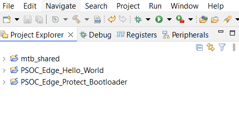
Create two applications -
Hello World
and
Edge Protect bootloader
in your workspace
Figure 5.
Create two applications
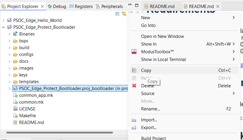
In the MTB Project Explorer, right click on
PSOC_Edge_Protect_Bootloader.proj_bootloader
and copy it
Figure 6.
Copy proj_bootloader
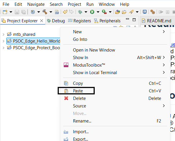
Paste it to the root of
Hello world
as shown below
Figure 7.
Paste the proj_bootloader to application folder
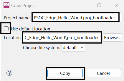
While pasting you need to rename the project as
<application-name>.proj_bootloader
and provide the absolute path to proj_bootloader such as
<application-path>\proj_bootloader
Figure 8.
Rename the proj_bootloader while pasting
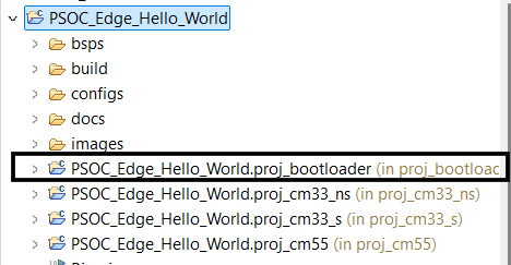
Bootloader project is now copied to Hello World application
Figure 9.
Hello World with bootloader
Open the
Makefile
in the root of the Hello World application and add
proj_bootloader
to list of
MTB_PROJECTS
as shown below
MTB_PROJECTS=proj_cm33_s proj_cm33_ns proj_cm55 proj_bootloader
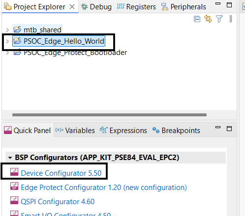
Now click on the
PSOC_Edge_Hello_World
in
Project Explorer
and open the Device Configurator from the
Quick Panel
to configure the Edge Protect Bootloader solution (Steps 7-13 may be skipped for pre-configured code examples)
Figure 10.
Open Device Configurator
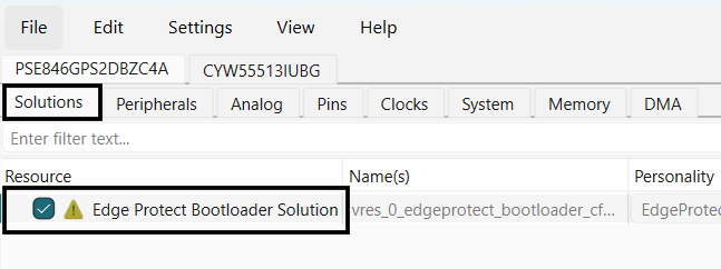
In the Device configurator window, enable the
Edge Protect Bootloader solution
under the
Solutions
tab
Figure 11.
Enable Edge Protect Bootloader solution
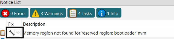
Click on the
fix
for bootloader_nvm region not found, to add a memory region for bootloader
Figure 12.
Add bootloader_nvm region
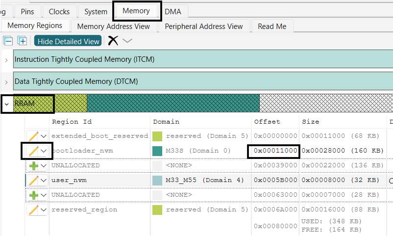
In the
Memory
tab of the Device configurator, edit the
bootloader_nvm
region in the
RRAM
memory to start from 0x00011000 offset. Adjust other user nvm region offset accordingly
Figure 13.
Edit bootloader_nvm region
Note:
Bootloader in RRAM is the default configuration. Bootloader can also be placed in the External flash region. See
Bootloader in external flash memory
Add new secondary slot regions in the external flash memory for all three projects as shown below
Figure 14.
Add secondary slot regions in external flash
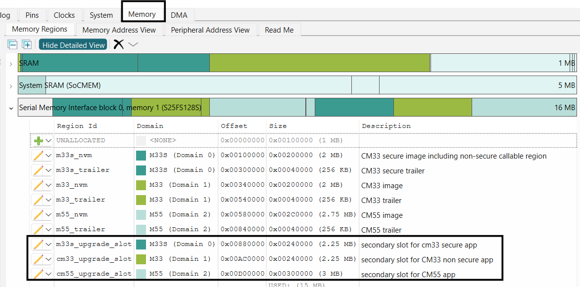
Note:
Primary and secondary slot region sizes must be same
Now go back to the
Solutions
tab and configure each application project in Bootloader solution personality for primary and secondary slot regions
Figure 15.
Configure primary and secondary slots
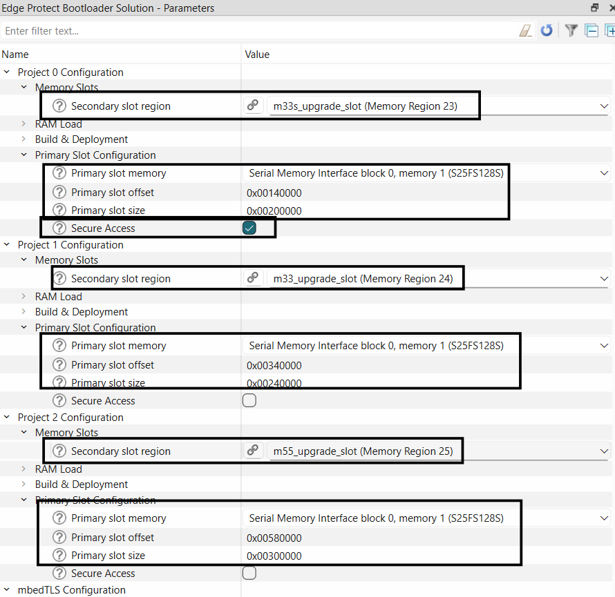
Note:
Primary slot size and start offset need to be configured manually in the bootloader solution personality
The slot sizes and start offsets must be aligned with the slots configured in
Memory
tab of the Device Configurator
The Primary slot size mentioned in the bootloader solution personality is combined size of image + trailer region defied in
Memory
tab
Select secure access for Project 0 primary slot (proj_cm33_s)
Now save your configuration. The
Save
action in the Device Configurator generates configuration files for the bootloader in accordance with
Edge Protect Bootloader
solution. After saving you may close the Device configurator
Open
common.mk
file in the root of the application and update
COMBINE_SIGN_JSON
value to
boot_with_bldr.json
generated by the configurator and save the file.
COMBINE_SIGN_JSON?=./bsps/TARGET_$(TARGET)/config/GeneratedSource/boot_with_bldr.json
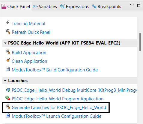
Next, in the MTB IDE, generate launches for your application as shown below. Alternatively, you can execute a
make eclipse/make vscode
in the terminal to re-generate the launch configurations
Figure 16.
Generate launches
Compile and program the Hello world application
Note:
Since the bootloader is programmed to RRAM, the
BOOT SW
on your EVK must be in the "LOW/OFF" position for the application to boot.
Bootloader Features
Image validation
EPB verifies the image in the primary slot (integrity and security check) or at least performs a basic sanity test to avoid booting into an empty flash region. During firmware upgrade, the upgrade image is validated before being copied into the primary slot.
During the
normal boot
, EPB performs an integrity check, by verifying the following aspects of an image:
32-bit magic number must be correct (
IMAGE_MAGIC
)
Image must contain an
image_tlv_info
struct, identified by its magic (
IMAGE_TLV_PROT_INFO_MAGIC
or
IMAGE_TLV_INFO_MAGIC
) exactly following the firmware (
hdr_size
img_size
). If
IMAGE_TLV_PROT_INFO_MAGIC
is found then after
ih_protect_tlv_size
bytes, another
image_tlv_info
with magic equal to
IMAGE_TLV_INFO_MAGIC
must be present
Image must contain an SHA256 TLV
Calculated SHA256 must match SHA256 TLV contents
When
secure boot
is enabled in the EPB, it performs additional signature verification of the images:
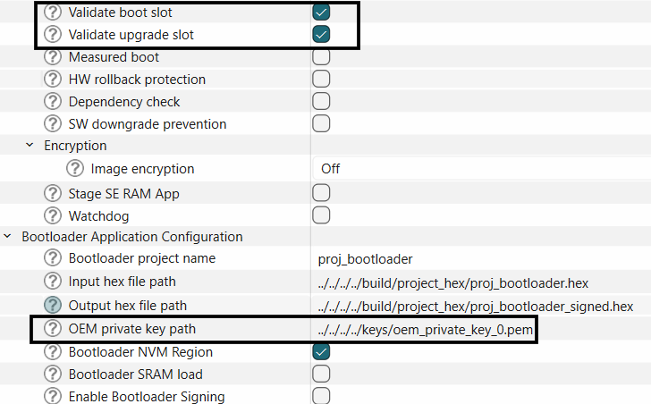
The bootloader verifies that an image was signed with a private key that corresponds to the embedded KEYHASH TLV. The bootloader can have one or more public keys embedded in it at build time
Secure boot in EPB can be enabled by enabling the "Validate boot slot" and "Validate upgrade slot" options in the bootloader solution. Provide the path to the OEM private key to be used to sign the application.
Note:
The private key used for signing should correspond to the OEM key provisioned into the device. See
AN237849 Getting Started with PSOC™ Edge Security
for more information on provisioning.
Figure 17.
Enable image validation for secure boot
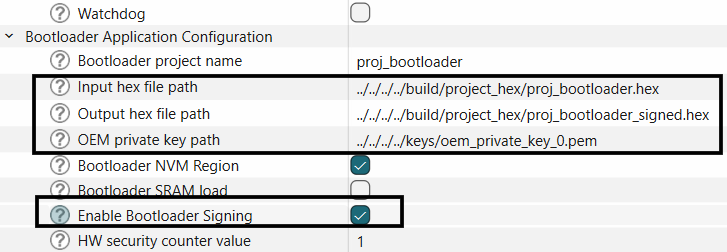
To enable the full secure boot chain, the EPB image itself should be signed, enable this option by selecting the "Enable Bootloader Signing" option in the bootloader solution.
Figure 18.
Enable signing of bootloader image
Save your configuration and close the device configurator.
Use the bootloader generated combiner signer file in the common.mk file (available in the root of the application directory).
COMBINE_SIGN_JSON?=./bsps/TARGET_$(TARGET)/config/GeneratedSource/boot_with_bldr.json
Note: To enable secure boot by the Extended boot, secure boot must be enabled in the OEM policy file and the OEM_ROT_KEY must be provisioned into the device. See
Enable secure boot by Extended Boot
section of the
AN237849 Getting Started with PSOC™ Edge Security
for more details.
Image upgrade
The bootloader supports two different image upgrade methods:
Upgrade by overwrite
Upgrade by swap
Either of these methods can be configured at compile time and the compiled bootloader will only support the selected upgrade method.
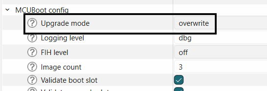
Upgrade by overwrite
This upgrade method implies direct copying of data from the secondary slot of an image to the primary slot area after validation. Thus, any earlier firmware version which was working on the device prior to the update is not preserved and it is not possible to revert the upgrade.
Figure 19.
Upgrade by overwrite
This is the default upgrade mode selected by the bootloader solution, and can be configured as shown below.
Figure 20.
Select the overwrite upgrade mode
The upgrade slots must be allocated and linked in the bootloader solution as described in
Adding EPB to ModusToolbox™ code examples
.
The upgrade image should be compiled by using the "boot_with_bldr_upgr.json" generated by the bootloader solution. Make this change in the common.mk file found at the root of your application.
COMBINE_SIGN_JSON?=./bsps/TARGET_$(TARGET)/config/GeneratedSource/boot_with_bldr_upgr.json
Upgrade by swap
In a swap-based upgrade, the images are swapped between the two slots (primary and secondary) and rollback is possible in case of faulty upgraded image.
In swap mode, the content of the primary slot is copied into the secondary slot, and at the same time the content of the secondary slot is copied into the primary slot. Doing so, both versions of the application are preserved on the device until the upgraded firmware swapped to the primary slot confirms it is operational. EPB initiates the revert procedure and rollback to the previous firmware to the primary slot if the upgraded image is faulty and does not boot.
In this process, the bootloader performs a “test” swap of image first and boots to the upgrade image. The new image can then mark itself as “OK”. When this happens, the swap is made “permanent”. If this does not happen, the bootloader will perform a “revert” swap during the next boot by swapping the image(s) back into its original location(s), and attempting to boot the old image(s).
Image OK
is a single byte in the image trailer indicating whether the image in this slot has been confirmed as good by the user (0x01=confirmed; 0xff=not confirmed). See more details at
MCUboot
.
EPB uses a swap scratch region for swapping the contents between primary and secondary slot, and a swap status region in RRAM for saving the status.
Figure 21.
Swap upgrade
The following sections describe how to enable swap upgrade mode in EPB,
The upgrade slots must be allocated and linked in the bootloader solution as described in
Adding EPB to ModusToolbox™ code examples
Create new memory regions for swap_status and swap_scratch region as shown below:
Figure 22.
Add swap_status and swap_scratch
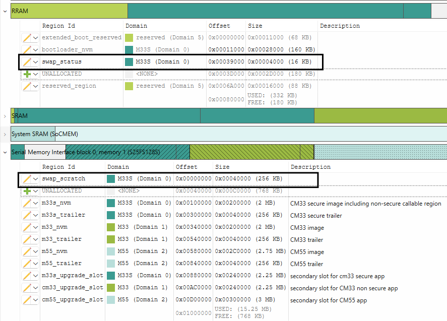
Note:
The swap_status region must be in RRAM. The swap_scratch region is recommended to be in the external flash and must be at least 1 erase sector size
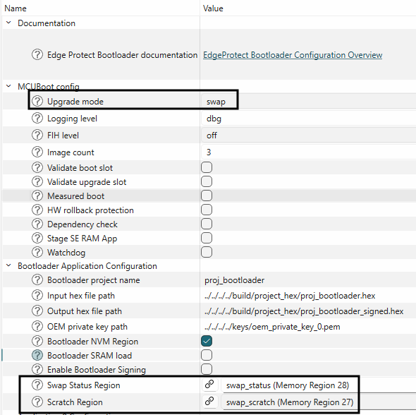
Select the upgrade mode as swap in the bootloader solution and link the swap status and scratch regions as shown in Figure 22
Figure 23.
Configure swap mode
The upgrade image should be compiled by using the "boot_with_bldr_upgr.json" generated by the bootloader solution:
COMBINE_SIGN_JSON?=./bsps/TARGET_$(TARGET)/config/GeneratedSource/boot_with_bldr_upgr.json
See
BTSTACK OTA
code example for a demonstration of firmware update using swap mode.
Downgrade prevention
Downgrade prevention is a feature which ensures that only firmware with a higher version or security counter can replace an existing image. This safeguards against malicious attempts to revert the device to a potentially vulnerable older version.
There are two types of downgrade preventions.
Software-based downgrade prevention
Hardware-based downgrade prevention
Software based downgrade prevention
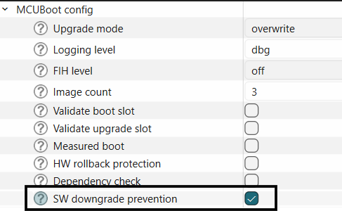
Software-based downgrade prevention compares image version numbers to block installations of older firmware. This feature works exclusively with the overwrite-based image update strategy.
This feature may be enabled in the bootloader solution as shown below.
Figure 24.
Enable software downgrade prevention
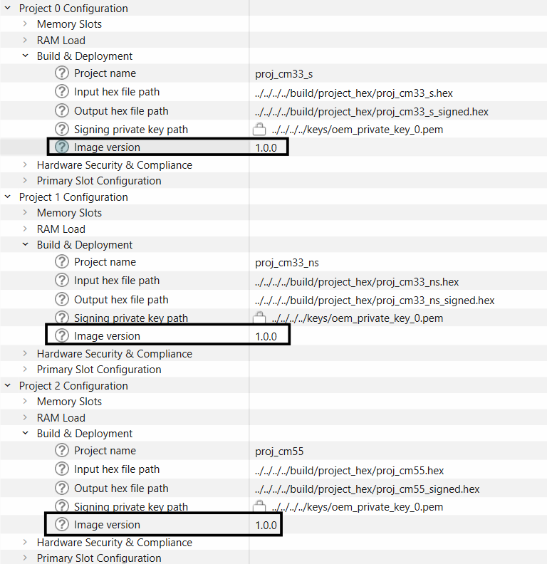
Also, set the image versions for each application image as shown below.
Figure 25.
Set image versions
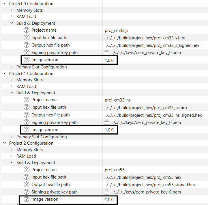
When this feature is enabled, EPB will reject the firmware update if the update image contains a lower major/minor/patch version. For example, if the current image version is 1.2.3 and the update image contains version 1.2.2, the firmware update will be rejected.
If there are multiple images and only some images are getting updated, you can set the image version dependency of one image on another image. See more details in
Dependency check
.
Hardware based downgrade prevention
Each signed image can contain a security counter in its protected TLV area, which can be added to the image using the
-s
option of the Edge Protect Tools sign command. During the hardware-based downgrade prevention (rollback protection) the new image’s security counter value will be compared with the currently active security counter which is stored in the Secure Enclave. It is beneficial to handle this counter independently from the image version number due to the following reasons,
No need to increase this counter value with each software release.
Allows for software downgrades to a limited extent: an older image will be accepted if its security counter matches the current value.
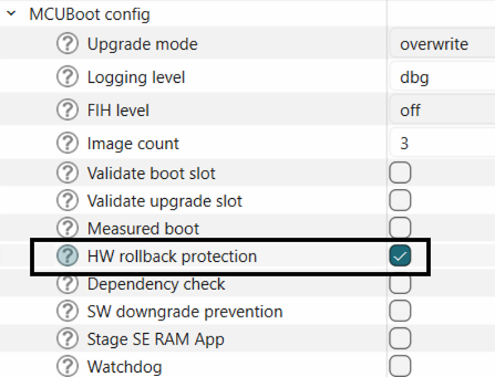
This feature can be enabled in the bootloader solution as shown below:
Figure 26.
Enable HW rollback protection
Set
HW security counter number
and
HW security counter value
.
HW security counter number
refers to the number of the counter cell in the device. It can be set in the range of 2-7, or used as is. The security counter number 1 is always used for the EPB image.
HW security counter value
refers to the counter value that is stored in the counter. It can be set in the range of 1-63 or left unchanged. Writing a value to this counter is an irreversible operation. You can only add new counter values (until 63). Care must be taken during the firmware update to not to exceed this counter range, else future firmwares updates will fail.
Figure 27.
Configure rollback protection
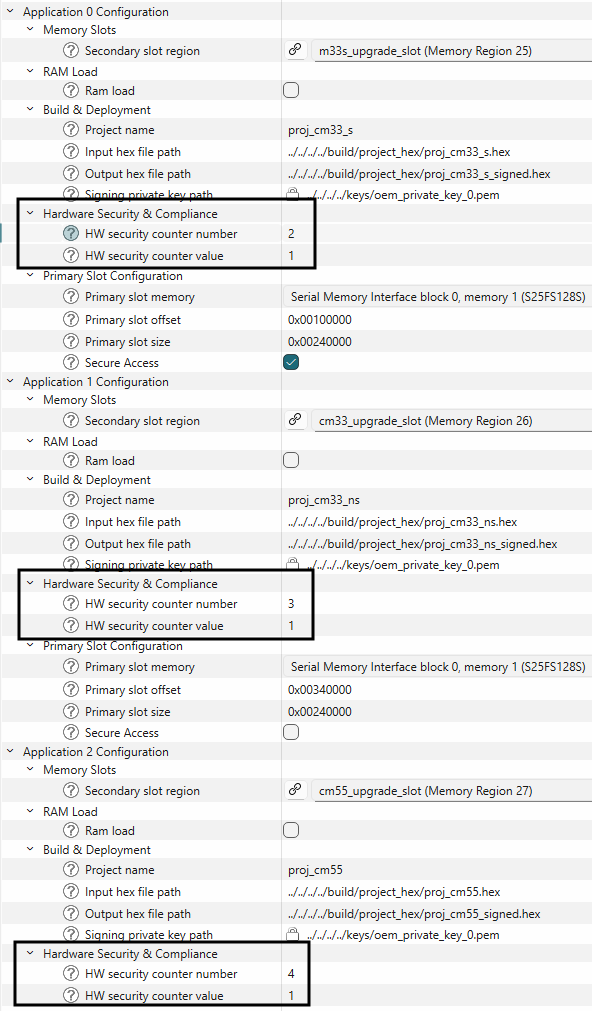
Application images can either use the same counter number or a separate counters. If the same counter is used for all images, all the image upgrades are tightly coupled to this single counter and you will be unable to update a single image with new counter values. If the counter value has to be changed, then all images must be updated.
Alternatively, you can allocate one counter per image and update images independently.
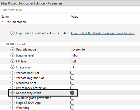
Dependency check
To ensure API compliance and to avoid interoperability issues, the bootloader performs dependency checks and rejects the incompatible updates. This is a highly useful feature when there are more than one executable applications in the flash, and only one of the application images is being updated. In such as scenario, this feature helps in preventing the upgrade of incompatible images.
This feature can be enabled in the Edge Protect Bootloader solution as shown below.
Figure 28.
Enable dependency check
For
each
image, set the image version using the following format: "major", "minor", "patch".
Figure 29.
Add image versions
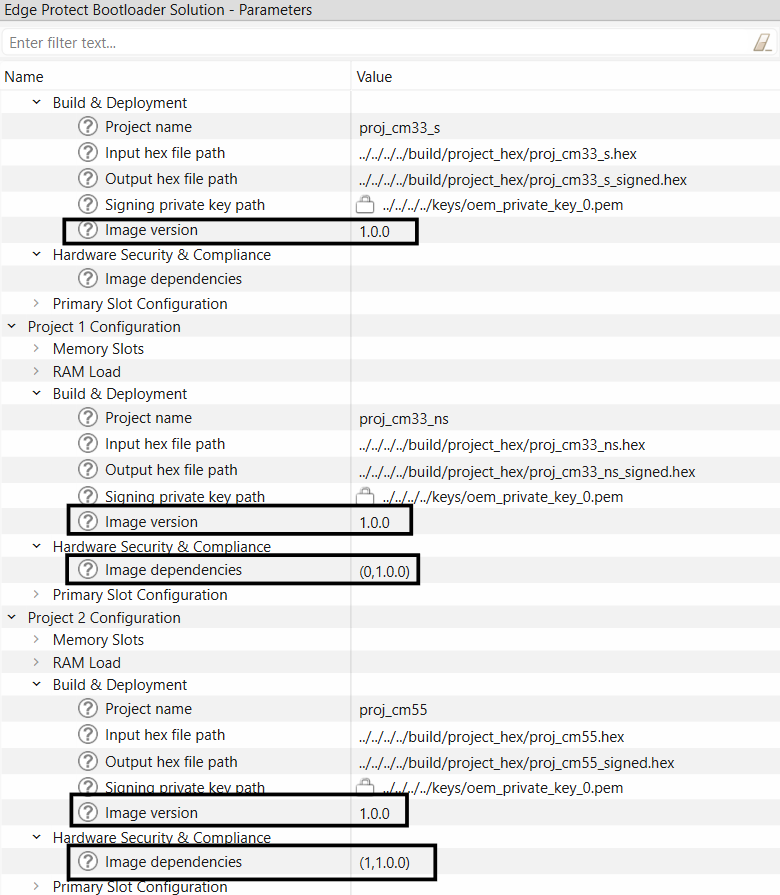
Set image dependencies in the format: (image_ID, image_version) where the image_ID on which this image depends. It starts from 0. image_version version on which this image depends. One image can depend on the several other images such as (1, 1.1.0), (2, 2.0.0).
Figure 30.
Set image dependencies
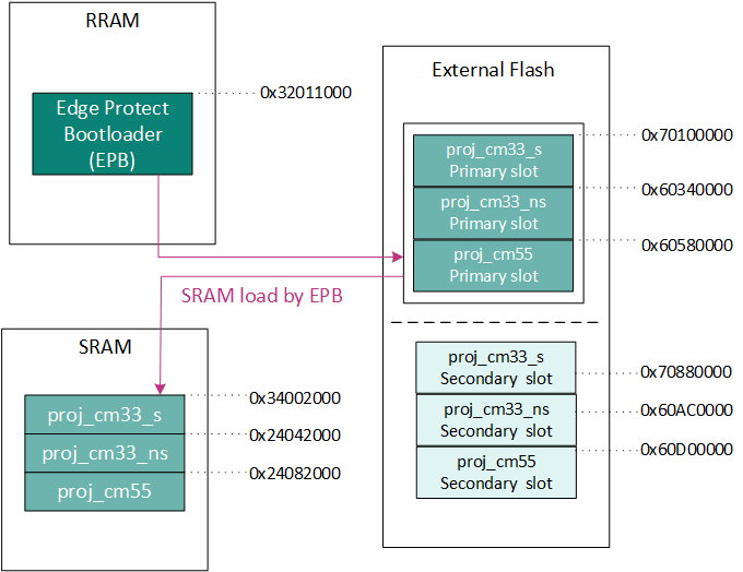
SRAM loading by EPB
Execution of user application from the external flash has some drawbacks such as lower execution speed, higher power consumption and so on, when compared to execution from internal RAM. Bootloader supports the "RAM loading" of application for execution from internal RAM memory. In this case, the application images are programmed to persistent external flash memory, but copied into the internal RAM before execution.
Figure 31.
SRAM Loading by EPB
SRAM loading by EPB can be enabled in the bootloader solution as shown below.
Figure 32.
Enable SRAM loading by EPB
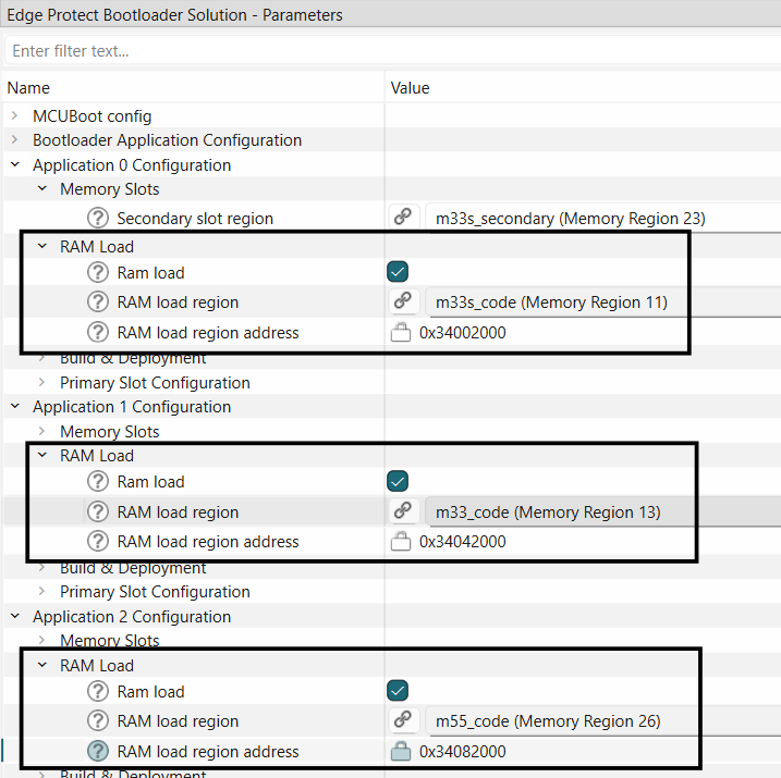
The RAM loading feature requires that the application image is compiled to be executed from the internal RAM address range instead of the external flash region, and using Edge Protect Tools the compiled hex file can be signed such that the image will programmed into the external flash region. While signing the image, a "load-address" parameter is required, which contains the address in the SRAM where the application should be copied to before the execution and the "hex-address" parameter indicates the address in NVM memory where the image will reside. An example of the configuration that is generated for this feature is as shown below
"command" : "sign",
                    "inputs" :
                    [
                        (
                            "file" : "../../../../build/project_hex/proj_cm33_s.hex",
                            "header-size": "0x400",
                            "fill-value" : "0xFF",
                            "slot-size" : "0x00240000",
                            "overwrite-only" : true,
                            "load-address" : "0x34002000",
                            "hex-address" : "0x70100000"
                        )
                    ],
                    "outputs":
                    [
                        (
                            "file" : "../../../../build/project_hex/proj_cm33_s_signed.hex",
                            "format": "ihex"
                        )
                    ]
Refer to
PSOC™ Edge SRAM Loading
code example for a demonstration of SRAM loading by EPB.
Note:
The default EPB can be used to load applications to the SRAM region and execute from there. EPB maybe customized by the user to load applications into System SRAM or ITCM regions.
Encryption support
Firmware image may be encrypted and programmed into the device memory. Edge Protect Bootloader supports the encrypted firmware when EPB runs from RRAM only. Encrypted user images must be located in the external flash memory and executed in SMIF XIP mode or decrypted and loaded to SRAM for execution.
Edge Protect Bootloader supports the execution of the encrypted application in the following different methods.
Single key encryption (EPC 2)
Multi key encryption (EPC 2)
Secure encryption (EPC 4)
Single Key XIP Encryption (EPC 2)
In the single key encryption method, all the three application images are encrypted with the same AES encryption key. The first application image also contains this AES encryption key and AES nonce (it is a part of the initial vector) packed to the HKDF block and stored in one of TLV in the image. For this first image, only the payload (application code part) is encrypted. The header and TLV are stored as plain data. The second and the next images are encrypted from start to end by the same (including header and TLVs) AES key and AES nonce as payload of the first image. These images are always handled by the Edge Protect Bootloader as non-encrypted.
An ECC key pair (Key Encryption Key) is used to encrypt the encryption key, the private portion of this Key Encryption Key must be stored at a location accessible to EPB. For the default configuration, it must be stored in the RRAM (0x3203A000)
At device boot up, Edge Protect Bootloader detects that the first image is an encrypted application with HKDF block, decodes the AES key and AES nonce from the HKDF block, initializes SMIF XIP hardware encryption block with this key and nonce values, and validates the image. If the first image is valid, then the Edge Protect Bootloader turns on SMIF XIP hardware encryption with AES key and AES nonce from the first image and validates the next images with “on the fly” SMIF XIP hardware decryption.
Note:
This method is only supported with overwrite upgrade mode.
Figure 33.
Single key encryption
For demonstration on how to use the single key encryption, refer to the
Encrypted boot
code example.
Multi Key XIP Encryption (EPC 2)
Multi key SMIF XIP encryption with up to 4 different encrypted areas and different AES keys is supported by the Edge Protect Bootloader for PSOC™ Edge device. The SMIF IP block of the PSOC™ Edge has 4 SMIF crypto blocks that allows to use up to 4 different encrypted areas. Each SMIF crypto block can have its own AES key and nonce (random number). Each image always contains its own AES key and AES nonce (it is a part of the initial vector) packed to HKDF block and stored in one of TLV in the image. In this method, the image payload (application code part) is encrypted only. The header and image TLV are stored as plain data.
An ECC key pair (Key Encryption Key) is used to encrypt the encryption key, the private portion of this Key Encryption Key must be stored at a location accessible to EPB. For the default configuration, it must be stored in the RRAM (0x3203A000)
This method is supported with both overwrite and swap upgrade modes.
During the boot, if the Edge Protect Bootloader detects that the image is encrypted with HKDF block, it decodes the AES key and AES nonce from the HKDF block, and then initializes the SMIF XIP hardware encryption block with the corresponding key and nonce, and validates this image. During the image validation, the Edge Protect Bootloader decrypts payload data via offline SMIF decryption using the SMIF crypto block. The image header and TLVs are read as plain date. After validation of all images, the Edge Protect Bootloader applies the AES key and the AES nonce for the appropriate SMIF crypto block (the number of the crypto block is equal to "image number - 1"). The size of encrypted area handled by the current crypto block is equal to the image slot size.
Note:
Multi key XIP encryption has strict requirements for encryption region size and start address. The slot size of the application must be a perfect power-of-two number. The start address of the application image must be a multiple of its slot size, i.e., start_address = N * size.
Figure 34.
Multi key encryption
The following section describes how to enable multi key encryption for a ModusToolbox™ code example. As a pre-requesite, provision the device to enable secure boot as described in
AN237849 Getting Started with PSOC™ Edge Security
After following the steps for
Adding EPB to ModusToolbox™ code examples
, perform the steps below to use multi key encryption in your code example.
Enable image validation as described in
Image validation
section
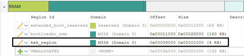
Create a region for the private portion of key encryption key (kek_region) in RRAM
Figure 35.
Add region for KEK in RRAM
Generate an ECC key pair in the PEM format using edgeprotecttools
edgeprotecttools create-key --key-type ECDSA-P256 --output keys/enc-ec256-priv.pem keys/enc-ec256-pub.pem
Convert the PEM private key to DER-PKCS8 format and store in a bin file
edgeprotecttools convert-key -k keys/enc-ec256-priv.pem -o keys/enc-ec256-priv.bin -f DER-PKCS8
Program private key to the device by using programming tools at the start address of the "kek_region"
<openocd-install-path>/openocd.exe -s scripts -f interface/kitprog3.cfg -f target/infineon/pse84xgxs2.cfg -c "init; reset init; flash write_image keys/enc-ec256-priv.bin <kek_region_start address>; reset; shutdown"
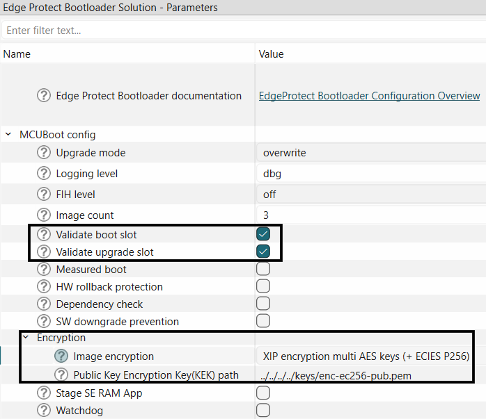
Set the encryption mode to
XIP encryption multi AES keys (+ ECIES P256)
Figure 36.
Enable multi key encryption
Generate AES key for each image using edgeprotecttools
edgeprotecttools create-key --key-type AES128 --output keys/gen_aes_key.bin
Set AES128 key path for each image
Figure 37.
Set encryption key path
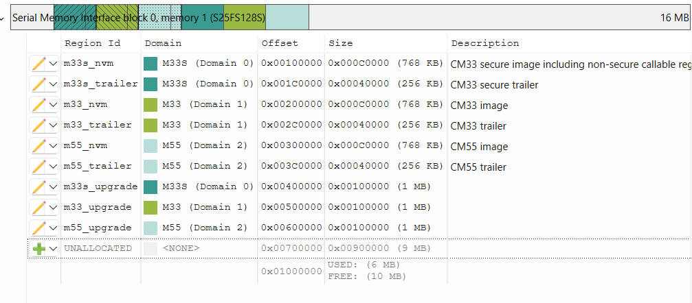
To meet strict size and start addess requirements of this method, the applications memory regions may be updated. In the example below all upgrade images have size = 0x100000
Figure 38.
Memory map for multi key encryption
Secure Encryption (EPC 4)
On EPC 4 devices, a software key based encryption mechanism is supported which is compliant with the PSA L4 certification requirement. For this use case, the private portion of the Key Encryption Key (KEK) must be provisioned into the device using the "user keys" section of the OEM policy file. This method uses the AES CMAC algorithm for encryption.
This flow can only be used when the images are loaded into SRAM and executed from there.
Note:
The secure Enclave cipher key allows only 100000 encrypt/decrypt operations, as a result the image size is limited to 1.6 MB.
The following section describes how to enable secure encryption.
Use the
SRAM loading
code example for the demonstration of this feature. Follow the instructions in the README.md file to create and add the bootloader project
Enable image validation as described in
Image validation
section
Generate the key encryption key using
edgeprotecttools create-key --key-type ECDSA-P256 --output keys/enc-ec256-priv.pem keys/enc-ec256-pub.pem
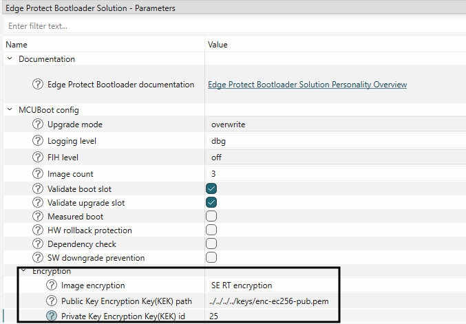
Enable encryption mode
SE RT encryption
in the bootloader solution as shown below. Provide the KEK path and Key ID in decimal
Figure 39.
Enable secure encryption
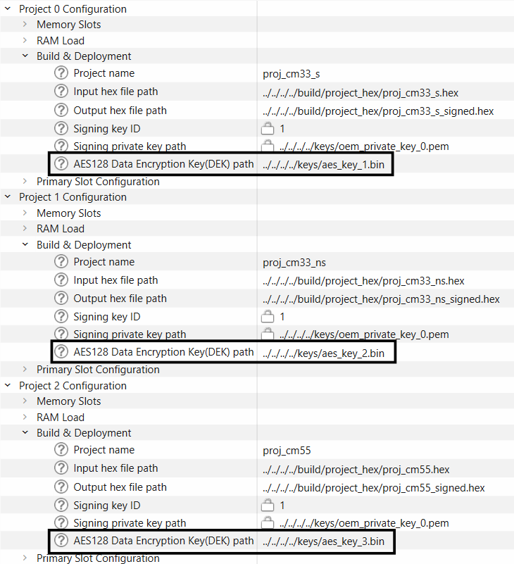
Generate the AES keys for each image using edgeprotecttools
edgeprotecttools create-key --key-type AES128 --output keys/aes_key.bin
Set the AES128 key paths for each image as shown below
Figure 40.
Set encryption key path
Provision the device with private portion of the KEK in provisioning policy. The key information must be included in the user_keys section of the OEM policy as shown below
(
    "kid": (
      "description": "The ID of the key in the PSA vault. The value between '0x40000000' and '0x7FFEFFFF'",
      "value": "0x40000019"
    ),
    "alg": (
      "description": "Key algorithm",
      "applicable_conf": "ECDSA, RSA, AES-CTR, AES-CBC, AES-ECB, ECDH, HKDF_ALG_SHA_256, NONE",
      "value": "ECDH"
    ),
    "use": (
      "description": "Key usage flags are encoded in a bitmask (usage example SIGN|ENCRYPT)",
      "applicable_conf": "EXPORT, COPY, CACHE, ENCRYPT, DECRYPT, SIGN_MESSAGE, VERIFY_MESSAGE, SIGN_HASH, VERIFY_HASH, DERIVE, VERIFY_DERIVATION",
      "value": "DERIVE"
    ),
    "key": (
      "description": "Path to the key file in PEM, DER, or JWK format",
      "value": "../keys/enc-ec256-priv.pem"
    ),
    "owner": (
      "description": "Key owner identifier. The value between '-2147483648' and '2147483647'",
      "value": 0
    )
)
where:
kid
value contains
key_id
equal to
0x40000000 +
ecdh_key_id
alg
value should be set to
ECDH
use
value should be set to
DERIVE
key
value should contain path to the private key
owner
value should be set to
0
Provision the device with the updated policy
edgeprotecttools -t pse8xs4 provision-device --policy policy/policy_oem_provisioning.json --key keys/OEM_ROT_0_PRIV.pemNote:
As a pre-requisite, device ownership must be transferred via provisioning, refer to
AN237849 Getting Started with PSOC™ Edge Security
Measured boot and data sharing
MCUBoot defines a mechanism for sharing boot status information (also known as measured boot) and an interface for sharing application specific information with the run-time software. If any of these are enabled, the target must provide a shared data area between the bootloader and run-time firmware. In the shared memory area, all data entries are stored in a type-length-value (TLV) format. Before adding the first data entry, the whole area is overwritten with zeros and a TLV header is added at the beginning of the area during an initialization phase.
The device might need to prove the integrity of its software to a remote party or to local systems on the same board. A prerequisite for attesting the platform state is to create measurements of loaded code and data on each boot. The measurements are then securely stored either in the trusted firmware or a security subsystem. Any measured boot mechanism must assure the integrity of such firmware and make it part of an overall chain of trust. A remote party or local application may use the list of measurements to help validate the specific software identity of the platform.
When the measured boot configuration is enabled, the "--boot-record" argument must be used during the Edge Protect Tools image signing process. This argument adds a BOOT_RECORD TLV to the image manifest. The TLV consists of the following information about the image in CBOR encoded format.
Software type (role of the software component)
Software version
Signer ID (identifies the signing authority)
Measurement value (hash of the image)
Measurement type (algorithm used to calculate the measurement value)
The "sw_type" string that is been passed as the "--boot-record" option's parameter will be the value of the "Software type" attribute in the generated BOOT_RECORD TLV.
Measured boot and data sharing feature by the bootloader is used by other components such as Trusted Firmware-M for attestation services.
For more information about this topic, see
MCUboot documentation
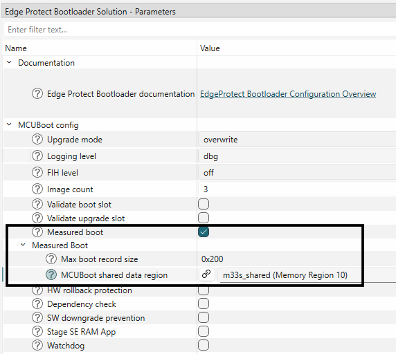
Measured boot may be enabled in the Edge Protect Bootloader solution.
Figure 41.
Enable measure boot
Refer to TFM attestation code examples for
EPC 2
and
EPC 4
demonstration of how to use this feature along with TF-M.
Serial logging
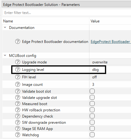
The bootloader logs the status and reports over the serial port during the boot and upgrade process. The logs are printed over an UART port and are determined based on the log levels that are set during the compile time.
This is a configurable feature that can be enabled/disabled during compile time.
Five levels of logging are supported.
MCUBOOT_LOG_LEVEL_OFF (0)
MCUBOOT_LOG_LEVEL_ERROR (1)
MCUBOOT_LOG_LEVEL_WARNING (2)
MCUBOOT_LOG_LEVEL_INFO (3)
MCUBOOT_LOG_LEVEL_DEBUG (4)
Logging level can be configured in the bootloader solution as shown below.
Figure 42.
Set EPB log level
Fault Injection Hardening (FIH)
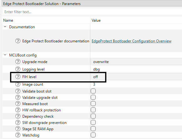
To mitigate hardware-based fault injection attacks (for example, power glitching, EM pulses) aimed at executing unauthorized code, MCUboot incorporates software countermeasures. These attacks exploit induced CPU behavior changes like skipped instructions, modified registers, corrupted memory reads, or altered instruction decoding to bypass security mechanisms.
While these software countermeasures enhance resistance to fault injection attacks, they do not provide absolute protection. Their activation is controlled by the MCUBOOT_FIH_PROFILE_* macros, offering four protection levels: none, moderate, medium, and maximum. These countermeasures are primarily integrated into the core MCUboot codebase (<ifx-mcuboot-pse84>/<version>/boot/bootutil/src), focusing on critical code paths susceptible to fault injection.
The fault injection mitigation library has support for different measures, which can either be enabled/disabled separately or by defining one of the MCUBOOT_FIH_PROFILEs.
Figure 43.
Set FIH level in the bootloader solution
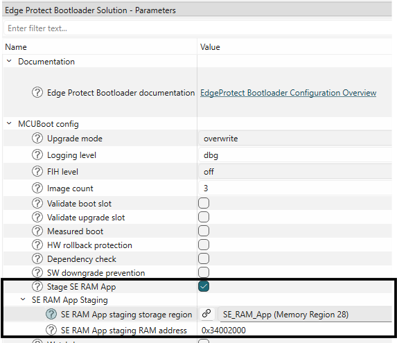
SE RT services update
In EPC 4 devices, the Secure Enclave runtime services (SE RT) library may be updated using the SE RAM App staging feature of EPB. This feature allows users to use the EPB to stage the SE RT Services update RAM application from a persistent storage region and indicate to the ROM Boot to execute it. The SE RAM App must be placed in a storage region (using OTA or other mechanism). During boot up, the EPB checks the storage region for the presence of the RAM application. It then copies the application from the storage region to the specified RAM address. EPB then notifies the ROM Boot about the staged SE RAM application. It then performs a soft reset to transfer control to the ROM Boot. ROM Boot takes control and executes the RAM application. After completion, control is transferred to EPB. EPB takes control and checks the RAM App execution status. It then erases the RAM App from the storage region to prevent it from being staged again.
This feature can be enabled in the Bootloader solution as shown below.
Select
SE RAM App staging storage region
and choose a memory region where the RAM application will be stored
Select
SE RAM App staging RAM address
and specify the target RAM address where the application will be copied for execution
Figure 44.
Enable SE RAM App staging
Note:
Refer to
PSOC™ Edge provisioning specification
for more details on SE RAM application staging and execution.
Bootloader in different memories
Bootloader can be executed from the different memories supported on the device, such as RRAM, external flash and internal RAM memory. The following sections describe how to configure the EPB to execute from different memories.
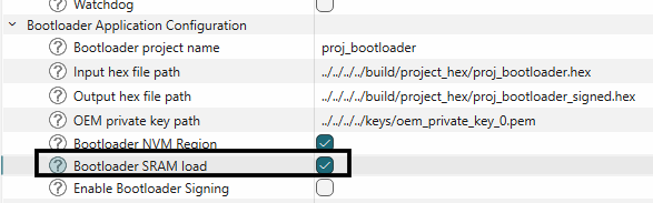
Bootloader in SRAM
The Edge Protect Bootloader image which is programmed to NVM memory can be loaded and executed from the SRAM at device boot up. The SRAM loading in this case is done by the Extended Boot. To enable the SRAM loading of the bootloader image, follow the steps below.
The bootloader image must be compiled to execute from the SRAM memory. This requires changes to the existing linker files. Pre-configured linkers are provided with the Edge Protect Bootloader code example. Copy the linker from the
<EPB-application-dir>/templates/<TARGET>/COMPONENT_CM33/<TOOLCHAIN>/bootloader_sram.ld
to the bsp directory of the code example
<application-dir>/bsps/<TARGET>/COMPONENT_CM33/<TOOLCHAIN>/bootloader_sram.ld
Enable the SRAM loading of the EPB in the bootloader solution as shown
Figure 45.
Enable bootloader in SRAM
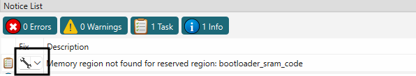
Add region in SRAM memory for bootloader image by clicking on fix as shown below.
Figure 46.
Add bootloader_sram_code region
Edit the offset of bootloader to start from 0x00008000 offset. Adjust other memory regions in SRAM as needed
Figure 47.
Allocate bootloader_sram_code in the SRAM
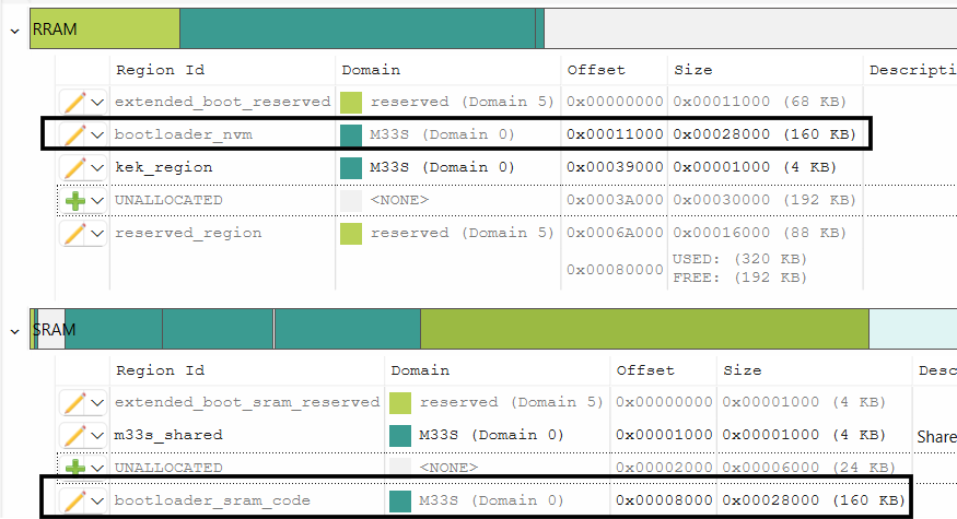
Note:
bootloader_sram_code
region should be placed with 0x00008000 offset from the start in SRAM. Size of
bootloader_sram_code
has to be at least the size generated bin file. To fit this region, re-size other regions in the SRAM.
Bootloader in external flash memory
The Edge Protect Bootloader is placed in RRAM for the default use case demonstrations. For the EPB to be placed in the External flash memory, follow the steps below.
Move the "bootloader_nvm" region in the 'Memory' tab of the Device configurator from RRAM to Serial Memory Interface block as shown. Specify the offset
0x00100000
Figure 48.
Move region to external flash
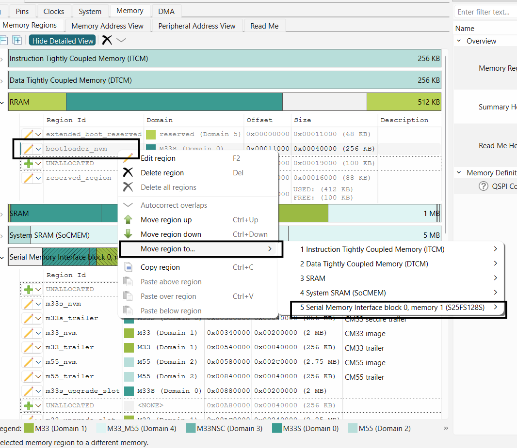
Note:
"bootloader_nvm" region must start at 0x00100000 offset to be successfully launched by the Extended Boot. If you want to place your first application in offsets other than 0x00100000, then you must provision the device with updated OEM policy file. This topic is out of scope of this document
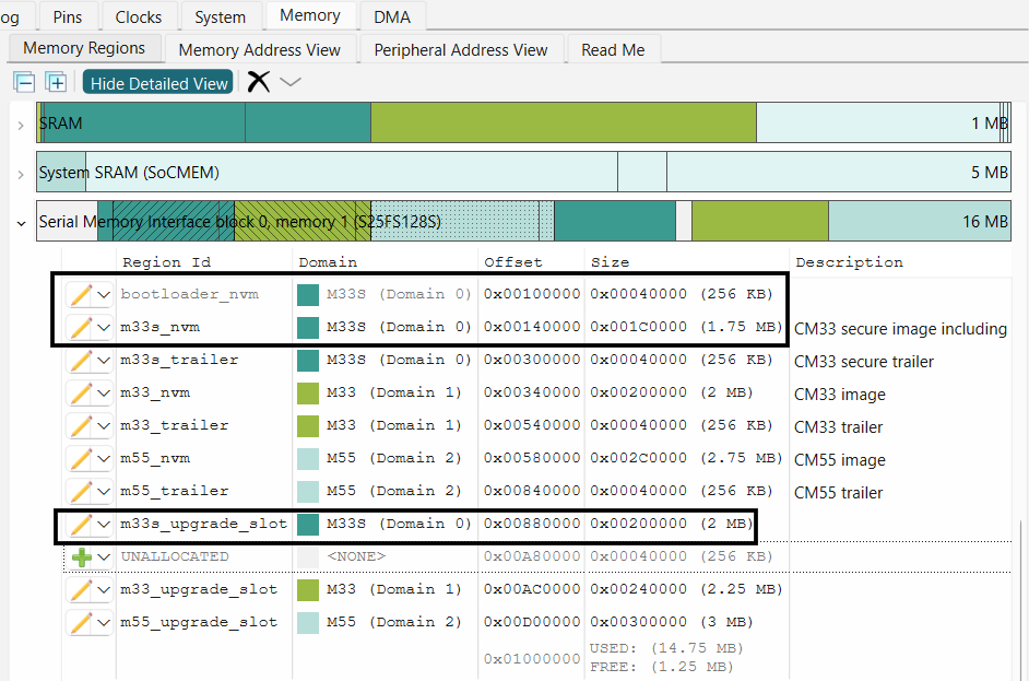
Resize other application in the external memory to accommodate the bootloader image
Figure 49.
Bootloader in external flash
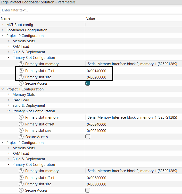
Update the primary slots information for applications in the bootloader solution
Figure 50.
Update the bootloader solution parameters
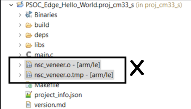
If you had previously compiled your application, delete the veneer files in the "proj_cm33_s" directory since you have now relocated your proj_cm33_s application. This is not required this application was not compiled before.
Figure 51.
Delete veneer file
Note:
When using the extended boot to launch an image from an external flash, the
BOOT
SW
on your EVK must be in the ON/HIGH position
Bootloader in RRAM
The bootloader in RRAM is the default configuration of the EPB and instructions to configure it are covered in
Adding EPB to ModusToolbox™ code examples
OctalSPI flash memory support
Edge Protect Bootloader supports booting applications from the external OctalSPI flash. To enable Octal SPI support , follow the instructions below.
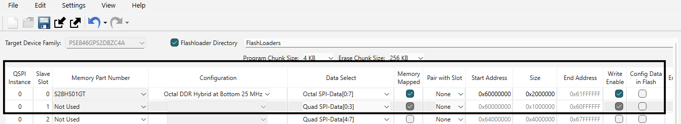
In the QSPI configurator, select the OSPI Memory part number and select the configuration as needed. Disable the Quad SPI memory. An example configuration for OSPI supported by the PSOC™ Edge EVK is as shown below
Figure 52.
Enable the OSPI flash in QSPI configurator
Allocate the memory regions for the applications in Memory Tab of the device configurator
Figure 53.
Allocate memory for Octal flash memory
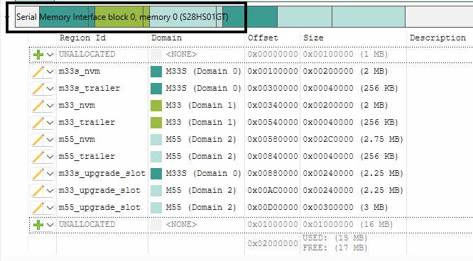
Note:
The Region Ids are used in the default linker files. If Region Id is changed, linker files for the respective applications must also be updated
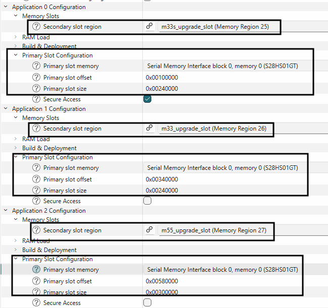
Update primary and secondary slot information in the bootloader solution.
Figure 54.
Update slot information in bootloader solution
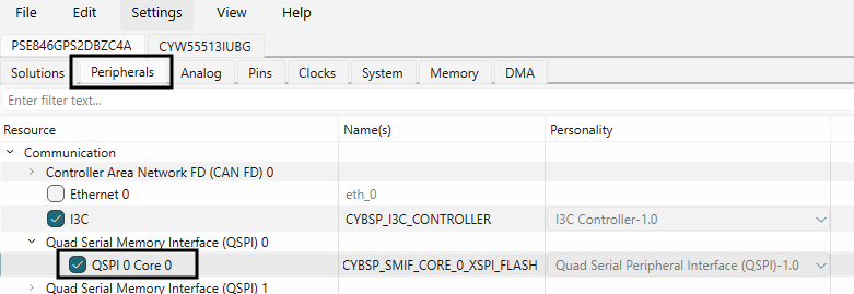
In the Device configurator's Peripherals Tab, choose the QSPI 0 Core 0.
Figure 55.
Click on QSPI 0 Core 0
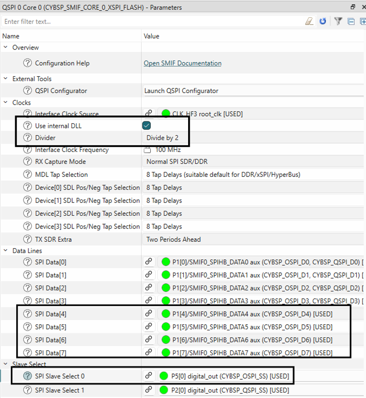
Make the following changes in the Parameters view of QSPI Core 0
Figure 56.
Configure for OSPI flash
Glossary
AES
Advanced Encryption Standard
CM33
Arm® Cortex® M-33
CM55
Arm® Cortex® M-55
CPU
Central Processing Unit
ECC
Elliptic curve cryptography
EPB
Edge Protect Bootloader
EPC
Edge Protect category
FIH
Fault Injection Hardening
HKDF
HMAC based key derivation function
HMAC
Hash based Message authentication code
NSPE
Non secure processing environment
OEM
Original Equipment Manufacturer
PEM
Privacy Enhanced Mail
PSA
Platform Security Architecture
RRAM
Resistive Random Access Memory
SE
Secure Enclave
SE RAM App
Secure Enclave RAM application
SE RT service
Secure Enclave Run-time services
SMIF
Serial Memory Interface
SPE
Secure Processing Environment
SPI
Serial Peripheral Interface
SRAM
Static Random Access Memory
TLV
Tag Length value
XIP
Execute In Place
Revision history
Document revision | Date | Description of changes |
|---|---|---|
** | 2025-10-14 | Initial release. |