AN238090 Connecting to cloud services using ModusToolbox™
About this document
Scope and purpose
This application note delves into the IoT cloud connectivity solutions on Infineon Microcontrollers (MCUs). Application note provides in-depth information on how to seamlessly connect to cloud services, such as Microsoft's Azure and Amazon's AWS for IoT applications leveraging Infineon MCUs. It covers the fundamental concepts of connectivity and cloud provider services and guides through the creation of connectivity applications, including configuring IoT cloud service assets, generating authentication credentials, programming application code, and running projects, ultimately empowering developers to design and implement efficient IoT solutions using Infineon MCUs.
Intended audience
This application note is intended for users who wants to work on cloud connectivity applications on Infineon MCUs such as PSOC™ Edge E8 using the ModusToolbox™ software.
Introduction
This application note will provide information how IoT applications on Infineon MCUs using ModusToolbox™ software tools can establish connection with cloud services like Amazon Web Services (AWS) and Microsoft Azure.
Third-party IoT Embedded SDKs like Azure SDK for Embedded C and AWS IoT Device SDK for Embedded C uses to simplify connecting these devices to cloud platforms (Azure or AWS) by providing secure communication, data management, and device management functionalities. These SDKs save development time and ensure security, making them valuable tools for building efficient IoT applications.
See
AN236697 - Getting started with PSOC™ Edge MCU and AIROC™ connectivity devices
to know more about the Infineon’s connectivity devices. See
AN228571 – Getting started with PSOC™ 6 MCU on ModusToolbox™ software
for PSOC™ 6 family series and
Getting started with PSOC™ Edge E8 on ModusToolbox™ software
to know how to use Infineon MCUs. These application notes provide an overview of the MCU and the information needed to get started. Additionally, see the datasheet of the corresponding MCU for more information. PSOC™ Edge MCU is used to demonstrate a range of applications within this document.
Amazon Web Services (AWS)
AWS is a secure cloud services platform offering compute power, database storage, content delivery, and other functionalities. AWS is built from a vast array of both virtual and actual servers and networks as well as a large number of web server software and administrative tools.
AWS IoT:
A cloud platform that provides cloud services for IoT devices. The AWS IoT Cloud service supports MQTT Message Brokers, HTTP access, and a bunch of server-side functionality that includes:
A virtual MQTT Message Broker and HTTP server
Thing Registry:
A web interface to manage the access to your AWS Things
Security and identity:
A web interface to manage the certificates and rules about things. You can create encryption keys and manage access privileges
Shadow:
An online cache of the most recent state of your thing
Rules Engine:
An application that runs in the cloud can subscribe to topics and take programmatic actions based on messages – for example, configure it to subscribe to an "Alert" topic, and if a thing publishes a warning message to the "Alert" topic, it uses Amazon SNS to send an SMS text message to your cellphone
IoT applications:
An SDK to build webpages and cellphone applications
The
AWS IoT Device SDK for Embedded C
is a collection of C source files provided by AWS that allow developers to securely connect embedded devices to AWS IoT Core. This lightweight SDK is specifically designed for embedded systems with limited processing power and memory resources.
Microsoft Azure Web Services
Microsoft Azure is a comprehensive suite of cloud computing services from Microsoft. It provides a wide range of on-demand services for building, deploying, and managing applications across a global network of data centers. It is a web-based interface that acts as the central command center for managing all resources in Microsoft's Azure cloud computing platform. It provides a user-friendly graphical interface, eliminating the need for complex code commands.
The
Azure SDK for Embedded C
is a development tool designed to connect resource-constrained microcontroller devices to Microsoft Azure services. The
Azure Core Library for Embedded C
acts like a shared toolkit for various Azure client libraries written in C code. This library provides common building blocks and functionalities, ensuring a consistent experience when working with different Azure services.
Overview
This document provides comprehensive guidance on initiating interactions with AWS and Azure platforms. Detailed instructions on establishing authentication credentials for communication with AWS and Azure web services are provided, along with illustrative code examples which are described in sections
Getting started with AWS communication
and
Getting started with Azure communication
respectively.
Hardware and software requirements
section provides the required hardware and software prerequisites.
Hardware and software requirements
This section describes the required hardware and software prerequisites for the code example demonstration exhibited in
Getting started with AWS communication
and
Getting started with Azure communication
sections.
Hardware requirements
This document applies to PSOC™ Edge E84 Evaluation Kit with the Edge Protect Category 2 (EPC 2) part (KIT_PSE84_EVAL_EPC2), Edge Protect Category 4 (EPC 4) part (KIT_PSE84_EVAL_EPC4) and PSOC™ 6 family series (PSOC™ 61, PSOC™ 62, PSOC™ 63, PSOC™ 64). Adapt the prerequisites and other sections that are specific to PSOC™ Edge E84 and PSOC™ 6 according to the kit that you are using. See the
References
section for documents related to the kit.
For the design example shown in this application note, the minimum required revision for the PSOC™ Edge E84 Evaluation kit (KIT_PSE84_EVAL_EPC2) is Rev *G.
Software requirements
This section provides a brief overview of the software dependencies utilized.
ModusToolbox™ for cloud services
The ModusToolbox™ software is a modern, extensible development environment for Infineon MCUs for applications ranging from wireless and cloud-connected systems, edge AI/ML, embedded sense and control, to wired USB connectivity using PSOC™ Industrial/IoT MCUs, AIROC™ Wi-Fi and Bluetooth® connectivity devices, XMC™ Industrial MCUs, and EZ-USB™/EZ-PD™ wired connectivity controllers. It provides a flexible set of tools and a diverse, high-quality collection of application-focused software. These include configuration tools, low-level drivers, libraries, and operating system support, most of which are compatible with Linux, macOS, and Windows-hosted environments.
The complete set of run-time software connectivity libraries fit together with the core PSOC™ libraries as shown in
Figure 1
.
Figure 1.
ModusToolbox™ for connectivity
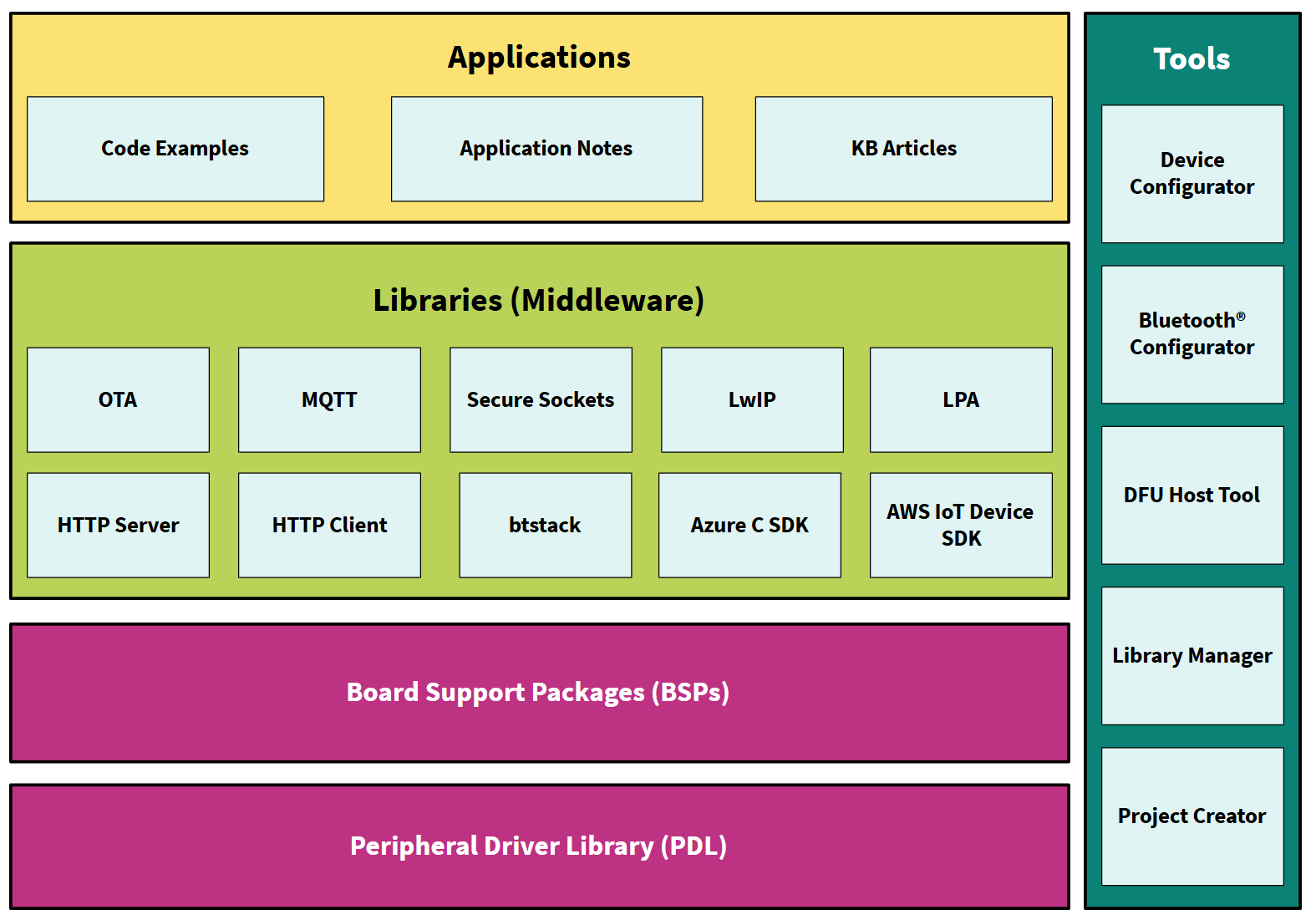
The run-time software is distributed as a collection of libraries that work together to help you easily get your IoT device up and running on the cloud. Some of the libraries are from Infineon, while others are industry standard open-source libraries and can be pulled into a ModusToolbox™ application easily by using the Library Manager.
Python
Download the official Python version 3.8-3.12 from the
Python
website. After installation, add the Python directory to your system path environment variables, which allows you to easily run the Python commands from anywhere in your terminal.
AWS IoT Device SDK Port Library
AWS IoT Device SDK Port Library
is a port layer implementation for Infineon
MQTT client library
and
HTTP client library
. It can work with
AWS IoT Device SDK Embedded C
library on Infineon connectivity-enabled MCU platforms. See
aws-iot-device-sdk-port
for more information on the library.
This port library is a dependency for the
PSOC™ Edge MCU: Wi-Fi MQTT client
code example and is automatically pulled into the project at the time of application creation.
Azure C SDK Port Library
implements the port layer for the
Azure SDK for Embedded C
to work on PSOC™ Edge E8 MCU and PSOC™ 6 MCU connectivity-enabled platforms. This library automatically pulls the
Azure SDK for Embedded C
library and the port layer functions implemented by this library are used by the
Azure SDK for Embedded C
library. If your application needs an Azure SDK for Embedded C library with MQTT client functionality, it needs to explicitly import the MQTT library.
See the
azure-c-sdk-port
for more information on the library.
A few dependencies as follows:
Microsoft Azure SDK for Embedded C library
Wi-Fi middleware core
HTTP client
Azure IoT SDK port
FreeRTOS PKCS11 PSA
This port library is a dependency for the
PSOC™ Edge MCU: Connecting to Azure IoT using Azure SDK for C
code example and is automatically pulled into the project at the time of application creation.
MQTT Client library
It contains an MQTT Client library that can work with the family of Infineon connectivity devices. This library uses the AWS IoT Device SDK MQTT Client library and implements the glue layer that is required for the library to work with Infineon connectivity platforms
ModusToolbox™ AWS MQTT Client and Azure IoT code examples download this library automatically, so you do not need to. ModusToolbox™ AWS MQTT Client and Azure IoT code examples download this library automatically, so you do not need to
Getting started with AWS communication
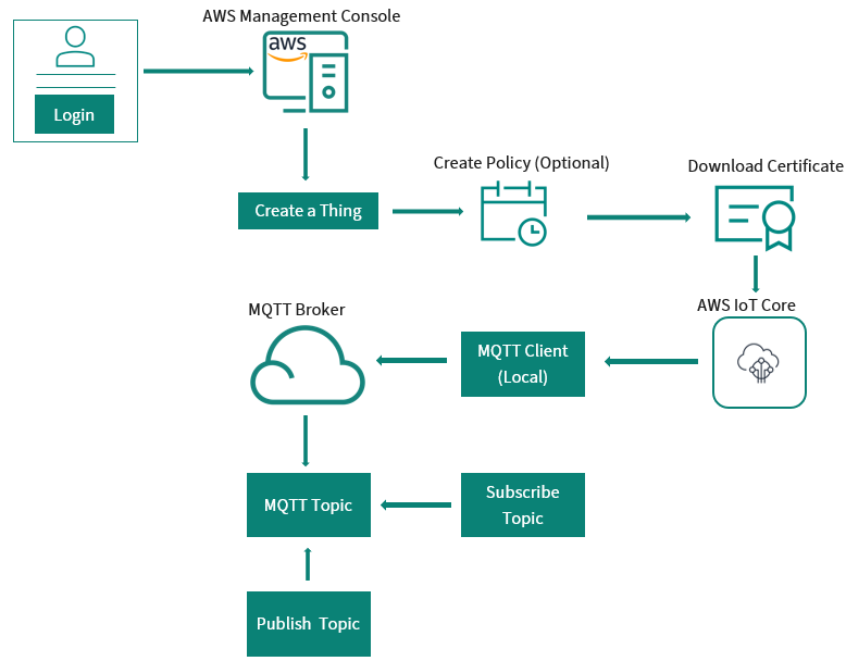
AWS credential setup
Infineon's connectivity device for IoT solutions will connect and communicate using the AWS IoT Device SDK and MQTT libraries. This section will discuss some of the concepts that are important to know when connecting your IoT device to AWS.
Figure 2.
AWS authentication process
AWS IoT resources
There are three types of resources in AWS: Things, Certificates, and Policies. The following sections will guide you into the step-by-step process to create each of them.
AWS Thing
A thing is a representation of a device or logical entity. It can be a physical device or sensor (for example, a light bulb or a switch on a wall). It can also be a logical entity like an instance of an application or a physical entity that does not connect to AWS IoT but can be related to other devices that do (for example, a car that has engine sensors or a control panel).
Certificate
AWS IoT provides mutual authentication and encryption at all points of connection so that data is never exchanged between things and AWS IoT without a proven identity. AWS IoT supports X.509 certificate-based authentication. Connections to AWS use certificate-based authentication. You must attach policies to a certificate to allow or deny access to AWS IoT resources. Your device uses a root CA (certification authority) to ensure it is communicating with the actual Amazon Web Services site. You can only connect your thing to the AWS IoT Cloud via TLS.
Policy
After creating a certificate for your internet-connected thing, you must create and attach an AWS IoT policy that will determine what AWS IoT operations the thing can perform. AWS IoT policies are JSON documents and they follow the same conventions as AWS Identity and Access Management policies. You can specify permissions for specific resources such as topics and shadows.
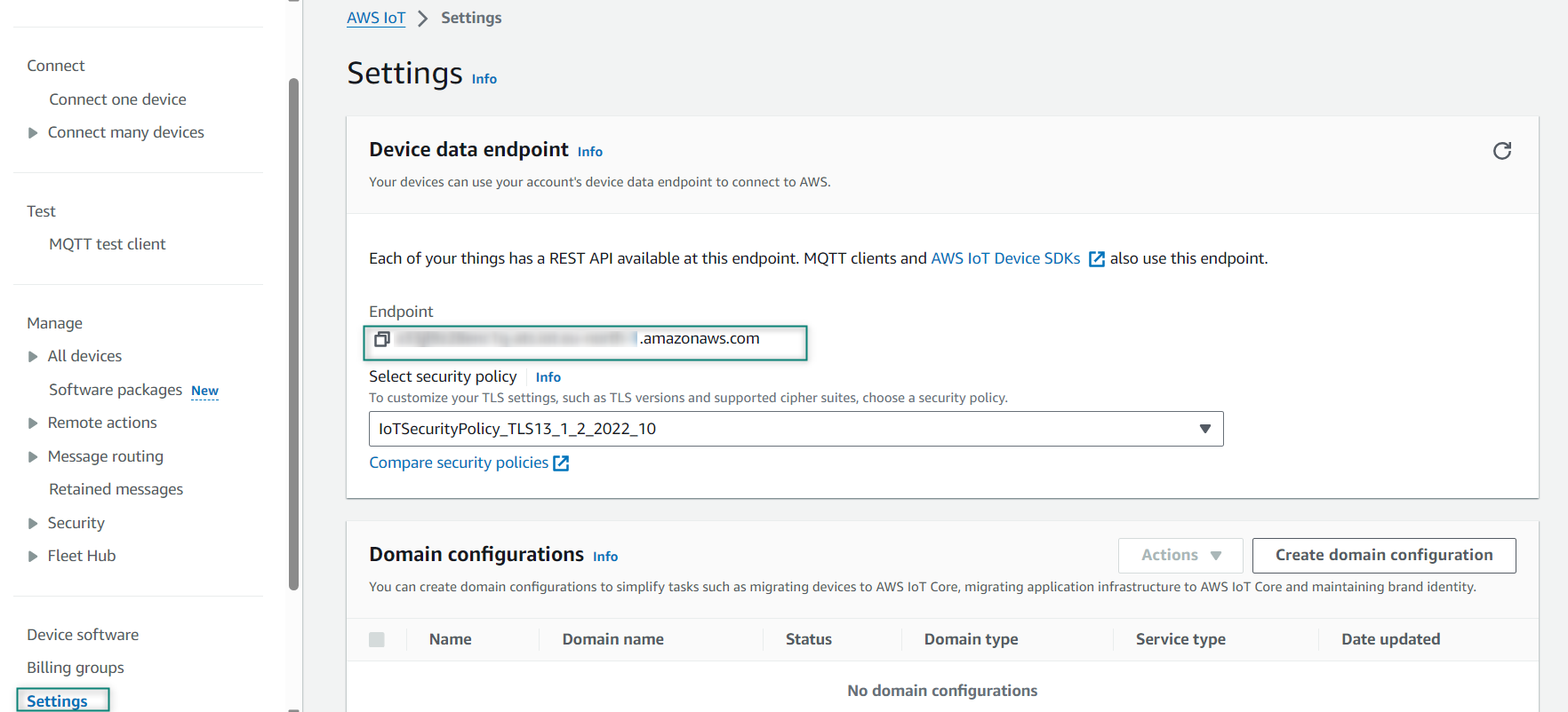
Creating an AWS IoT account
To create a new AWS account, you need to provide billing information. The basic account is free for the first year and is chargeable after that. Please read the terms and conditions on the AWS website for the details of the same. When you create an AWS IoT account, Amazon will create a new virtual machine for you in the cloud and will turn on an MQTT Message Broker and an HTTP server on that machine. To connect your device to the machine, you need to know the DNS name of the virtual machine. To find the virtual machine's DNS name, click on
Settings
at the lower left corner of the AWS IoT console window as shown in
Figure 3
. The name is listed as the Endpoint.
Figure 3.
DNS name
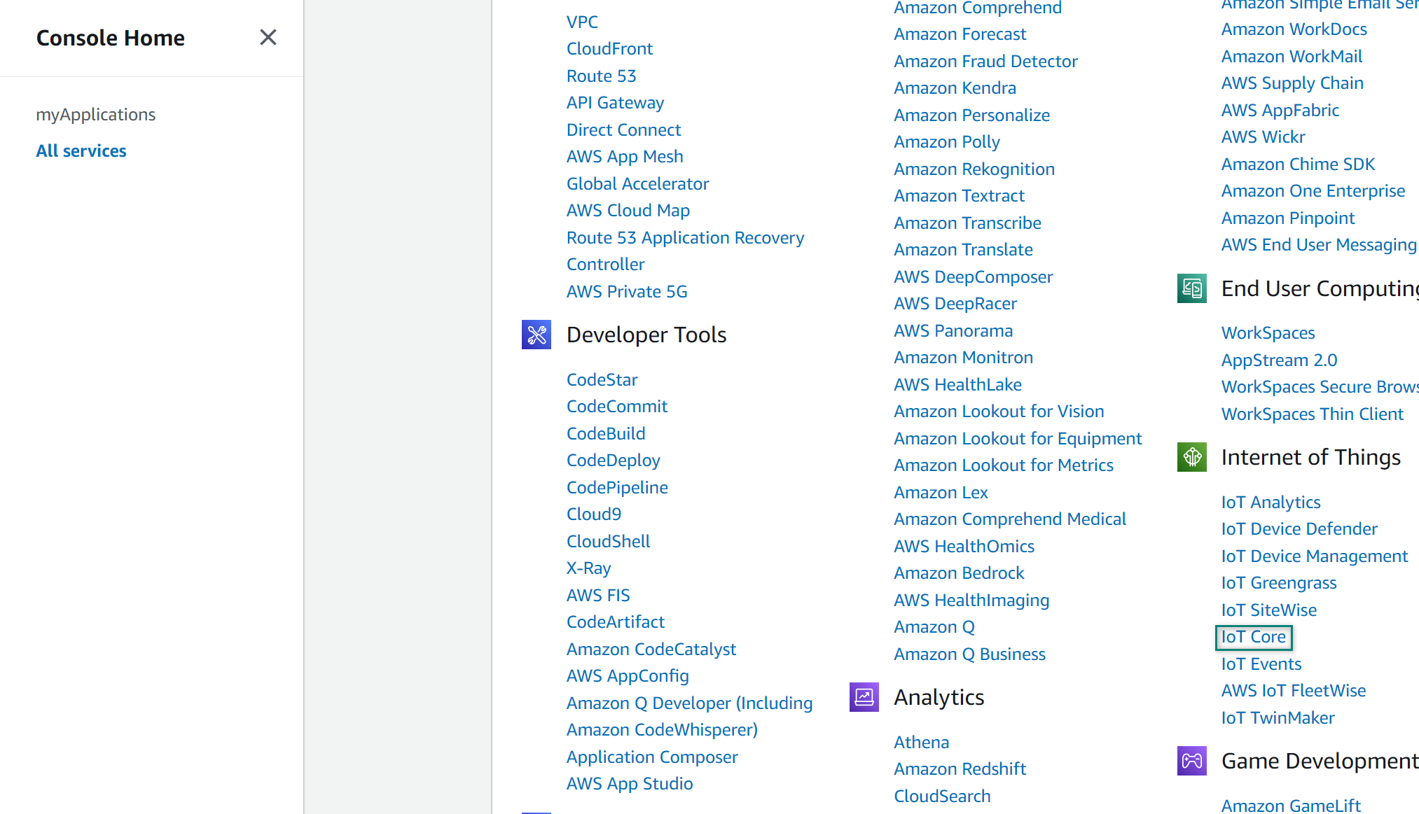
Create Thing
Create a new AWS Thing, provision a new thing in the AWS IoT Cloud, and establish its policy and credentials
After log in from the Services menu, select
IoT Core
Figure 4.
AWS Services - IoT Core
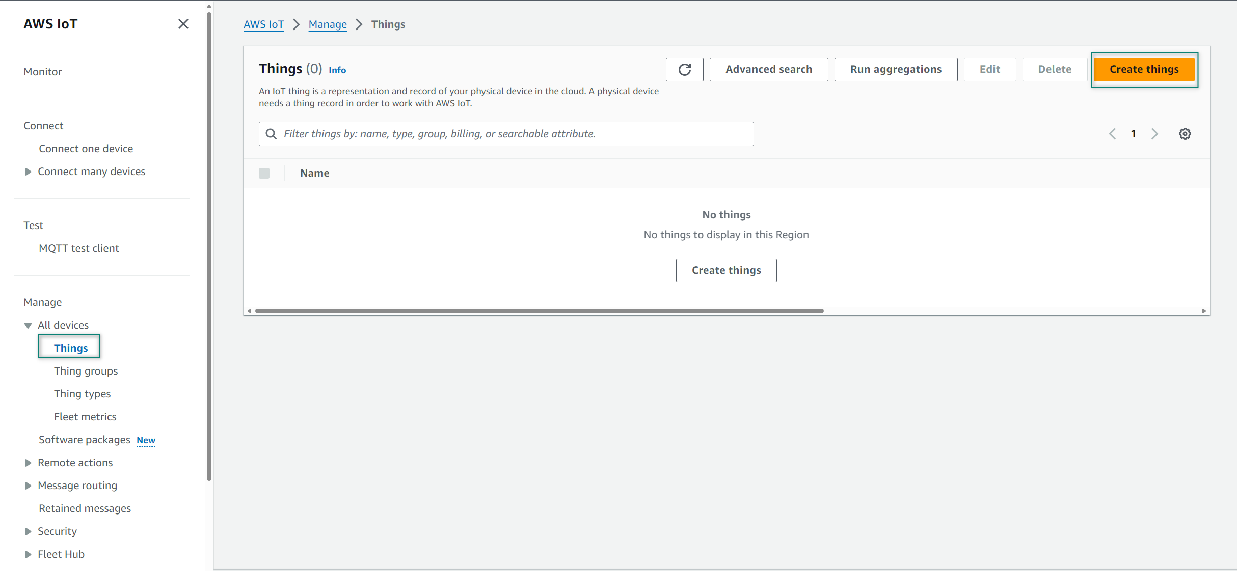
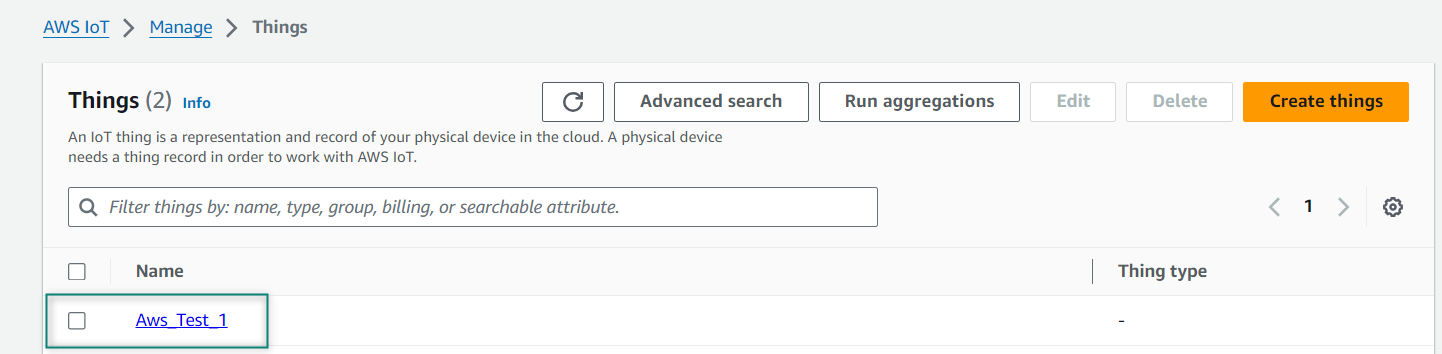
Select
Things
from the Manage section and click
Create things
Figure 5.
Create Thing
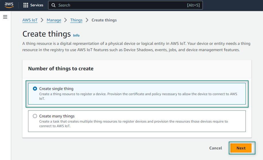
Select
Create single thing
from Create things and click
Next
Figure 6.
Create single thing
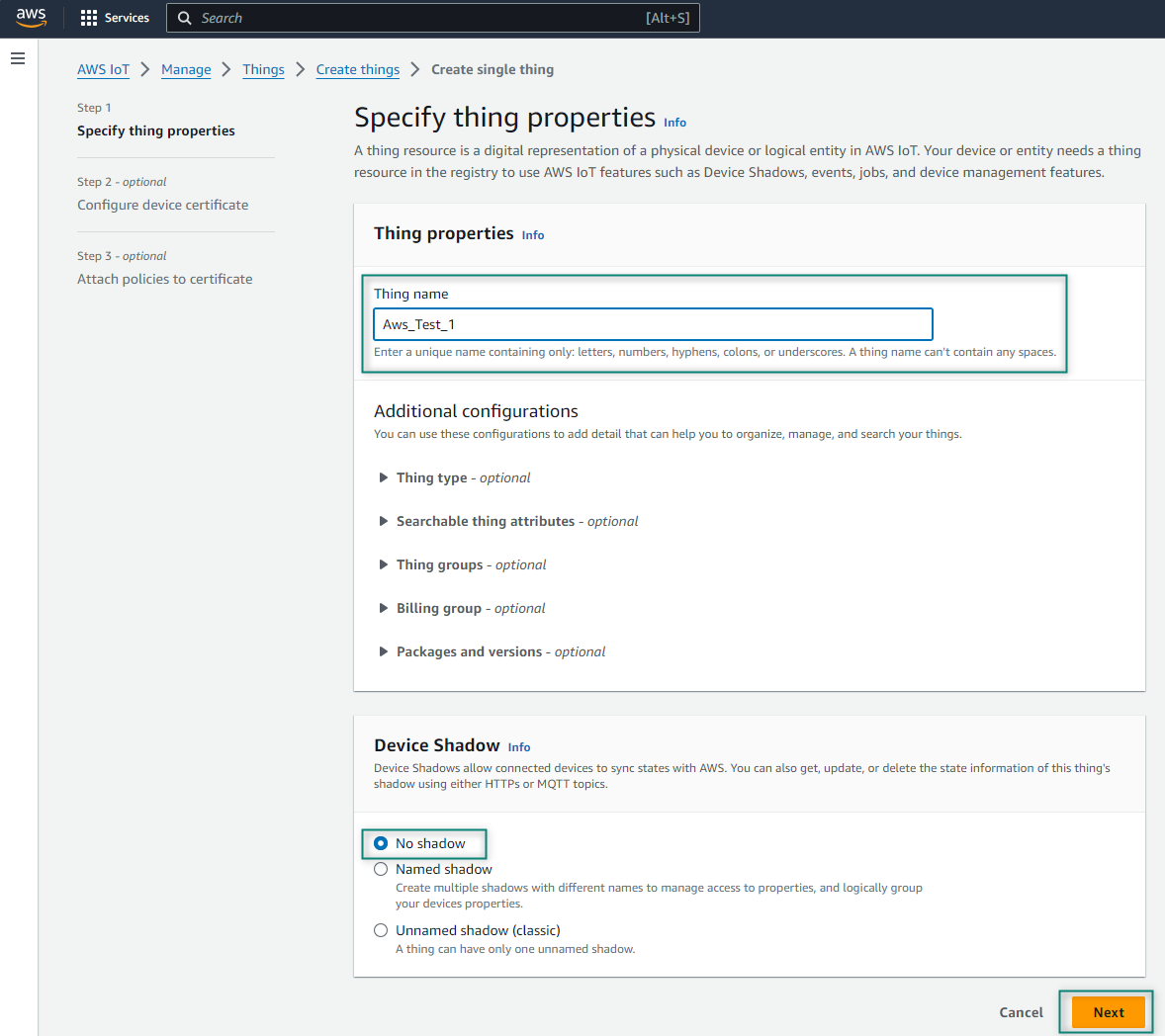
Name your thing, select
No shadow
in Device Shadow, and click
Next
. Here,
Aws_Test_1
name is used for the thing that will be used for development
Figure 7.
Thing name
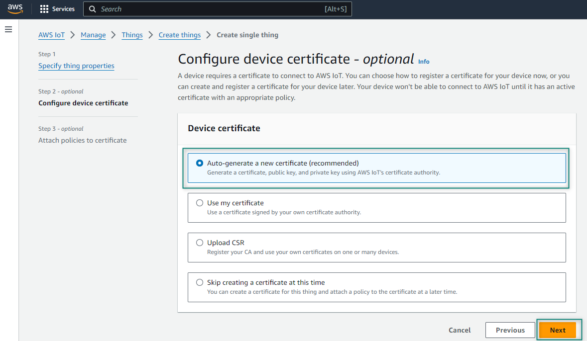
Before you access the broker from your kit, you need to create the encryption keys that enables you to identify it as an allowed device. To do this, find your thing in the list of things and select it. If you do not see it in the list, you can search for it using the search box at the upper right corner of the window. One you get to your thing's page, click Security, select
Auto-generate a new certificate (recommended)
from Device certificate and then click
Next
Figure 8.
Configure device certificate
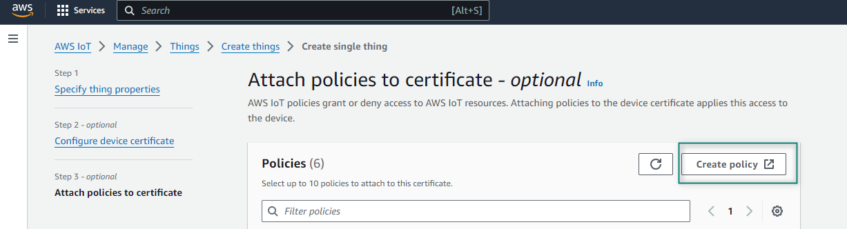
Click
Create policy
from Policies
Figure 9.
Create policy
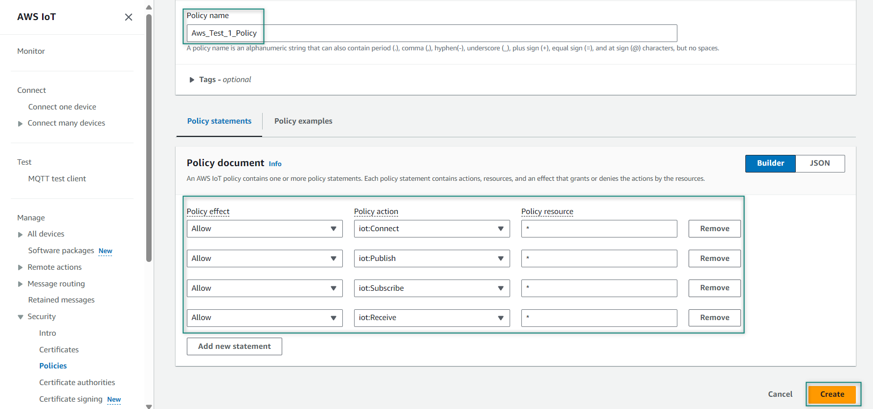
Enter the Policy name that you want to create. Here, the
Aws_Test_1_Policy
name is used. While setting up your device, ensure that the policy associated with this device permits all MQTT operations (iot:Connect, iot:Publish, iot:Subscribe, and iot:Receive) for the resource used by this device. For testing purposes, use the following Policy document properties that allows you to all the MQTT Policy Actions on all Amazon Resource Names (ARNs) as shown in
Figure 10
Figure 10.
Policy details
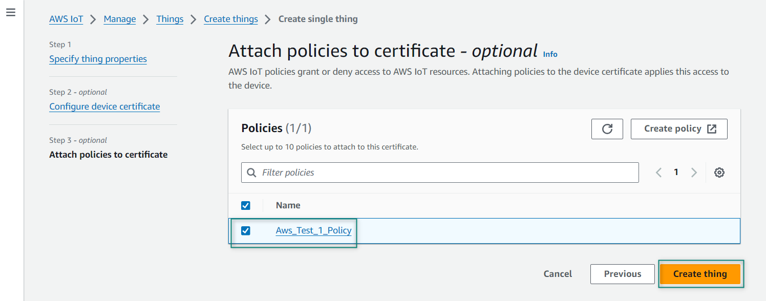
Select the created policy and click
Create thing
Figure 11.
Attach policy
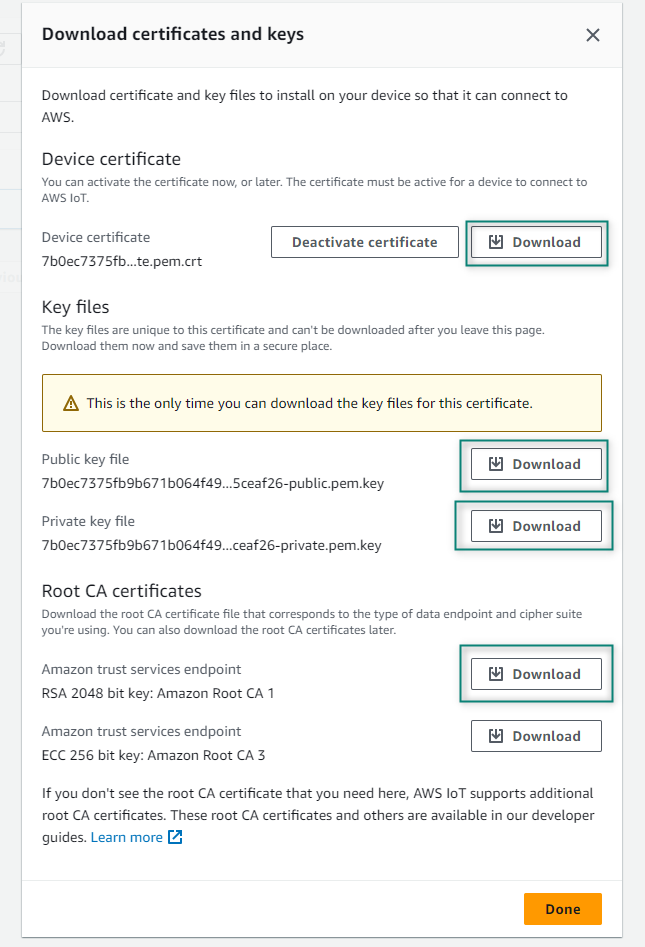
After attaching the policy, it shows all the required certificates that can be downloaded as shown in
Figure 12
to download. Note that these certificates cannot be downloaded in the later steps and click
Done
Figure 12.
Certificate and keys
After that the Thing is created as shown in
Figure 13
Figure 13. AWS Thing
Using the AWS MQTT test client
To test the MQTT client, the
AWS
website has an MQTT test client to test publishing and subscribing to topics. Consider the MQTT test client as a terminal window into your message broker, or as a generic IoT thing that can publish and subscribe topics and use this client to test the tasks. Alternately, you can run two tabs in your browser – one to subscribe and one to publish.
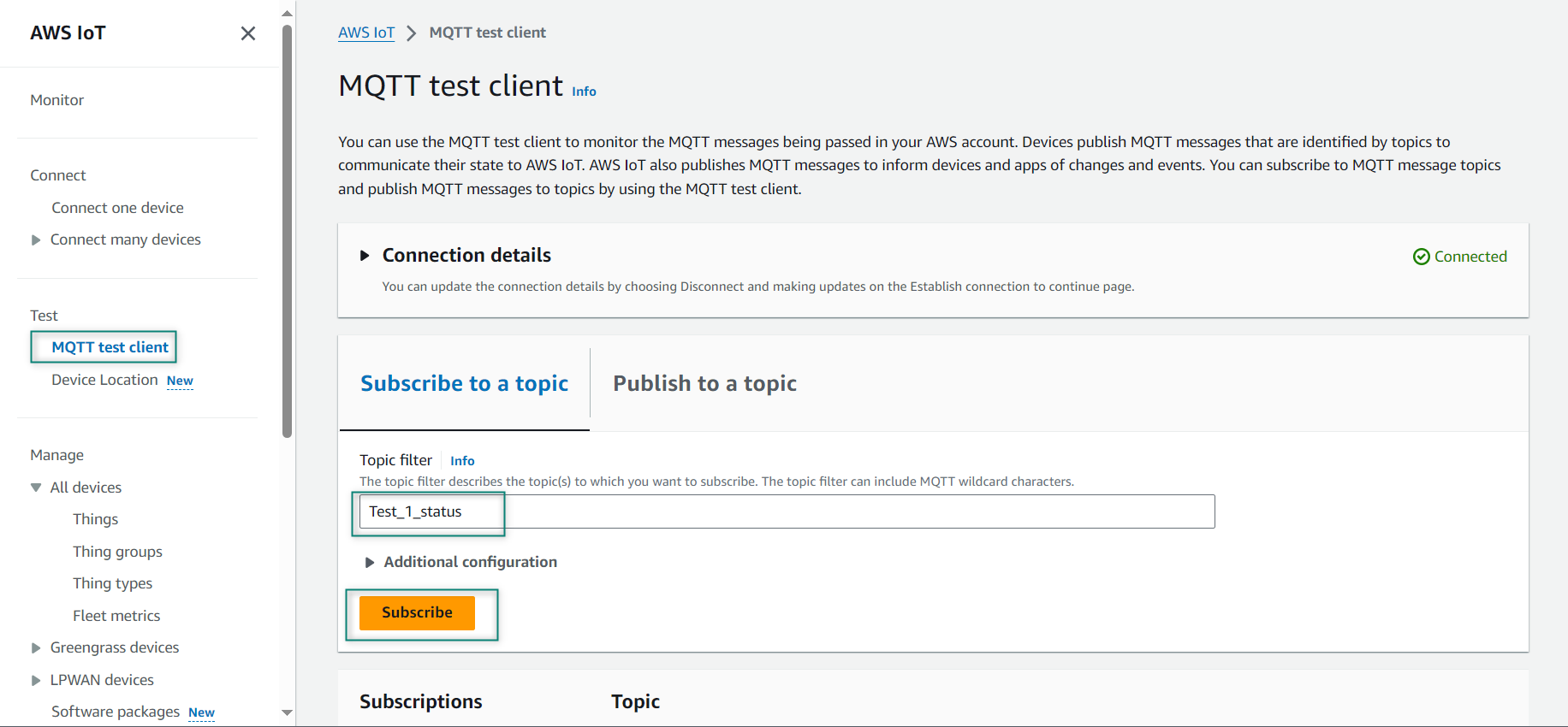
Select
on the left side of the AWS IoT
Enter a topic that you want to subscribe in the Topic filter such as
Test_1_status
Select Display payloads as strings and click
Subscribe
to topic
Figure 14.
Subscribe to a topic
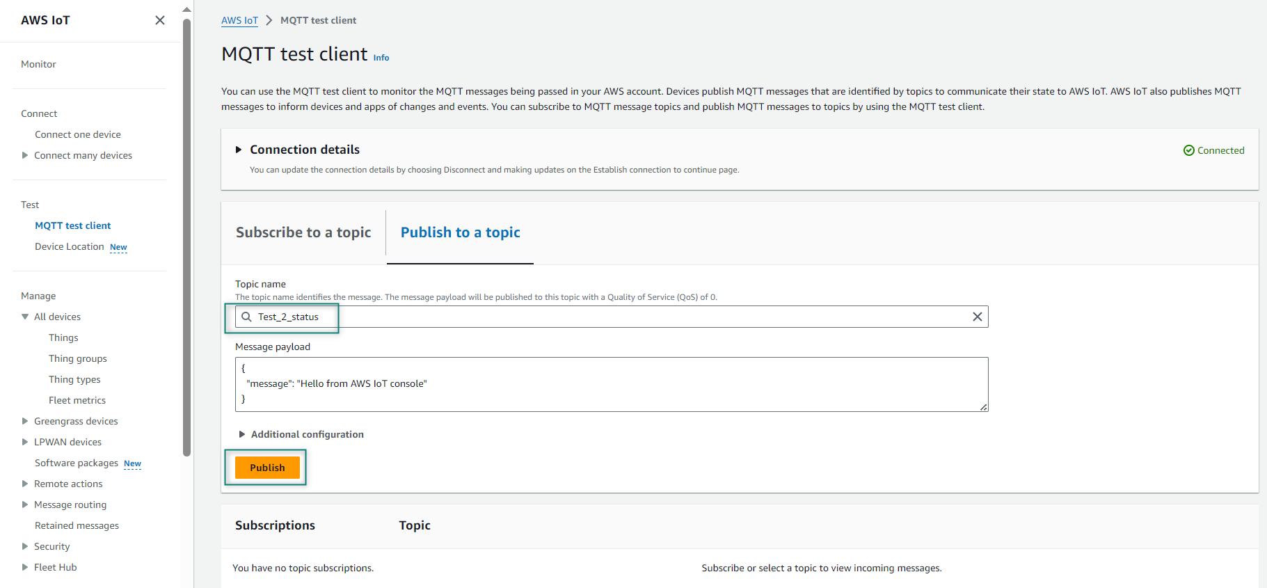
Enter a topic that you want to publish such as
Test_2_status
in the Topic name, click
Publish
. The payload will be sent to the subscriber
Figure 15.
Publish Topic
Connecting to MQTT client using AWS
This section describes how to build an AWS-based application for PSOC™ Edge E84 device using Eclipse IDE for ModusToolbox™. This code example (
PSOC™ Edge MCU: Wi-Fi MQTT client
) that is going to be demonstrated implements an MQTT client using the
MQTT library
on PSOC™ Edge MCU. The library uses the AWS IoT Device SDK Port library and implements the glue layer that is required for the library to work with Infineon connectivity platforms.
Prerequisites
Before you start, ensure that you have the appropriate development kit for the PSOC™ Edge E84 MCU product line, and have installed the required software. For more details, see
Hardware and software requirements
.
Application development
The following sections provide guidelines on how to develop an application:
Create a new application
View and modify the design
Develop your application
Build the application
Program the device
Test your design
Note:
This design is developed for the PSOC™ Edge E84 Evaluation Kit (KIT_PSE84_EVAL_EPC2).
About the design
This example implements three RTOS tasks: MQTT client, publisher, and subscriber. The main function initializes the BSP and the retarget-io library, and creates the MQTT client task.
The MQTT client task initializes the Wi-Fi Connection Manager (WCM) and connects it to a Wi-Fi Access Point (AP) using the Wi-Fi network credentials that are configured in the
wifi_config.h
file. After a successful Wi-Fi connection, the task initializes the MQTT library and establishes a connection with the MQTT broker/server.
The MQTT connection is configured to be secure by default; the secure connection requires a client certificate. Client certificate contains information about your device and is signed by a trusted Certificate Authority (CA), a Private Key (private key that is to be kept secured), and the Root CA certificate (during connection, verifies the authenticity of the server certificate presented by AWS IoT) of the MQTT broker that are configured in the
mqtt_client_config.h
file.
After a successful MQTT connection, the subscriber and publisher tasks are created. The MQTT client task then waits for commands from the other two tasks and callbacks to handle events like unexpected disconnections.
The subscriber task initializes the user LED GPIO and subscribes to messages on the topic specified by the
MQTT_SUB_TOPIC
macro that can be configured in the
mqtt_client_config.h
file. When the subscriber task receives a message from the broker, it turns the user LED ON or OFF depending on whether the received message is "TURN ON" or "TURN OFF" (configured using the
MQTT_DEVICE_ON_MESSAGE
and
MQTT_DEVICE_OFF_MESSAGE
macros).
The publisher task sets up the user button GPIO and configures an interrupt for the button. The ISR notifies the publisher task upon a button press. The publisher task then publishes messages (TURN ON/OFF) on the topic specified by the
MQTT_PUB_TOPIC
macro. When the publish operation fails, a message is sent over a queue to the MQTT client task.
An MQTT event callback function
mqtt_event_callback()
invoked by the MQTT library for events like MQTT disconnection and incoming MQTT subscription messages from the MQTT broker. In the case of an MQTT disconnection, the MQTT client task is informed about the disconnection using a message queue. When an MQTT subscription message is received, the subscriber callback function implemented in
subscriber_task.c
file is invoked to handle the incoming MQTT message.
The MQTT client task handles unexpected disconnections in the MQTT or Wi-Fi connections by initiating reconnection to restore the Wi-Fi/MQTT connections. Upon failure, the publisher and subscriber tasks are deleted, cleanup operations of various libraries are performed, and then the MQTT client task is terminated.
Create a new application
This section provides a step-by-step guideline for creating a new application. It uses the Empty App starter application and manually adds the functionality from the Wi-Fi MQTT Client application. ModusToolbox™ is used in the instructions, but you can use any IDE or the command-line tool if you prefer.
If you are familiar developing projects with ModusToolbox™, you can use
PSOC™ Edge MCU: Wi-Fi MQTT client
starter application for PSOC™ Edge and
MQTT client
code example for PSOC™ 6 application. It is a complete design with all the firmware written for the supported kits. You can walk through the instructions and observe how the steps are implemented in the code example.
Launch Eclipse IDE for ModusToolbox™ to get started. It requires the Internet connection to download the assets from GitHub repositories.
The following sections provide the steps to start with a new empty application.
Select a new workspace
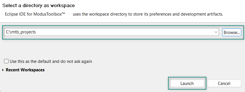
At launch, Eclipse IDE for ModusToolbox™ shows a dialog box to choose a directory as the workspace directory. The workspace directory is used to store workspace preferences and development artifacts such as device configuration and application source code. You can choose an existing empty directory by clicking the
Browse
button. Alternatively, you can type in a directory name to be used as the workspace directory along with the complete path, and ModusToolbox™ will create the directory for you.
Figure 16.
Select a directory as workspace
Create a new ModusToolbox™ application
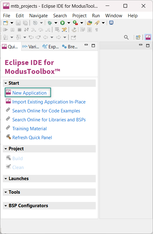
Click
New Application
in the Quick Panel, see
Figure 17
. Alternatively, go to
and click ModusToolbox™ Application.
Figure 17.
Create a new ModusToolbox™ application
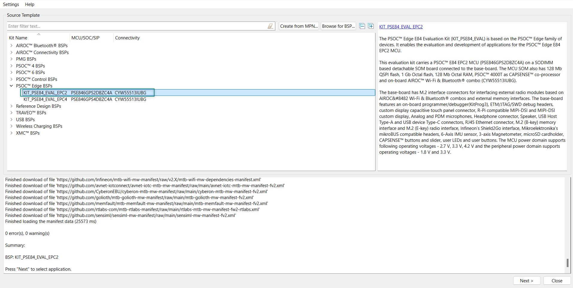
Select PSOC™ Edge E84 MCU-based target hardware
ModusToolbox™ lists the Infineon kits to start your application development. In this case, develop an application on the PSOC™ Edge E84 Evaluation Board that uses the PSOC™ Edge line device. Select KIT_PSE84_EVAL_EPC2 and click
Next
as shown in
Figure 18
.
Figure 18.
Choose target hardware
Select a PSOC™ Edge Empty application and create the application (applicable only for “Working from Scratch” flow)
Use an existing empty application as the starting point for the Working from Scratch development flow.
This is a minimal empty application template for PSOC™ Edge MCU devices. This example uses FreeRTOS to blink two LEDs with different frequencies respectively from the Arm® Cortex®-M33 CPU and the Arm® Cortex®-M55 CPU. This code example has a three project structure that is, CM33 secure, CM33 non-secure, and CM55 projects. All three projects are programmed to an external QSPI flash and executed in the XIP mode. Extended boot launches the CM33 secure project from a fixed location in an external flash, which then configures the protection settings and launches the CM33 non-secure application. Additionally, the CM33 non-secure application enables the CM55 CPU and launches the CM55 application.
The application code of
PSOC™ Edge MCU: Wi-Fi MQTT client
uses only the CM33 CPU of the PSOC™ Edge E84 MCU. Therefore, the application is written under the CM33 non-secure project (proj_cm33_ns) and the CM55 CPU (in proj_cm55) is subsequently put to Deep Sleep mode.
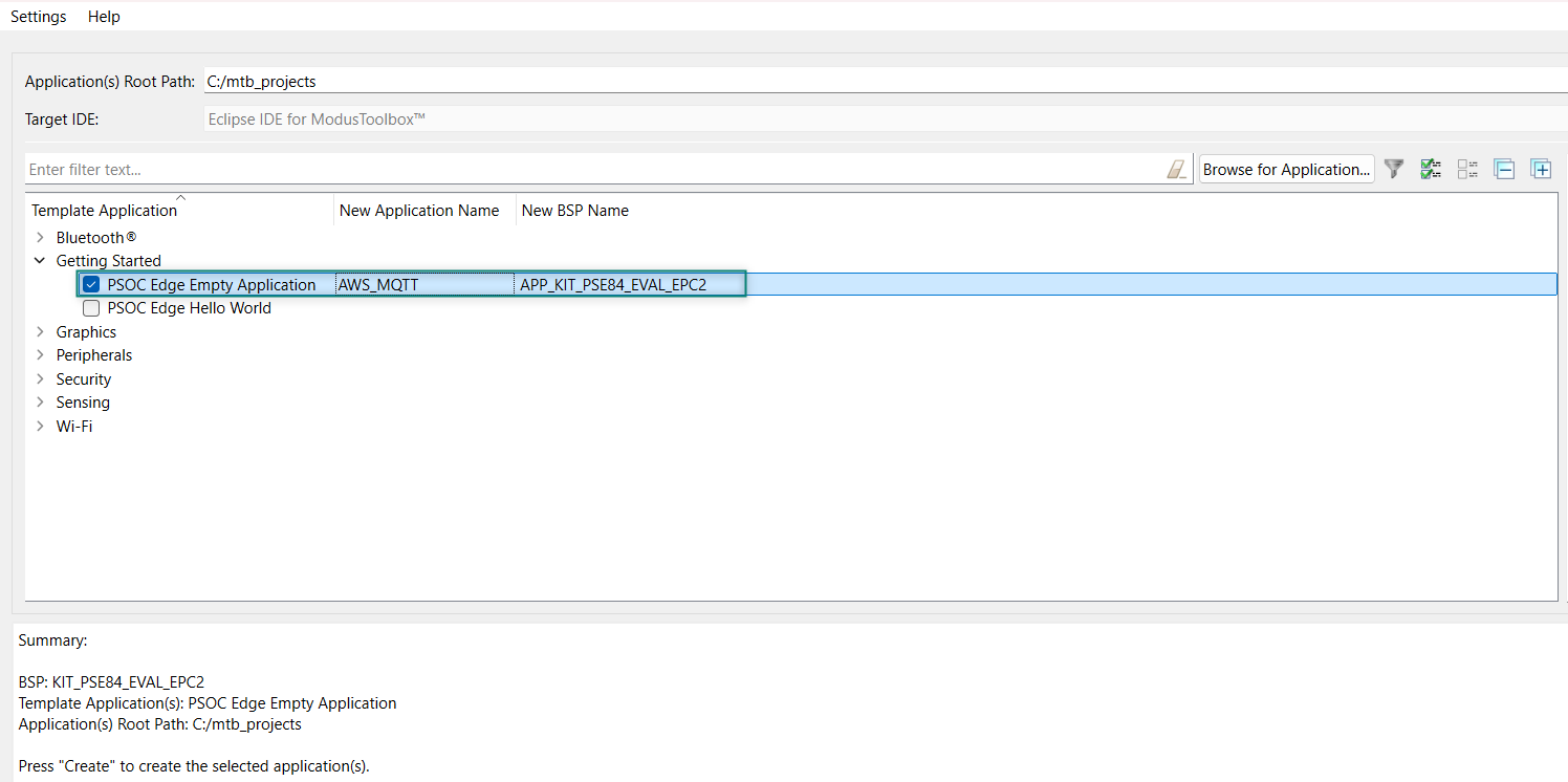
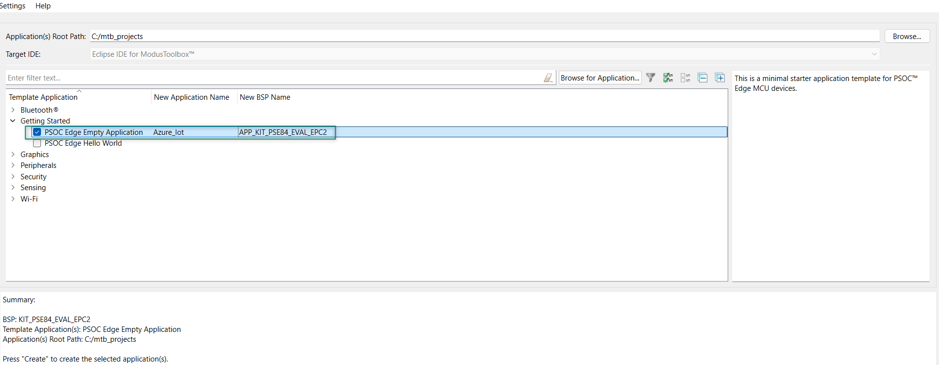
To create an Empty_app, select
PSOC Edge Empty Application
as shown in
Figure 19
In the
Name Application Name
field, type a required name for the application if required and click
Next
; the application summary dialog appears
Click
Create
and wait for the application to download and create in the workspace
Click
Close
to complete the application creation process. Here, the application is named as
AWS_MQTT
as shown in
Figure 19
Figure 19.
Create PSOC™ Edge Empty Application
You have successfully created a new ModusToolbox™ application for the PSOC™ Edge E84 MCU.
Configure design resources
In this step, you will configure the design resources for your application and generate the configuration code. You will also be adding the required middleware libraries.
Add libraries and middleware
ModusToolbox™ provides a Library Manager tool to select various middleware components for developing applications.
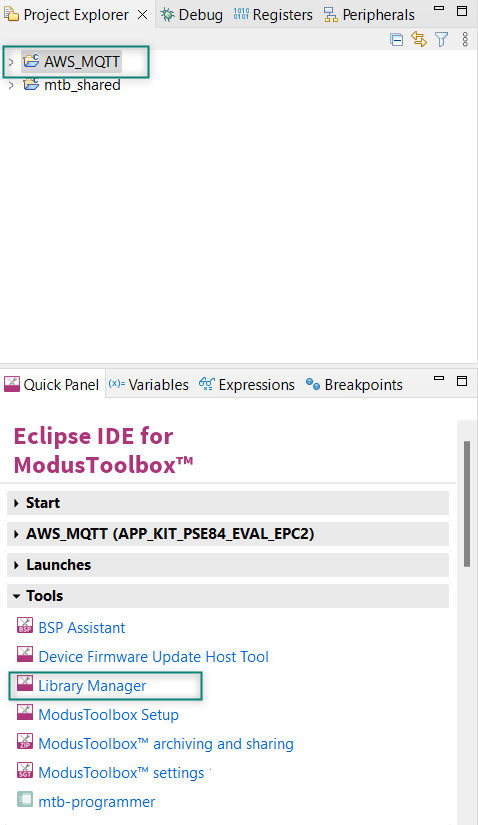
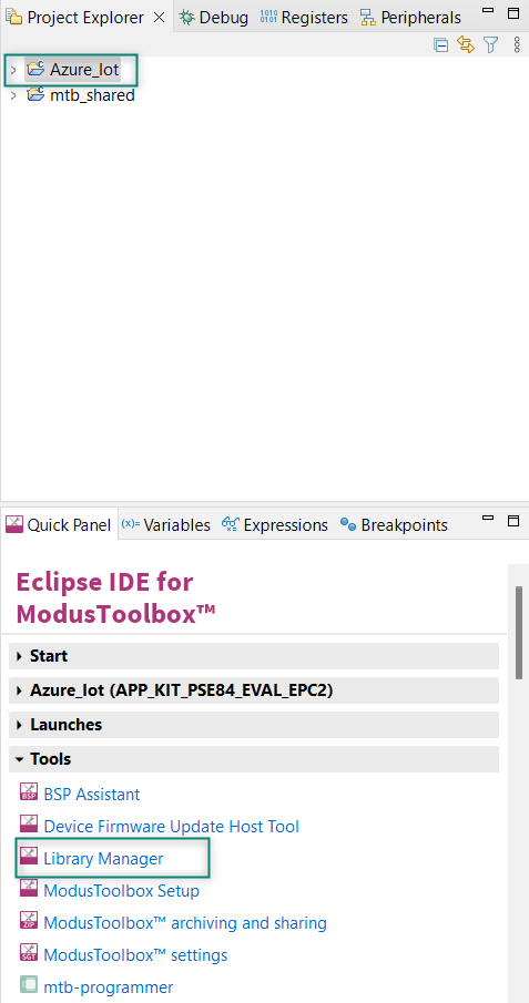
To launch the Library Manager, select the
AWS_MQTT
application, the application name will vary based on the name you provide while creating the empty_app and in the Quick Panel, click
Library Manager
as shown in
Figure 20
. Click Add Library to add the required libraries and middleware for your application.
Figure 20.
Open Library Manager
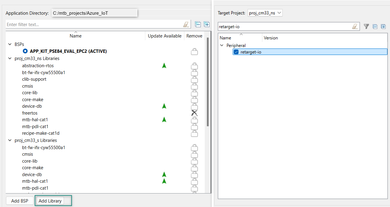
For the AWS_MQTT code example design, follow these steps to add the required libraries:
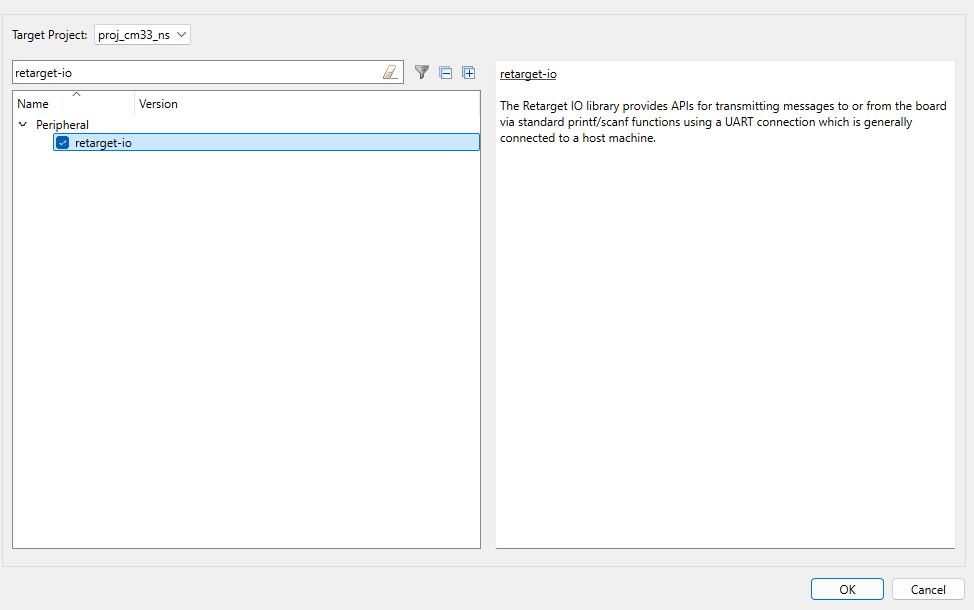
Add the retarget-io middleware to redirect the standard input and output streams to the UART configured by the BSP. The initialization of the middleware will be done in
main.c
file. Click Add Library, select proj_cm33_ns the target project and search the library name
retarget-io
in the
Enter filter text box.
For more information about the library, Refer the website
Retarget-io
.
Figure 21.
Add retarget-io library
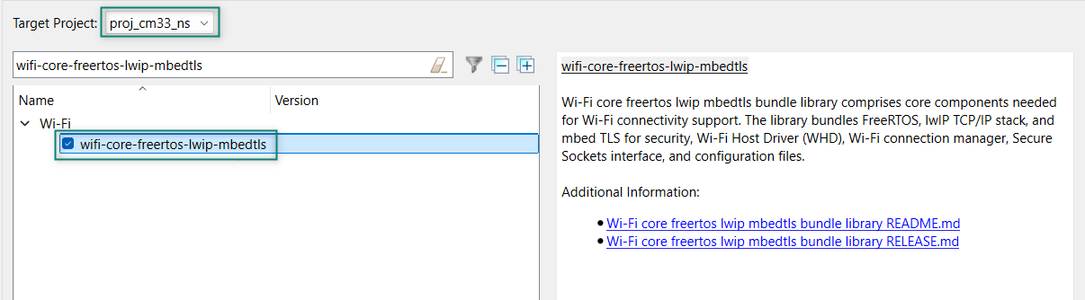
Add the wifi-core-freertos-lwip-mbedtls library. This bundle library comprises core components needed for Wi-Fi connectivity support. It bundles FreeRTOS, lwIP TCP/IP stack, and mbed TLS for security, Wi-Fi Host Driver (WHD), Wi-Fi Connection Manager, Secure Sockets interface, and configuration files. Click Add Library, select proj_cm33_ns as the Target Project, and select
, see
Figure 22
Figure 22.
Add wifi-core-freertos-lwip-mbedtls library
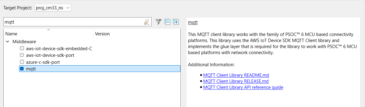
Add the MQTT Library as this library supports multi-core architecture by making a subset of APIs available as virtual APIs
Figure 23.
Add MQTT Library
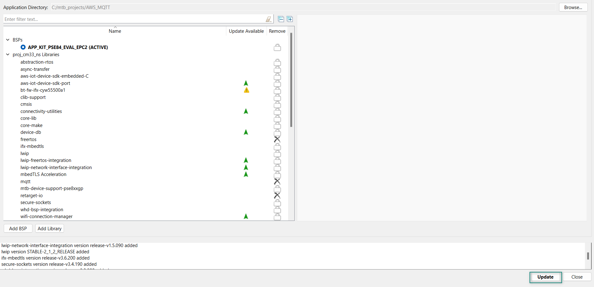
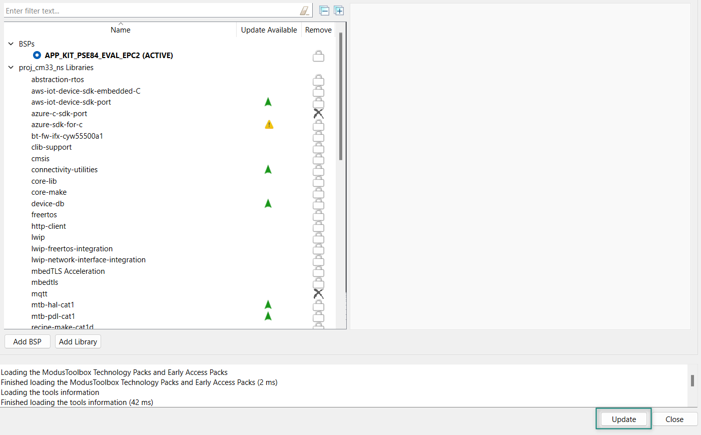
After selecting all the libraries, click
OK
and
Update
as shown in
Figure 24
Figure 24.
Update libraries
Write the application code
At this point in the development process, you created an application and added the required libraries. This part examines the application code that implements the AWS_MQTT code example.
Note:
The empty application of the PSOC™ Edge E84 MCU has a three project structure (proj_cm33_ns, proj_cm33_s, and proj_cm55). The application code of the AWS_MQTT example is to be written on the proj_cm33_ns project that uses the M33 core and subsequently the proj_cm55 project that uses the M55 core is put to Deep Sleep mode.
Add files to your project (required only for the Working from Scratch flow).
Visit the website, mtb-example-psoc-edge-wifi-mqtt-client which contains the application files that can be downloaded.
Copy the following folders from the mtb-example-psoc-edge-wifi-mqtt-client code example under proj_cm33_ns to your proj_cm33_ns folder of the Empty_App inside the ModusToolbox™ workspace folder, which contains:
File name | File definitions |
|---|---|
main.c | This is the source code for the MQTT Client example running on a CM33 CPU. |
core_mqtt_config.h | This file contains the configuration macros for the MQTT library. |
mbedtls_user_config.h | This file is part of the mbed TLS Library. |
mqtt_client_config.c | This file contains the configuration structures used by the MQTT client for MQTT connect operation. |
mqtt_client_config.h | This file contains all the configuration macros used by the MQTT client in this example. |
mqtt_task.c | This file contains the task that handles initialization and connection of Wi-Fi and the MQTT client. The task then starts reconnection mechanisms to handle Wi-Fi and MQTT disconnections. The task also handles all the cleanup operations to gracefully terminate the Wi-Fi and MQTT connections in case of any failure. |
mqtt_task.h | This file is the public interface of mqtt_task.c file. |
publisher_task.c | This file contains the task that sets up the user button GPIO for the publisher and publishes MQTT messages on the topic MQTT_PUB_TOPIC to control a device that is actuated by the subscriber task. The file also contains the ISR that notifies the publisher task about the new device state to be published. |
publisher_task.h | This file is the public interface of publisher_task.c file. |
subscriber_task.c | This file contains the task that initializes the user LED GPIO, subscribes to the topic MQTT_SUB_TOPIC, and actuates the user LED based on the notifications received from the MQTT subscriber callback. |
wifi_config.h | This file contains the configuration macros required for the Wi-Fi connection. |
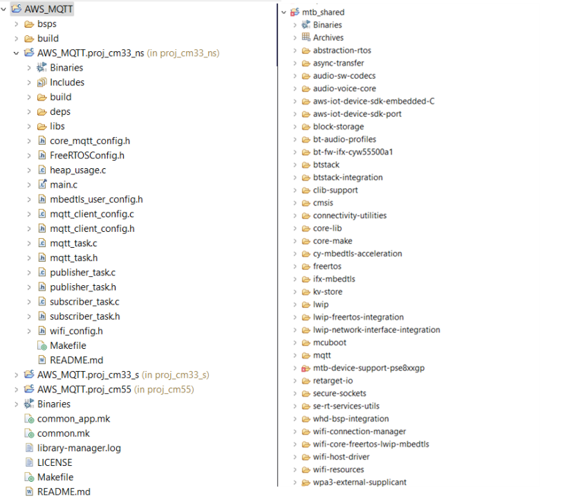
All PSOC™ Edge E84 MCU applications have a dual-CPU three-project structure to develop code for the CM33 and CM55 cores. The CM33 core has two separate projects for the Secure Project Environment (SPE) and Non-Secure Project Environment (NSPE). A project folder consists of various subfolders, each denoting a specific aspect of the project. See
Figure 25
for the final project structure.
Figure 25.
Project structure
Follow the steps from
AWS credential setup
to setup the AWS Things, MQTT broker, and generate a certificate.
Wi-Fi configuration:
Set the Wi-Fi credentials in
wifi_config.h
: Modify the macros
WIFI_SSID
,
WIFI_PASSWORD
, and
WIFI_SECURITY
to match with that of the Wi-Fi network that you want to connect.
MQTT configuration:
Some of the important configuration macros are as follows:
MQTT_BROKER_ADDRESS:
Hostname of the MQTT broker
MQTT_PORT:
Port number to be used for the MQTT connection. As specified by the Internet Assigned Numbers Authority (IANA), the port numbers assigned for the MQTT protocol are 1883 for non-secure connections and 8883 for secure connections. However, MQTT brokers can use other ports. Configure this macro as specified by the MQTT broker
MQTT_SECURE_CONNECTION:
Set this macro to '1' if a secure (TLS) connection to the MQTT broker is required to be established; else '0'
MQTT_USERNAME and MQTT_PASSWORD:
User name and password for client authentication and authorization if required by the MQTT broker. However, note that this information is generally not encrypted and the password is sent in plain text. Therefore, this is not a recommended method of client authentication
CLIENT_CERTIFICATE and CLIENT_PRIVATE_KEY:
Certificate and private key of the MQTT client used for client authentication. Note that these macros are applicable only when MQTT_SECURE_CONNECTION is set to '1'
ROOT_CA_CERTIFICATE:
Root CA certificate of the MQTT broker
Set up the MQTT client and configure the credentials in
mqtt_client_config.h
file.
In the
mqtt_client_config.h
file, set MQTT_BROKER_ADDRESS to your custom endpoint on the
Settings
page of the AWS IoT console. This has the format
ABCDEFG1234567.iot.<region>.amazonaws.com
Set the macros
MQTT_PORT
to
8883
and
MQTT_SECURE_CONNECTION
to
1
in the
mqtt_client_config.h
file
Download the following certificates and keys that are created and activated in the earlier step:
A certificate for the AWS IoT Thing:
xxxxxxxxxx.cert.pem
A public key:
xxxxxxxxxx.public.key
A private key:
xxxxxxxxxx.private.key
Root CA RSA 2048 bit key:
Amazon Root CA 1 for AWS IoT from
CA certificates for server authentication
Using these certificates and keys, enter the following parameters in
mqtt_client_config.h
file in Privacy-Enhanced Mail (PEM) format:
CLIENT_CERTIFICATE
:
xxxxxxxxxx.cert.pem
CLIENT_PRIVATE_KEY
:
xxxxxxxxxx.private.key
ROOT_CA_CERTIFICATE
: Root CA certificate
They must be formatted as shown in
Figure 26
.
Figure 26.
Certificate format
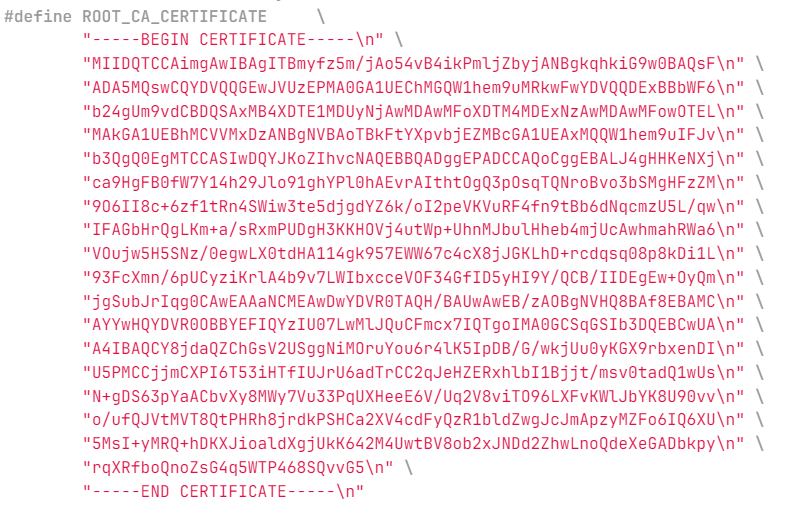
You can manually format the strings as shown in
Figure 26
or use
format_aws_certificates.py
to format each files one at a time. To use it:
Place the
format_aws_certificates.py
and certificates/keys in the same folder
Open modus-shell, go to the folder with the script and enter the following:
python ./format_certificates.py<filename>
Copy and paste the formatted strings from the output window to the proper locations in
mqtt_client_config.h
file
For a complete list of configuration macros used in this code example are as follows:
Wi-Fi connection configurations | In wifi_config.h file. |
| SSID of the Wi-Fi AP to which the MQTT client connects. |
| Security type of the Wi-Fi AP. See structure in the cy_wcm.h file for details. |
| Maximum number of retries for Wi-Fi connection. |
| Time interval in milliseconds in between successive Wi-Fi connection retries |
MQTT connection configurations | In mqtt_client_config.h file. |
MQTT connection configurations | Hostname of the MQTT broker. |
| Port number to be used for the MQTT connection. As specified by the IANA, the port numbers assigned for the MQTT protocol are 1883 for non-secure connections and 8883 for secure connections. However, MQTT brokers can use other ports. Configure this macro as specified by the MQTT broker. |
| Set this macro to '1' if a secure (TLS) connection to the MQTT broker is required to be established; else '0'. |
| User name and password for client authentication and authorization if required by the MQTT broker. However, note that this information is generally not encrypted and the password is sent in plain text. Therefore, this is not a recommended method of client authentication. |
MQTT client certificate configurations | In mqtt_client_config.h file. |
| Certificate and private key of the MQTT client used for client authentication. Note that these macros are applicable only when is set to '1'. |
| |
| Root CA certificate of the MQTT broker. |
MQTT message configurations | In mqtt_client_config.h file. |
| MQTT topic to which the messages are published by the publisher task to the MQTT broker. |
| MQTT topic to which the subscriber task subscribes to. The MQTT broker sends the messages to the subscriber that are published in this topic (or equivalent topic). |
| The Quality of Service (QoS) level to be used by the publisher and subscriber. Valid choices are '0', '1', and '2'. |
| Set this macro to '1' if you want to use the 'Last Will and Testament (LWT)' option; else '0'. LWT is an MQTT message that will be published by the MQTT broker on the specified topic if the MQTT connection is unexpectedly closed. This configuration is sent to the MQTT broker during MQTT connect operation; the MQTT broker will publish the Will message on the Will topic when it recognizes an unexpected disconnection from the client. |
| The MQTT topic and message for the LWT option described earlier. These configurations are applicable only when is set to '1'. |
| |
| The MQTT messages that control the device (LED) state in this code example. |
| |
Other MQTT client configurations | In mqtt_client_config.h file. |
| Every active MQTT connection must have a unique
client identifier. If this macro is set to '1', the device will generate
a unique client identifier by appending a timestamp to the string
specified by the |
| The client identifier (client ID) string to be used
during an MQTT connection. If |
| The longest client identifier that an MQTT server must accept (as defined by the MQTT 3.1.1 specification) is 23 characters. However, some MQTT brokers support longer client IDs. Configure this macro as per the MQTT broker specification. |
| Timeout in milliseconds for MQTT operations in this example. |
| The keepalive interval in seconds used for the MQTT ping request. |
| The application layer protocol negotiation (ALPN) protocol name to be used that is supported by the MQTT broker in use. Note that this is an optional macro for most of the use cases. Per IANA, the port numbers assigned for the MQTT protocol are 1883 for non-secure connections and 8883 for secure connections. In some cases, there is a need to use other ports for MQTT like port 443 (which is reserved for HTTPS). ALPN is an extension to TLS that allows many protocols to be used over a secure connection. |
| The server name indication (SNI) hostname to be used during the transport layer security (TLS) connection as specified by the MQTT broker. SNI is an extension to the TLS protocol. As required by a few MQTT brokers, SNI typically includes the hostname in the "Client Hello" message sent during a TLS handshake. |
| A network buffer is allocated for sending and
receiving MQTT packets over the network. Specify the size of this buffer
using this macro. Note that the minimum buffer size is defined by the |
| Maximum number of retries for MQTT connection. |
| Time interval in milliseconds in between successive MQTT connection retries. |
User application code entry
In this example, the MQTT client RTOS task establishes a connection with the configured MQTT broker and creates two tasks: publisher and subscriber. The publisher task publishes messages on a topic when the user button is pressed on the kit. The subscriber task subscribes to the same topic and controls the user LED1 based on the messages received from the MQTT broker. If the MQTT or Wi-Fi connection is lost, the application will automatically try to reconnect.
Operation as follows:
User button is pressed
GPIO interrupt service routine (ISR) notifies the publisher task
Publisher task publishes a message on a topic
MQTT broker sends back the message to the MQTT client because it is also subscribed to the same topic
When the message is received, the subscriber task turns the User LED1 ON or OFF. As a result, the user LED toggles every time when you press the User button1
Build, program, and test your design
This section shows how to build, program,
and test the Wi-Fi MQTT Client application on the KIT_PSE84_EVAL_EPC2. At this
point, it is assumed that you have followed the previous steps in this application
note to develop the Wi-Fi MQTT Client code example.
Note:
To understand the build and program process of a simpler application, see the
AN235935 - Getting started with PSOC™ Edge E8 MCU on ModusToolbox™ software
application note that explains how to run a simple hello world application on the KIT_PSE84_EVAL_EPC2.
To build, program, and test the application, do the following:
Connect the kit to your PC using the provided USB cable
The USB-to-UART serial interface on the kit provides access to the UART interface of the KIT_PSE84_EVAL_EPC2 device. Use your favorite serial terminal application (Tera Term is used in this design) and connect to the USB-to-UART serial port. Configure the terminal application to access the serial port using the following settings:
Baud rate: 115200 bps; Data: 8 bits; Parity: None; Stop: 1 bit; Flow control: None; New line for receiving data: Line Feed (LF) or auto setting
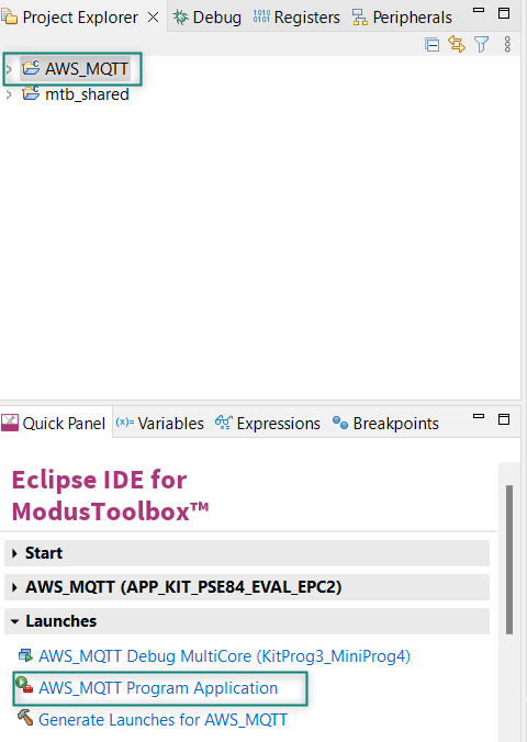
Build and program the application: In the Project Explorer, select the project. In the Quick Panel, scroll to the Launches section, and click the Program (KitProg3_MiniProg4) configuration as shown in
Figure 27
Figure 27.
Program the application
You can also use the command-line interface (CLI) to build and program the application. See the Build system chapter in the
ModusToolbox™ tools package user guide
After programming, the application starts automatically. Confirm that the text as shown in either one of the following figures is displayed on the UART terminal. Note that the Wi-Fi SSID and the IP address assigned will be different, based on the network that you have connected to
Figure 28.
Application initialization
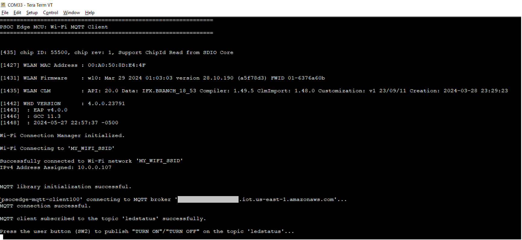
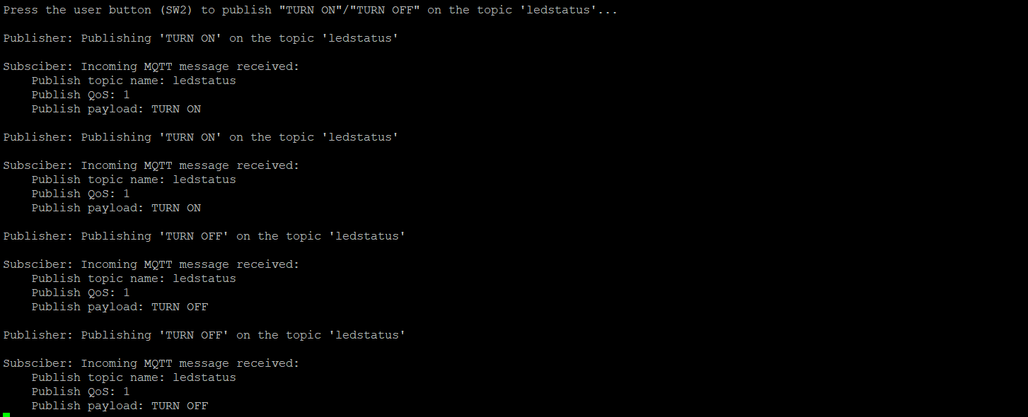
After the initialization is complete, confirm that the message
Press the user button (SW2) to publish "TURN ON"/"TURN OFF" on the topic 'ledstatus'
is printed on the UART terminal. This message may vary depending on the MQTT topic and publish messages that are configured in the
mqtt_client_config.h
file
Press the user button1 (SW2) on the kit to toggle the user LED1 state
Confirm that the user LED1 state is toggled and the messages received on the subscribed topic are printed on the UART terminal
Figure 29.
Publish subscribe messages
This example can be programmed on multiple kits (only when
GENERATE_UNIQUE_CLIENT_ID
is set to '1'); the user LEDs on all the kits will synchronously toggle with button presses on any kit
Alternatively, the publish and subscribe functionalities of the MQTT client can be individually verified if the MQTT broker supports a test MQTT client like the AWS IoT
To verify the subscribe functionality, use the test MQTT client, publish messages such as "TURN ON" and "TURN OFF" on the topic specified by the
MQTT_PUB_TOPIC
macro in
mqtt_client_config.h
file to control the LED state on the kit
To verify the publish functionality, from the Test MQTT client, subscribe to the MQTT topic specified by the
MQTT_SUB_TOPIC
macro and confirm that the messages published by the kit (when the user button is pressed) are displayed on the test MQTT client's console
Getting started with Azure communication
Azure credential setup
Azure IoT Hub is a managed service offered by Microsoft within the Azure Cloud Platform. It acts as a central hub for communication between millions of internet-connected devices (referred to as "things" on the Internet of Things or IoT) and cloud-based applications.
Azure IoT Hub seamlessly integrates with other Azure services like Azure Stream Analytics, Azure Machine Learning, and Azure Functions; allowing you to build powerful IoT solutions that analyze device data, generate insights, and automate actions based on real-time information.
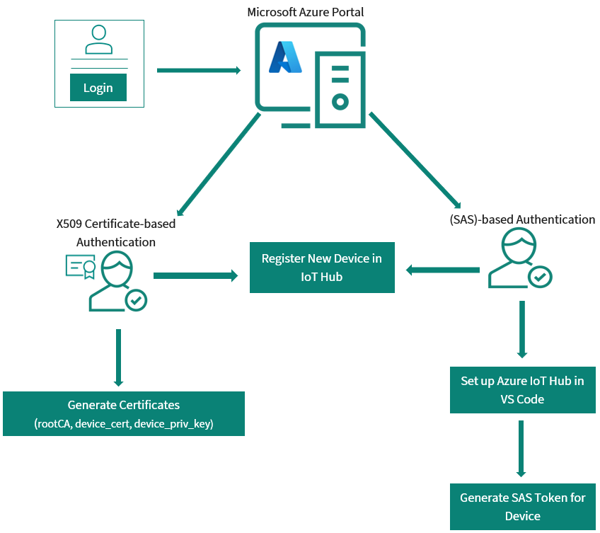
Figure 30.
Azure authentication process
Azure Hub setup
This section describes how to create an IoT hub using the
Azure portal
.
Sign in to
Azure portal
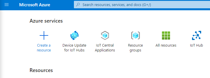
On the Azure homepage, select + Create a resource in the Azure services
Figure 31.
Create resource
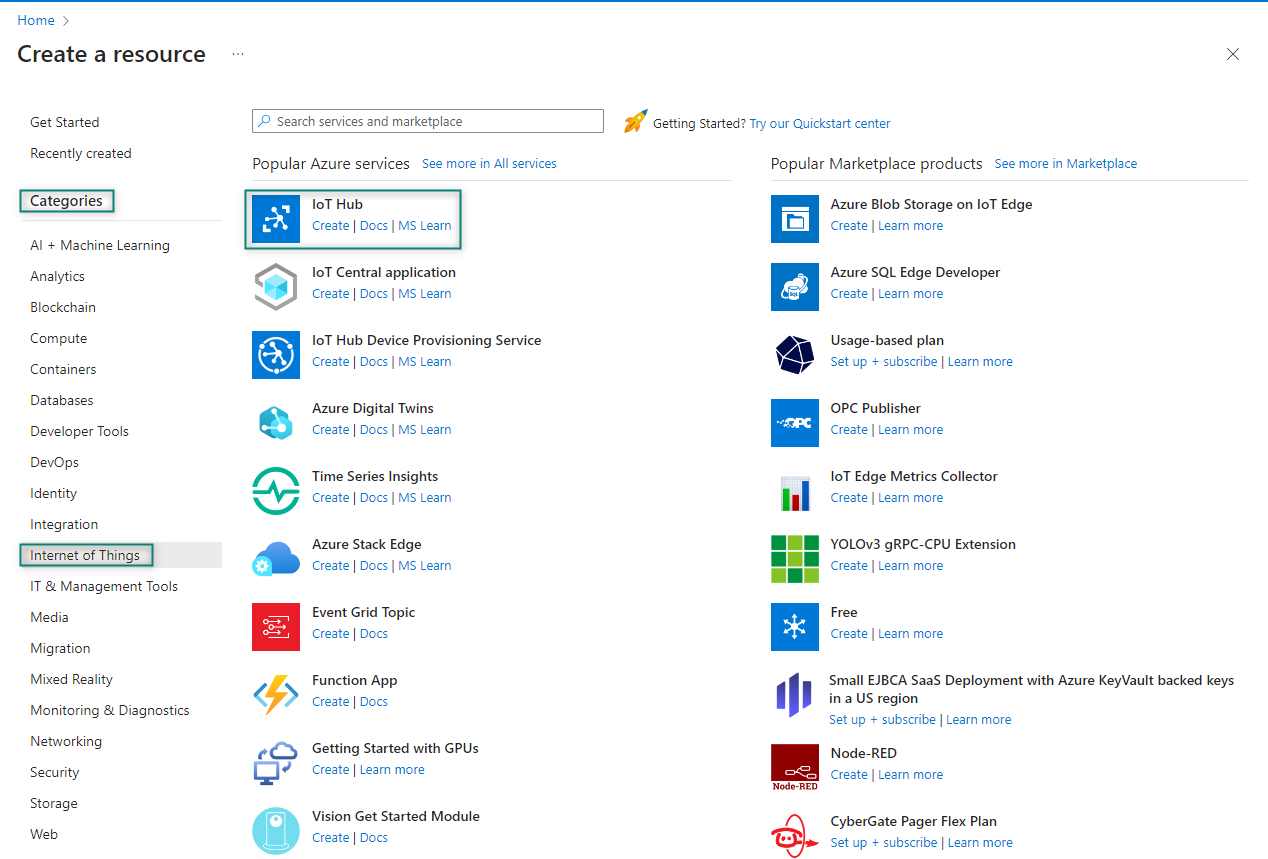
From the
Categories
, select
Internet of Things
, and then select
IoT Hub
Figure 32.
Select category
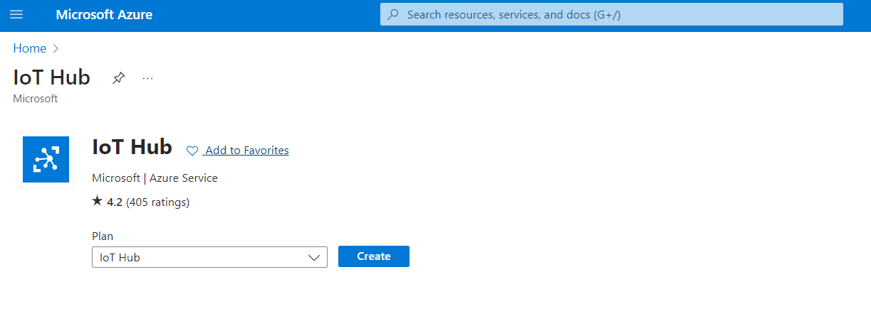
Click
Create
in the IoT Hub page
Figure 33.
IoT Hub
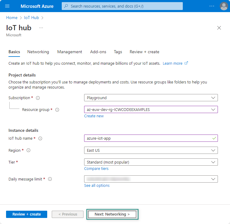
On the
Basics
tab, select the required fields as shown in
Figure 34
and click
Next: Networking >
Figure 34.
IoT Hub Basics details
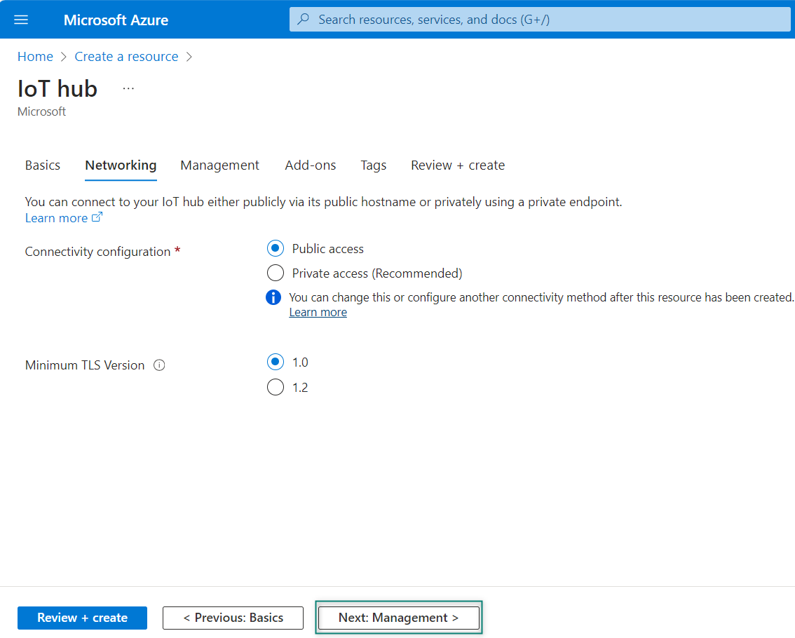
On the Networking tab, select the required fields as shown in
Figure 35
and select the TLS version as 1.2 if you are using the latest Baltimore root.ca certificate, and click
Next: Management >
Figure 35.
IoT Hub Networking details
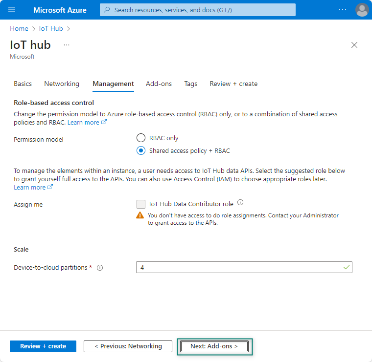
On the Management tab, use the default settings as shown in
Figure 36
. If required, you can modify any of the fields. Later, click on
Next: Add-ons >
to continue to the next page
Figure 36.
IoT Hub Management details
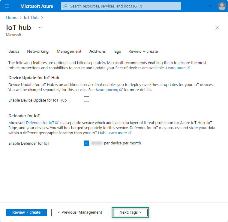
On the
Add-ons
tab, use the default settings as shown in
Figure 37
. If required, you can modify any of the fields and then click
Next: Tags >
Figure 37.
IoT Hub Add-ons details
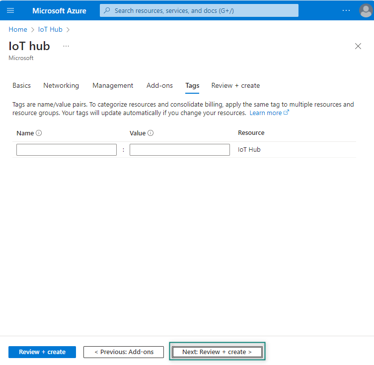
On the Tags tab, you can leave the fields empty if you do not need to add any name/value pairs as shown in
Figure 38
Figure 38.
IoT Hub Tags details
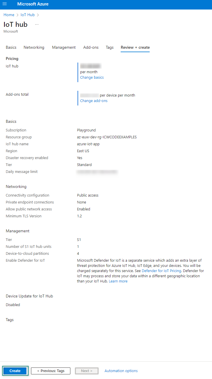
Select
Next: Review + create
to review your choices
Select
Create
to start the deployment of your new hub. Your deployment will be in progress a few minutes while the hub is being created. After the deployment is complete, select Go to resource to open the new hub
Figure 39.
IoT Hub Review details
If you require additional updates, see
Create and manage Azure IoT hubs
.
There are two ways to setup the X509 or SAS credentials-based on the hardware for the Azure IoT Hub that is explained in detail in the following section.
Shared access signature (SAS)-based authentication mode
Shared Access Signature (SAS) token functions as a digital keycard, granting controlled access to specific Azure resources for a limited duration. This approach ensures security by providing granular access permissions.
The following steps are used to generate the output of the
Azure Device App (C2D, Telemetry, Methods, Device Twin)
and
PnP (Plug and Play)
menu options of the ModusToolbox™ application.
Create a SAS authentication-based device on the Azure IoT Hub by following these steps:
Register a new device in the IoT Hub
In this section, you create a device identity in the identity registry in your IoT hub. A device cannot connect to a hub unless it has an entry in the identity registry. For more information, see the
IoT Hub developer guide
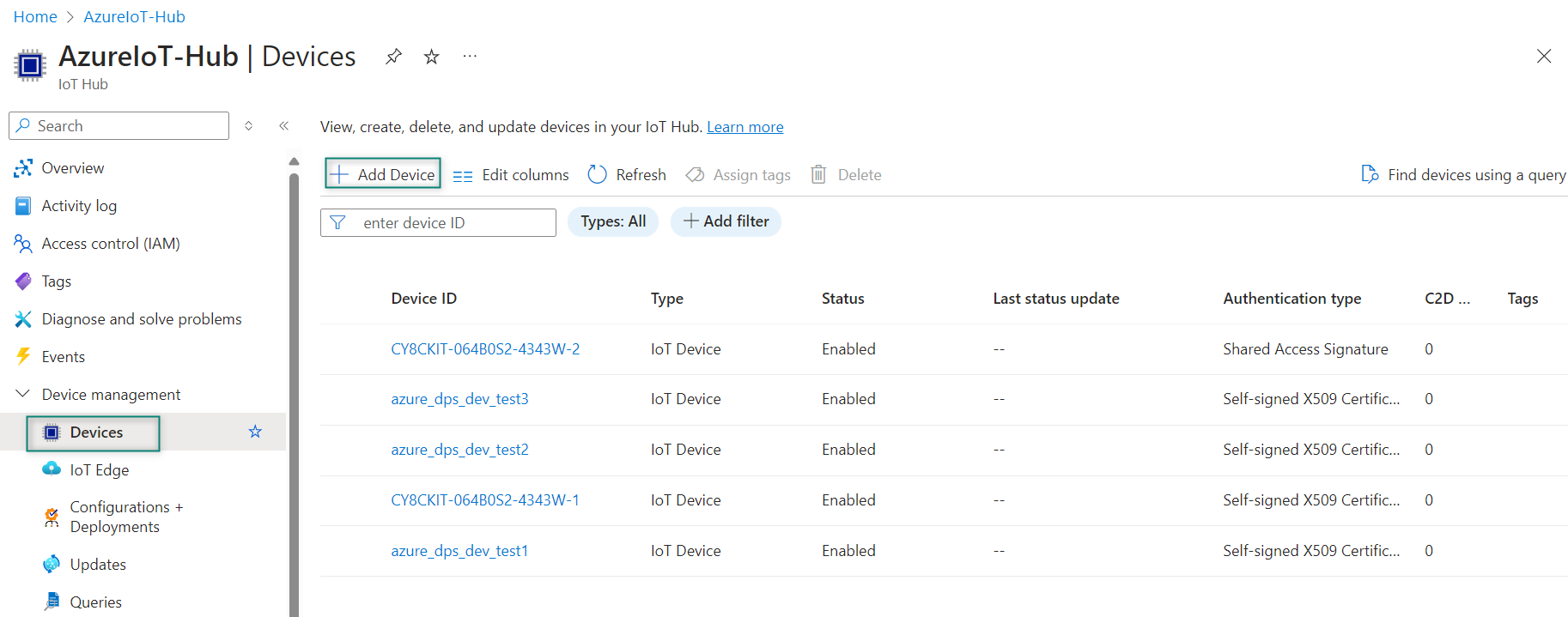
In your IoT hub navigation menu, open
Devices
, select
Add Device
as shown in
Figure 40
to add a device in your IoT hub created in
Azure Hub setup
Figure 40.
Add Device
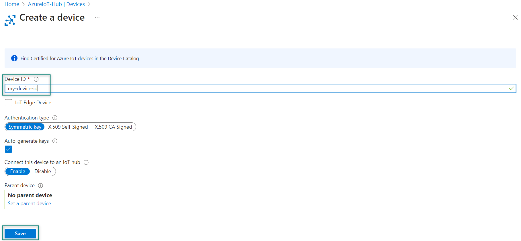
In
Create a device
, provide a name for your new device, such as
my-device-id
, and select
Save
as shown in
Figure 41
. It creates a device identity for your IoT hub. Select
Auto-generate keys
so that the primary and secondary keys will be generated automatically
Figure 41.
Add Device ID
Click
Save
. After creating the device, open the device from the list in the
Devices
pane. Copy the value of the
Primary connection string
. This connection string is used by device code to communicate with the IoT hub
Figure 42.
Device ID details
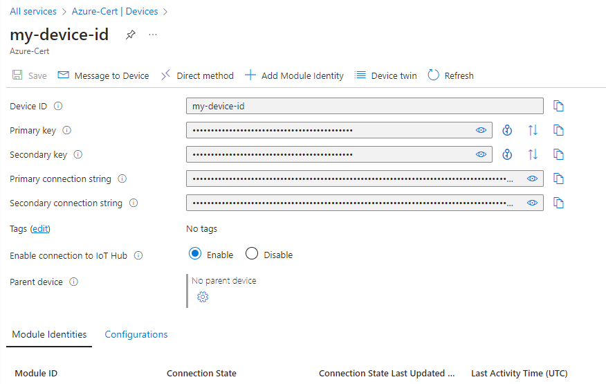
By default, the keys and connection strings are masked because they are sensitive information as shown in
Figure 42
. Click the eye icon to reveal the password. It is not necessary to reveal them to copy them with the copy button
Visual Studio Code setup
Download and install
Visual Studio Code
if you do not have in the system
Azure IoT tools
Install
Azure IoT Hub
to connect it to Visual Studio
Set up your Azure IoT Hub in VS Code
Set up your Azure IoT Hub in VS Code after installation. You will see the device list to interact with your IoT hub and devices after setup
In Explorer of VS Code, click
Azure IoT Hub Devices
in the bottom-left corner
Click
Select IoT Hub
in the context menu
If you did not sign in to Azure, a pop-up will show to let you sign in to the Azure platform
After sign in, select your Azure subscription
Select your IoT Hub from the list
The device list will be displayed as shown in
Figure 43
Figure 43.
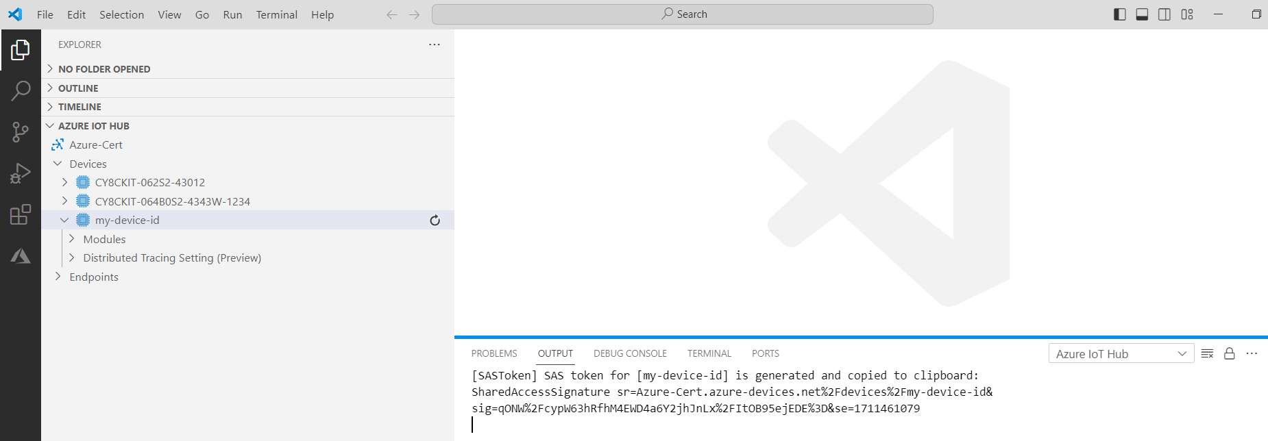
Generate SAS Token for Device
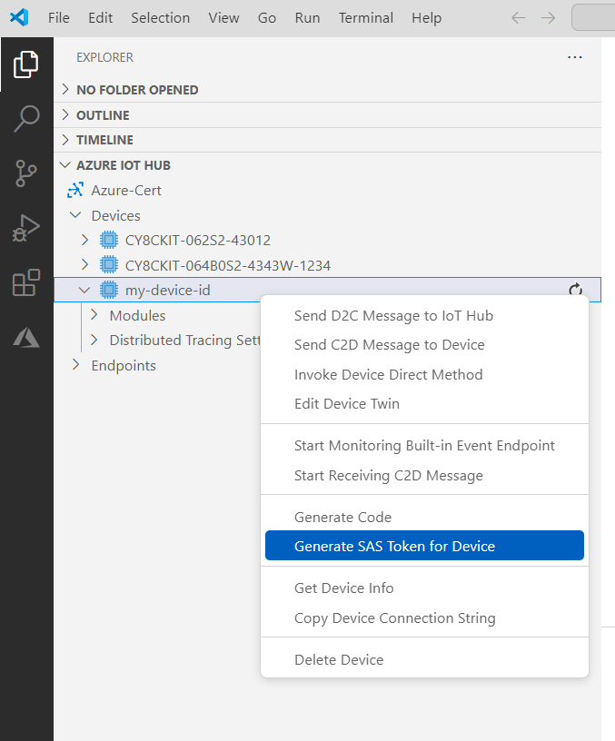
For SAS token generation, right-click your device and select
Generate SAS Token for Device
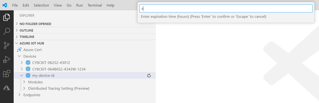
Enter the expiration time in hours as shown in
Figure 44
Figure 44.
Enter the expiration time
Copy the generated SAS token to the clipboard
Figure 45.
Copy the generated SAS token
X509 certificate-based authentication mode
Use the following steps to generate the device's X509 self-signed certificate and private key to setup the X509 authentication-based device on Azure IoT Hub
Create a certificates directory
Run the following command in the modus-shell in the certificates folder to generate the device private key.
openssl req -newkey rsa:2048 -nodes -keyout dev_priv_key.pem
To run this command, enter the additional information, as shown in the following example. The Common Name can be your choice but must match the registration ID on the Azure DPS portal's enrollment or the device ID on the Azure IoT Hub portal is created in the following steps:
The
A challenge password
and
An optional company
name fields are left blank.
Country Name (2 letter code) [XX]:USState or Province Name (full name) []:CALocality Name (e.g, city) [Default City]:SJOrganization Name (e.g, company) [Default Company Ltd]:IFXOrganizational Unit Name (e.g, section) []:INFINEONCommon Name (e.g, your name or your server's hostname) []:x509-certEmail Address []:Enter the following 'extra' attributes to be sent with your certificate request
A challenge password []:An optional company name []:Copy the
x509_config.cfg
file from the scripts folder to the
certificates
folder
Run the following command in the modus-shell in the
certificates
folder to generate the X.509 certificate.
Note:
The value of the common name field in the following command -
CN
can be your choice but must match the registration ID on the Azure DPS portal's enrollment or the device ID on the Azure IoT Hub portal is created as mentioned in the following steps:
openssl req -new -days 1024 -nodes -x509 -key dev_priv_key.pem -out device_cert.pem -extensions client_auth -config x509_config.cfg -subj "/CN=azure_dps_dev_test1"Run the following command in the modus-shell in the
certificates
directory to get the SHA thumbprint of the device certificate created in Step 3. Copy the fingerprint generated in the following command:
openssl x509 -noout -fingerprint -in device_cert.pem | sed 's/://g'| sed 's/\(SHA1 Fingerprint=\)//g'Example of a fingerprint from the previous command:
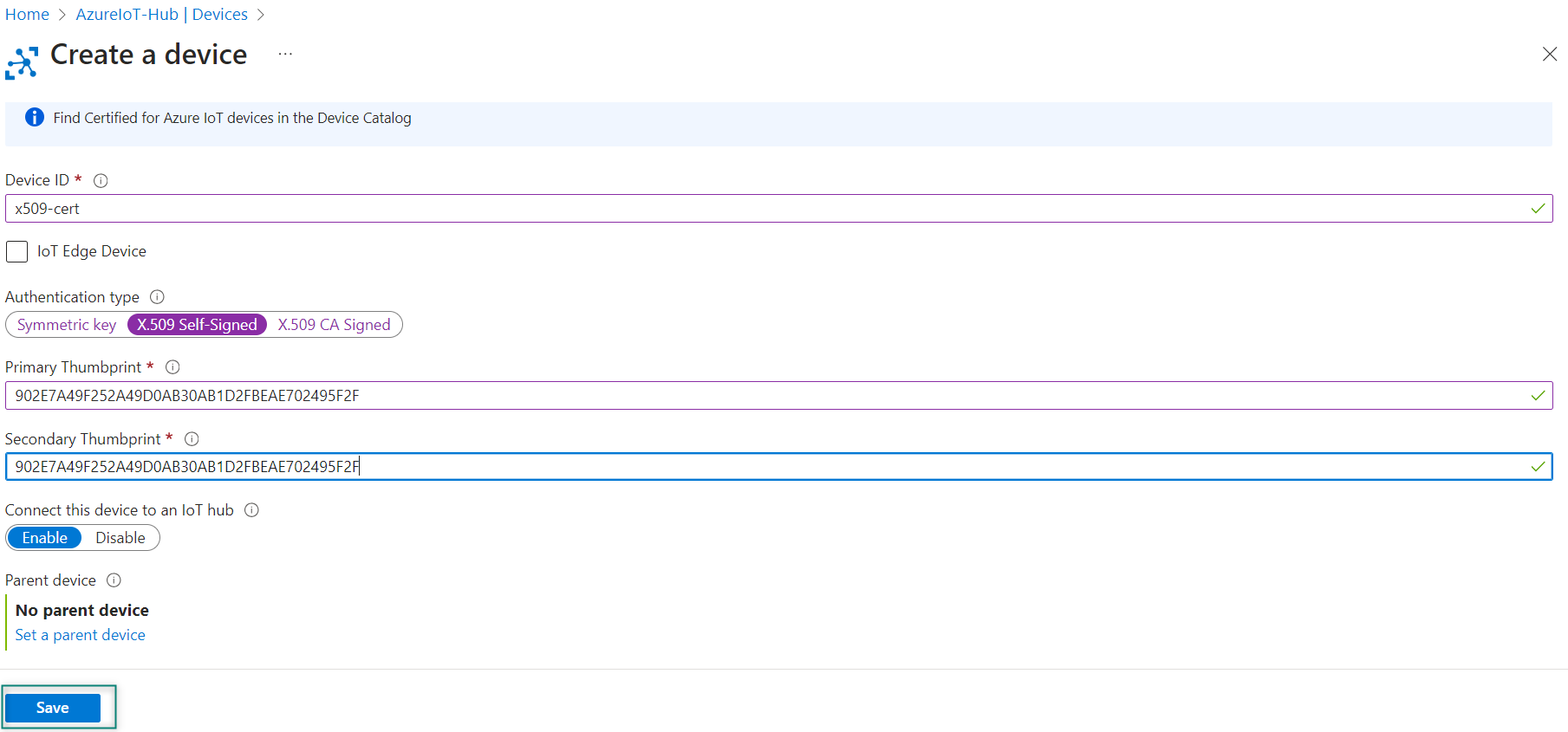
902E7A49F252A49D0AB30AB1D2FBEAE702495F2FFollow these steps to create a device in the IoT Hub created in
Azure Hub setup
. Ensure to give the same name for the
Device ID
that is given for the Common name. Use the fingerprint generated in Step 3 for both Primary Thumbprint and Secondary Thumbprint. Click
Save
as shown in
Figure 46
Figure 46.
Create a device
Download
DigiCertAssuredIDRootG2.pem
certificate and use the following command to convert the certificate from
.crt
to
.pem
. The out parameter must be
azure_rootCA.pem
openssl x509 -inform der -in DigiCertAssuredIDRootG2.crt -out azure_rootCA.pem
Note:
If the Azure IoT Device is configured to use the DigiCert Global G2 Root certificate, use the same
The
.pem
format of the certificates and keys needs to be used in the file. Use
scripts/format_X509_cert_key.py
to generate the formatted pem. Copy and paste this script in
certificates
folder and use it as follows:
python format_X509_cert_key.py azure_rootCA.pem device_cert.pem dev_priv_key.pemx
Connecting to Azure IoT services using Azure SDK for Embedded C
This section describes how to build an Azure IoT based application for PSOC™ Edge E84 device using Eclipse IDE for ModusToolbox™. It uses the Azure SDK for Embedded C library to connect the device with Azure.
Prerequisites
Before you start, ensure that you have the appropriate development kit for the PSOC™ Edge E84 MCU product line, and have installed the required software. See
Hardware and software requirements
for more details.
Application development
The following sections provide guidelines on how to develop an application:
Create a new application
View and modify the design
Develop your application
Build the application
Program the device
Test your design
Note:
This design is developed for the PSOC™ Edge E84 Evaluation Kit (KIT_PSE84_EVAL_EPC2).
About the design
This example implements two RTOS tasks to demonstrate Azure IoT Hub features: Cloud to Device (C2D), Telemetry, methods, Device Twin, and plug and play (PnP). The main function initializes the BSP and the retarget-io library and calls the Menu function which shows the list of Azure features. After selecting a feature, a task is created for running the feature. Every feature task requires valid certificates or tokens that need to be passed either from the flash or secured hardware.
After the validation of IoT device credentials, the data exchange can then take place between the Hub and the device.
SAS authentication
SAS tokens are generated using symmetric keys provided during device enrollment. The device then uses this key to generate SAS tokens. These SAS tokens have a hashed signature, which is used to verify the authenticity of these tokens. Once the device is authenticated, these SAS tokens are used to connect to the Azure IoT Hub and send messages.
X.509 authentication
X.509 certificate (Public Key Infrastructure) is used to authenticate devices to the IoT Hub and secure the IoT Hub endpoints. The process begins with registering and uploading the X.509 certificates to an IoT Hub which will be used for authentication of IoT devices to the IoT Hub whenever they connect. This authentication process saves from generating private secure keys for every IoT device. With the X.509 CA feature, you need to register the certificate once, and then use it to connect and authenticate as many devices as you want.
Create a new application
This section provides a step-by-step guideline for creating a new application. It uses the Empty App starter application and manually adds the functionality from the PSOC™ Edge MCU: Connecting to Azure IoT using Azure SDK for C application. The Eclipse IDE for ModusToolbox™ is used in the instructions, but you can use any IDE or the command-line tool if you prefer.
If you are familiar with developing projects with ModusToolbox™ software, you can use the
PSOC™ Edge MCU: Connecting to Azure IoT using Azure SDK for C
starter application directly for PSOC™ Edge and
Connecting to Azure IoT services using Azure SDK for Embedded C
for PSOC™ 6 application. It is a complete design with all the firmware written for the supported kits. You can walk through the instructions and observe how the steps are implemented in the code example.
Launch Eclipse IDE for ModusToolbox™ to get started. It requires the Internet connection to download the assets from GitHub repositories.
The following sections provide the steps to start with a new empty application.
Select a new workspace
At launch, Eclipse IDE for ModusToolbox™ shows a dialog box to choose a directory as the workspace directory. The workspace directory is used to store workspace preferences and development artifacts such as device configuration and application source code. You can choose an existing empty directory by clicking the
Browse
button. Alternatively, you can type in a directory name to be used as the workspace directory along with the complete path, and ModusToolbox™ will create the directory for you.
Figure 47.
Select a directory as workspace
Create a new ModusToolbox™ application
Click
New Application
in the Quick Panel. Alternatively, go to
and click ModusToolbox™ Application.
Figure 48.
Create a new ModusToolbox™ application
Select PSOC™ Edge E84 MCU-based target hardware
ModusToolbox™ lists the Infineon kits to start your application development. In this case, develop an application on the PSOC™ Edge E84 Evaluation Board that uses the PSOC™ Edge line device. Select KIT_PSE84_EVAL_EPC2 and click
Next
as shown in
Figure 49
.
Figure 49.
Choose target hardware
Select a PSOC™ Edge Empty application and create the application (applicable only for “Working from Scratch” flow)
Use an existing empty application as the starting point for the Working from Scratch development flow.
This is a minimal starter application template for PSOC™ Edge MCU devices. This example uses FreeRTOS to blink two LEDs with different frequencies respectively from the Arm® Cortex®-M33 CPU and the Arm® Cortex®-M55 CPU. This code example has a three project structure that is, CM33 secure, CM33 non-secure, and CM55 projects. All three projects are programmed to an external QSPI flash and executed in the XIP mode. Extended boot launches the CM33 secure project from a fixed location in an external flash, which then configures the protection settings and launches the CM33 non-secure application. Additionally, the CM33 non-secure application enables the CM55 CPU and launches the CM55 application.
The application code of
mtb-example-psoc-edge-azure-iot
uses only the CM33 CPU of the PSOC™ Edge E84 MCU. Therefore, the application is written under the CM33 non-secure project (proj_cm33_ns) and the CM55 CPU (in proj_cm55) is subsequently put to Deep Sleep mode.
To create an Empty_app, select
PSOC Edge Empty Application
as shown in
Figure 50
In the
Name Application Name
field, type a required name for the application if required and click
Next
; the application summary dialog appears
Click
Create
and wait for the application to download and create in the workspace
Click
Close
to complete the application creation process. Here, the application is named as
Azure_IoT
as shown in
Figure 50
Figure 50.
Create PSOC™ Edge Empty Application
You have successfully created a new ModusToolbox™ application for the PSOC™ Edge E84 MCU.
Configure design resources
In this step, you will configure the design resources for your application and generate the configuration code. You will also be adding the required middleware libraries.
Add libraries and middleware
ModusToolbox™ provides a Library Manager tool to select various middleware components for developing applications.
To launch the Library Manager, select the empty application. the application name will vary based on the name you provide while creating the empty_app and in the Quick Panel, click Library Manager as shown in
Figure 51
. Click Add Library to add the required libraries and middleware for your application.
Figure 51.
Open Library Manager
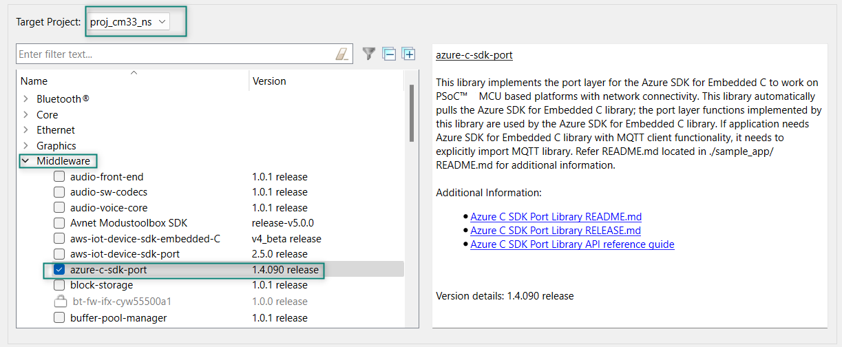
For the Azure_IoT code example design, follow these steps to add the required libraries:
Add the retarget-io middleware to redirect standard input and output streams to the UART configured by the BSP. The initialization of the middleware will be done in
main.c
file. Click Add Library, select proj_cm33_ns the target project and search the library name
retarget-io
in the
Enter filter text box.
You can find it under the peripheral section.
For more information about the library, Refer the website
Retarget-io
.
Figure 52.
Add retarget-io library
Add the wifi-core-freertos-lwip-mbedtls library. This bundle library comprises core components needed for Wi-Fi connectivity support. It bundles FreeRTOS, lwIP TCP/IP stack, and mbed TLS for security, Wi-Fi Host Driver (WHD), Wi-Fi Connection Manager, Secure Sockets interface, and configuration files. Click Add Library, select proj_cm33_ns as the Target Project and select
, see
Figure 53
Figure 53.
Add wifi-core-freertos-lwip-mbedtls library
Add the Azure-c-sdk-port library as this library is used as a port layer where it pulls the library Azure SDK for Embedded C to work with cloud connectivity applications.
Figure 54.
Add azure-c-sdk-port
Add MQTT library. It works with PSOC™ Edge and PSoC™ 6 MCU-based connectivity platforms. The library supports multi-core architecture by making a subset of APIs available as virtual APIs.
Figure 55.
Add MQTT Library
After selecting the required libraries, click
OK
and
Update
as shown in
Figure 56
Figure 56.
Update libraries
Write the application code
At this point in the development process, you created an application and added the required libraries. This part examines the application code that implements the Azure_IoT code example.
Note:
The empty application of the PSOC™ Edge E84 MCU has a three project structure (proj_cm33_ns, proj_cm33_s, and proj_cm55). The application code of the Azure_IoT example is to be written on the proj_cm33_ns project that uses the M33 core and subsequently the proj_cm55 project that uses the M55 core is put to Deep Sleep mode.
Operation as follows:
Visit the website,
PSOC™ Edge MCU: Connecting to Azure IoT using Azure SDK for C
which contains the application files that can be downloaded
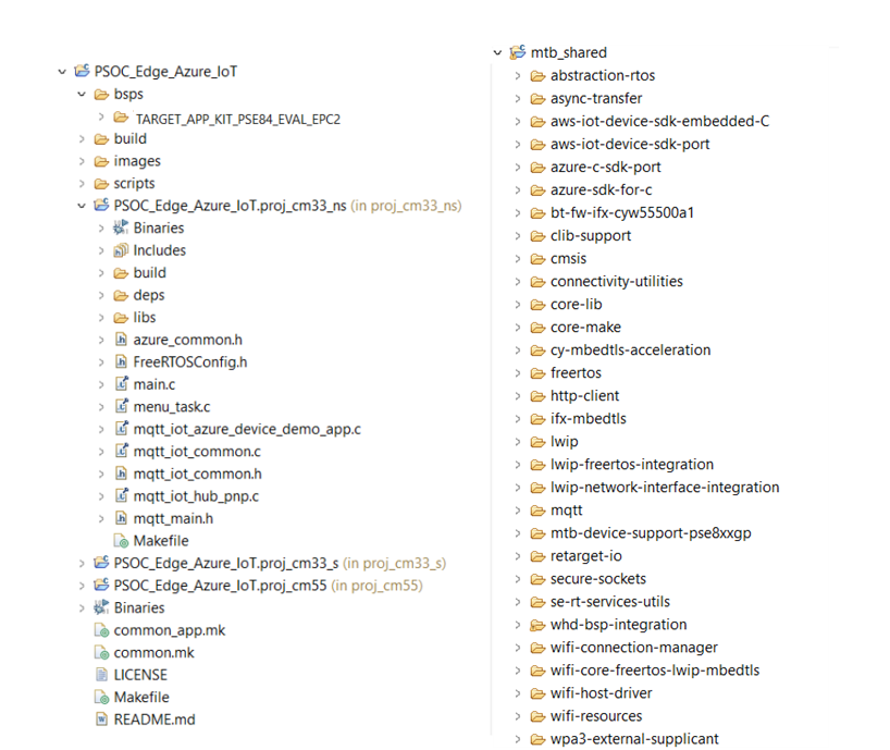
Copy the following folders from the
mtb-example-psoc-edge-azure-iot
code example under proj_cm33_ns to your proj_cm33_ns folder of the Azure_IoT inside the ModusToolbox™ workspace folder, which contains:
Table 3.
Code example files
File name
File definitions
main.c
This file contains the int main () function that is the entry point for execution of the user application code after device startup.
menu_task.c
This file contains tasks and functions related to Azure feature task creation and Wi-Fi initialization.
mqtt_iot_azure_device_demo_app.c
This file contains tasks and functions related to Azure device demo task.
mqtt_iot_common.c
This file contains implementation of utility functions for Azure sample applications on Infineon platforms.
mqtt_iot_common.h
This file contains header file for Azure sample applications utility functions on Infineon platforms.
mqtt_iot_hub_pnp.c
This file contains tasks and functions related to Azure Plug and Play feature task.
mqtt_main.h
Contains all the Azure IoT device configurations required by the Azure application.
azure_common.h
Contains all the common configurations required for the Azure application.
All PSOC™ Edge E84 MCU applications have a dual-CPU three-project structure to develop code for the CM33 and CM55 cores. The CM33 core has two separate projects for the Secure Project Environment (SPE) and Non-Secure Project Environment (NSPE). A project folder consists of various subfolders, each denoting a specific aspect of the project. See
Figure 57
of the code example project structure and libraries added
Figure 57.
Project structure
Follow the steps from
Azure Hub setup
to setup the Azure IoT Hub. There are two types of authentication modes: Shared Access Signatures (SAS) and X.509 certificates. SAS grants short-lived, granular access to Azure resources for applications. X.509 certificates provide strong, mutual authentication for users and services. Both are secured connections but SAS is simpler for resources, while X.509 is ideal for user authentication
Select either of the following methods for authentication of the Azure IoT device with the Azure Hub
Shared access signature (SAS)-based authentication mode
Set the
SAS_TOKEN_AUTH
macro to '1' in
source/azure_common.h
file
Use the following steps to generate the output of the
Azure Device App (C2D, Telemetry, Methods, Device Twin)
and
PnP (Plug and Play)
menu options of this ModusToolbox™ application
Create a SAS authentication-based device on the Azure IoT Hub by referring to
About the design
section
Generate a SAS token for the device using the following instructions as mentioned in
SAS token generation
. The VS Code's
Get device info
can be used for acquiring device information like the host name and device ID as shown in
Shared access signature (SAS)-based authentication mode
Update the files as follows in
source/azure_common.h
file
Set the
SAS_TOKEN_LOCATION_FLASH
macro as
true
Update the device ID in
MQTT_CLIENT_IDENTIFIER_AZURE_SAS
Update host name/hub name of the created IoT Hub in
IOT_DEMO_SERVER_AZURE
Update device ID in
IOT_AZURE_USERNAME
Update the generated SAS token in
IOT_AZURE_PASSWORD
These changes are required for to identify the specified IoT Hub that device needed to be connected to and provide device ID where the hub uses this ID to route the messages from the device
X509 certificate-based authentication mode
Follow these steps to generate the output of the
Azure Device App (C2D, Telemetry, Methods, Device Twin)
and
PnP (Plug and Play)
menu options of this ModusToolbox™ application
Create an X509-based device, it is a certificate and private key for Azure IoT Hub by referring to
X509 certificate-based authentication mode
In
source/mqtt_main.h
file update the following macros:
Update the device ID in the
MQTT_CLIENT_IDENTIFIER_AZURE_CERT
macro
Update the host name/hub name on which the device will be registered in macro
IOT_DEMO_SERVER_AZURE
Update the device ID in the
IOT_AZURE_USERNAME
macro
Update the pem format value of certificates and keys in the
azure_root_ca_certificate
,
azure_client_cert
, and
azure_client_key
as mentioned in the
Azure credential setup
section for a non-secure kit
Azure root ca certificate - Contains the public key of the Azure Root CA. When your device connects to Azure IoT Hub (or any Azure Service), it uses this certificate to verify that the certificates presented by Azure are genuine
Azure client certificate - X.509 client certificate containing your device's unique identity and signed by a trusted CA
Azure client key - Private key that goes with your device's certificate
Update the Wi-Fi details to the network that you want to connect to by changing the
WIFI_SSID
and
WIFI_PASSWORD
in the
source/mqtt_main.h
file
Build, program, and test your design
This section shows how to build, program,
and test the Azure IoT application on the KIT_PSE84_EVAL_EPC2. It also explains how
to run the Python script on the server side (your PC). At this point, it is assumed
that you have followed the previous steps in this application note to develop the
Azure IoT code example.
Note:
To understand the build and program process of a simpler application, see the
AN235935 - Getting started with PSOC™ Edge E8 MCU on ModusToolbox™ software
application note that explains how to run a simple hello world application on the KIT_PSE84_EVAL_EPC2.
To build, program, and test the application, do the following:
Connect the kit to your PC using the provided USB cable
The USB-to- UART serial interface on the kit provides access to the UART interface of the KIT_PSE84_EVAL_EPC2 device. Use your favorite serial terminal application (Tera Term is used in this design) and connect to the USB-to-UART serial port. Configure the terminal application to access the serial port using the following settings:
Baud rate: 115200 bps; Data: 8 bits; Parity: None; Stop: 1 bit; Flow control: None; New line for receiving data: Line Feed (LF) or auto setting
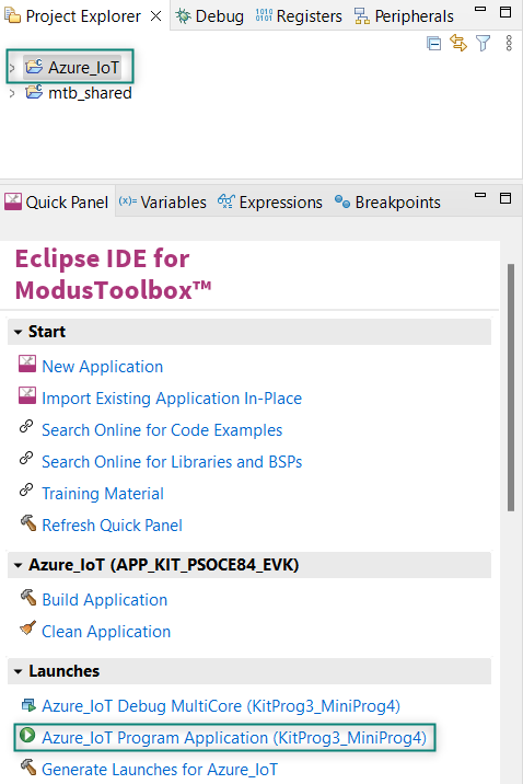
Build and program the application: In the Project Explorer, select the project. In the Quick Panel, scroll to the Launches section, and click the program (KitProg3_MiniProg4) configuration as shown in
Figure 58
Figure 58.
Program the application
Note:
You can also use the command-line interface (CLI) to build and program the application. See the Build system chapter in the
ModusToolbox™ tools package user guide
Code example output
After programming, the application starts automatically. Confirm that the text as shown in either one of the following figures is displayed on the UART terminal. Note that the Wi-Fi SSID and the IP address assigned will be different, based on the network that you have connected to.
Figure 59.
Application initialization
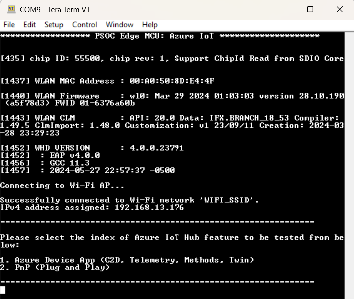
Select 1. to see the output for
Azure Device App
Select 2. to see the output for
PnP <Plug and Play>
Azure Device App
Cloud-to-device (C2D) messaging :
The
Azure Device App
receives the incoming C2D messages sent from the Azure IoT Hub to the device.
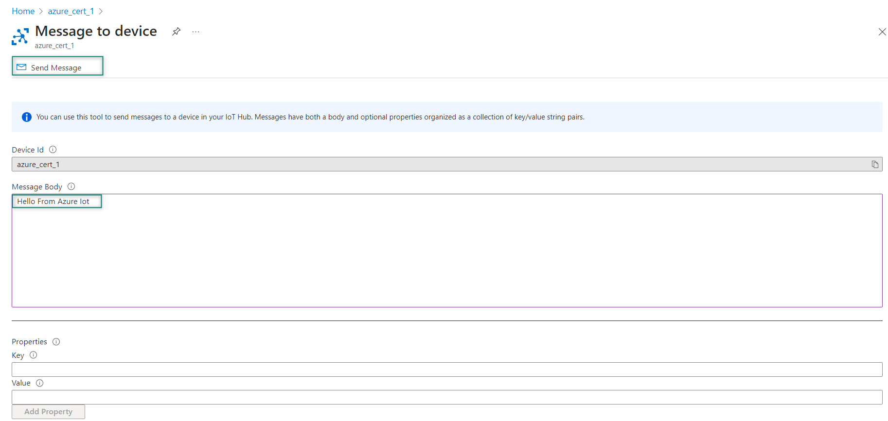
To send a C2D message, select your device's
Message to device
tab in the IoT Hub of the Azure portal. Enter a message in the
Message Body
and click
Send Message
.
Figure 60.
Message to device
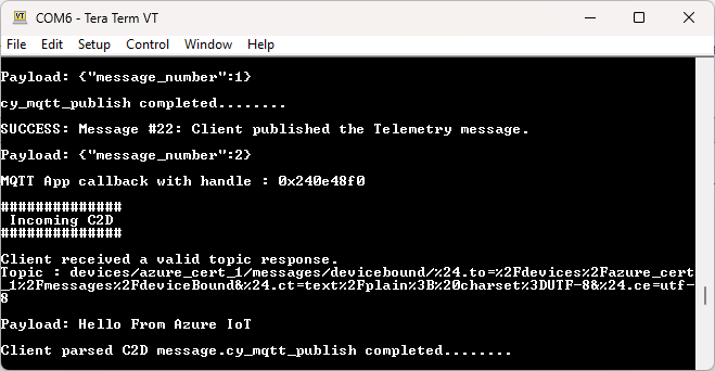
See
Figure 61
to see a message from the cloud printed in the terminal.
Figure 61.
C2D message
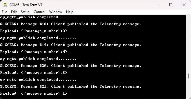
Telemetry :
The
Azure Device App
sends 100 telemetry messages to the Azure IoT Hub. If the network disconnects, the application will exit. The device metrics can be checked on the Azure Hub for analysis of Telemetry,
.
Figure 62.
Telemetry message
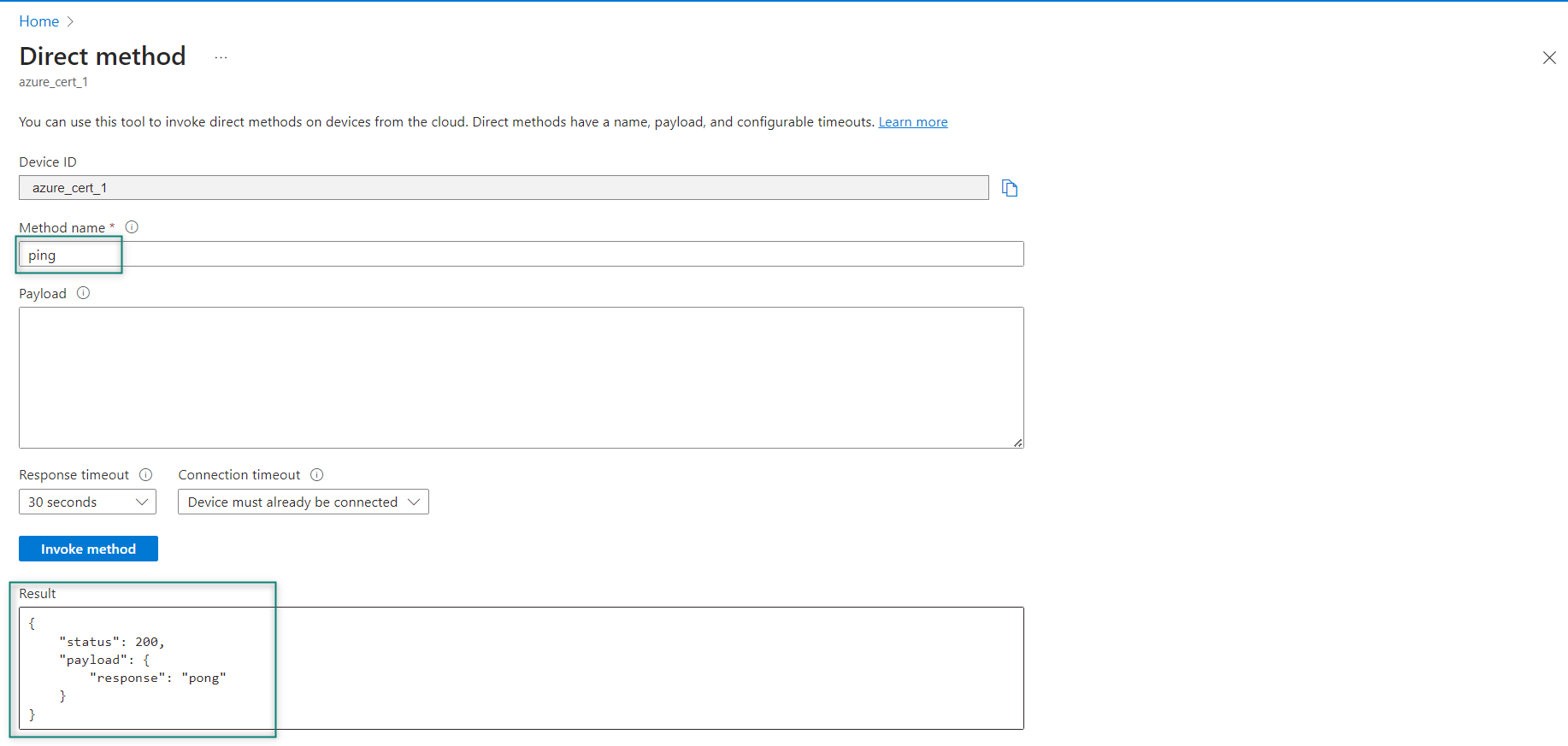
Methods :
The
Azure Device App
receives incoming method commands invoked from the Azure IoT Hub to the device. It receives all method commands sent from the service. If the network disconnects while waiting for a message, the application will exit.
To send a method command, select your device's
Direct Method
tab in the IoT Hub of the Azure portal. Enter a method-named
ping
in the
Method Name
field and click the
Invoke method
, which if successful will return the following JSON payload visible in the
Result
section of the
Direct method
tab in the Azure portal.
("response": "pong")
Figure 63.
Direct method
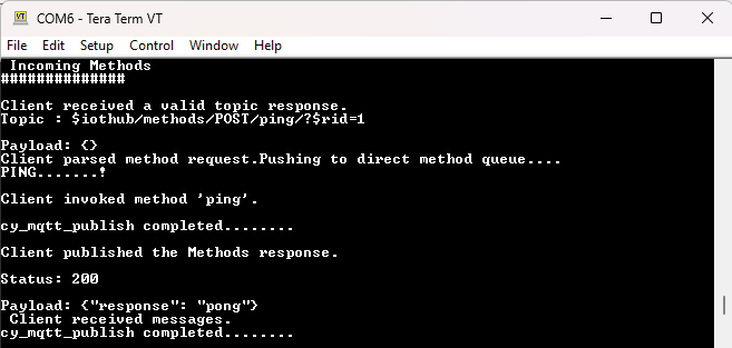
No other method commands are supported. If any other methods are attempted to be invoked, the log will report that the method is not found.
Figure 64.
Incoming Methods
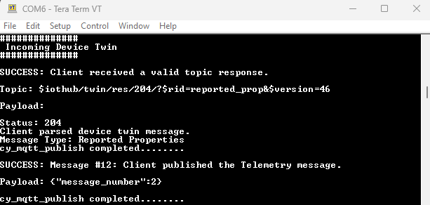
Device twin :
The
Azure Device App
uses the Azure IoT Hub to get the device twin document, send a reported property message, and receive up to five desired property messages. When the desired property message is received, the application will update the twin property locally and send a reported property message back to the service. If the network disconnects while waiting for a message from the Azure IoT Hub, the application will exit.
A property named
Test_count
is supported for this application. To send a device twin desired property message, select the device's
Device twin
tab in the IoT Hub of the Azure portal. Add the
Test_count
property along with the corresponding value to the
desired
section of the JSON, an example is shown below. Click
Save
to update the twin document and send the twin message from the cloud to the device.
"properties": (
     "desired": (
         "Test_count": 141,
         "$metadata": (
             "$lastUpdated": "2024-05-23T11:19:40.5236057Z"
         ),
         "$version": 1
     ),
Figure 65.
Incoming Device Twin
PnP <Plug and Play>
The application connects an IoT Plug and Play enabled device with the
Digital Twin Model ID
(DTMI). The application waits for a message and will exit if the network disconnects.
To interact with the application, use the Azure IoT Explorer or use the Azure portal directly. The capabilities are Device twin, Direct method (Command), and Telemetry.
Device Twin :
Two device twin properties are supported in this application:
The desired property is named
targetTemperature
with a
double
value for the desired temperature
A reported property named
maxTempSinceLastReboot
with a
double
value for the highest temperature reached since device boot.
To send a device twin desired property message, select your device's
Device Twin
tab in the Azure portal. Add the
targetTemperature
property along with a corresponding value to the desired section of the JSON object, as shown below. Select
Save
to update the twin document and send the twin message to the device.
Save to update the twin document and send the twin message to the device.
"properties": (
   "desired": (
         "targetTemperature": 68.5,
         "$metadata": (
            "$lastUpdated": "2024-05-23T11:25:53.7315952Z"
         ),
         "$version": 1
   ),
When the desired property message is received, the application will update the twin property locally and send a reported property of the same name back to the service. This message will include a set of "ack" values:
ac
for the HTTP-like ack code,
av
for the ack version of the property, and an optional
ad
for an ack description.
Upon selecting the
Refresh
button on the
Device Twin
portal, the updated properties can be seen in the reported section as shown below:
(
   "properties":
   (
      "reported":
      (
         "targetTemperature":
         (
            "value": 68.5,
            "ac": 200,
            "av": 14,
            "ad": "success"
         ),
         "maxTempSinceLastReboot": 74.3,
         ...
      )
   )
)
Direct method :
One device command is supported in this application:
getMaxMinReport
.
If any other commands are attempted to be invoked, the log will report that the command is not found. To invoke a command, select your device's
Direct Method
tab in the Azure portal. Enter the command name
getMaxMinReport
in the
Method Name
field along with a payload using an ISO 8061 time format and select
Invoke method
. A sample payload is as follows:
"2023-08-18T17:09:29-0700"
The command will send back to the service a response containing the following JSON payload with the updated values in each field. It is visible in the
Result
section of the
Direct Method
tab in the Azure portal. An example response is shown below:
Note:
The system time at the time of sending the response is reflected in endTime.
("status":400,"payload":("maxTemp":68.5,"minTemp":22,"avgTemp":45.25,"startTime":"2020-08-18T17:09:29-0700","endTime":"1970-01-01T00:00:31+0000"))
Telemetry :
The device sends the value of current temperature in JSON format with the field name
temperature
as telemetry data using the Twin and Direct methods.
Summary
The application note introduced the cloud connectivity services offered by Infineon Technologies. It also explained the module partners and cloud connectivity solutions provided by ModusToolbox™. It has explained the step-by-step demonstration on how to build a AWS_MQTT and Azure_IoT code examples to test it on the PSOC™ Edge E84 MCU.
References
Contact
Infineon Support
to obtain these documents.
Application notes:
AN235935 - Getting started with PSOC™ Edge E8 MCU on ModusToolbox™ software
AN236697 - Getting started with PSOC™ MCU and AIROC™ connectivity devices
AN228571 - Getting started with PSoC™ 6 MCU on ModusToolbox™ software
Webpages:
PSoC™ 6 MCU
ModusToolbox™ software
ModusToolbox™ for connectivity
ModusToolbox™ GitHub page
Infineon's Make IoT work
AWS IoT Developer Guide
Getting started with AWS IoT Core
Azure IoT
Code examples:
Glossary
There are a few terminologies related to cloud services. This document uses the following list of terms.
Term | Description |
|---|---|
Internet of Things | The Internet of Things (IoT) is a network of physical devices embedded with sensors, software, and other technologies that allows them to connect and exchange data with other devices and systems over the internet. |
Web services | Web services are software components that interact over networks using standardized protocols like HTTP and XML. They function as intermediaries, enabling communication and data exchange between different applications and systems. |
Amazon Web Services (AWS) | A cloud computing platform offered by Microsoft, providing a comprehensive set of services for building, deploying, and managing applications. |
Microsoft Azure | A cloud computing platform offered by Amazon, providing a wide range of services for businesses of all sizes, from startups to large enterprises. |
Topics | It defines the category of a message and allow subscribers to access data through topics. |
MQTT Publisher | Devices or any application that send data to the broker. |
MQTT Subscriber | Devices or any application that are interested to access specific topics. |
MQTT Broker | The central server responsible for message routing between publishers and subscribers. |
Revision history
Document revision | Date | Description of changes |
|---|---|---|
*A | 2025-09-04 | Release to web |
Trademarks
The Bluetooth® word mark and logos are registered trademarks owned by Bluetooth SIG, Inc., and any use of such marks by Infineon is under license.
PSOC™, formerly known as PSoC™, is a trademark of Infineon Technologies. Any references to PSoC™ in this document or others shall be deemed to refer to PSOC™.