AN238041 PSOC™ Edge provisioning specification
About this document
Scope and purpose
This application note provides essential information for enabling the provisioning process for the
PSOC™ Edge
series of devices. It details the
certificates,
Secure Enclave (SE)
RAM application, Edge Protect Tools, and policy information.
Intended audience
This document is intended for users with advanced knowledge of the various components involved in the
PSOC™ Edge
provisioning process.
This document presumes that you are already familiar with
AN237849 – Getting started with PSOC™ Edge security
Introduction
Provisioning is the process of injecting authorized keys
, certificates,
and/or policy configuration into a device. Original equipment manufacturers (OEMs) use the provisioning process to load OEM Root-of-Trust (RoT) keys
, OEM certificates,
and OEM policies into the
PSOC™ Edge
device. The provisioning of OEM keys, certificates, and policies transfers device ownership from Infineon to the OEM.
It can also be used to replace the extended boot image on the device or transition to the production lifecycle.
PSOC™ Edge
devices can be provisioned using Infineon's Edge Protect Tools package, which creates and downloads a signed provisioning packet into the device. This provisioning packet includes
an SE RAM
application capable of performing the provisioning, along with input parameters for the
SE
RAM application, such as the policy file
, keys, certificates, and the extended boot image (optional)
.
This document provides detailed information about the various types of certificates, policies,
SE
RAM application, and downloadable module (DLM) packages, all of which are included in or generated by Edge Protect Tools.
Provisioning overview
The provisioning process enables the OEM to configure several boot and debug related policy configurations. As a primary step, the OEM is required to ‘own’ the device before making any changes to the Infineon default policies on the device. To take ownership of the device, the OEM needs to generate its own keys and certificate, and provision the device with these, as shown in
Step 1
of
Figure 1
. This step can be performed whenever the OEM needs to change the root of trust (RoT) keys on the device, even while the device is in the development lifecycle stage (LCS). After the transfer of ownership is completed, the OEM must then use the OEM_ROT_KEY to perform further provisioning of the device for the purpose of policy modification as shown in
Step 2
of
Figure 1
. There are no restrictions on the number of times the device can be provisioned in the development lifecycle stage. Therefore, provisioning can be utilized to carry out the following operations on the device:
Replace keys and certificates
Replace the OEM policy file
Replace the extended boot
The device can then be provisioned 'one' time to transition into the production lifecycle by using the production certificate. After the device is moved into the production lifecycle stage, it cannot be returned to the development LCS and the OEM_ROT_KEY can no longer be changed through provisioning.
Note:
For PSA L4 compliance, cryptographic keys and certificates outside of the product, used for example for product personalization, shall be handled by the OEM in a secure way. Actors in charge of product management, for instance product personalization, shall be trusted personnel.
Figure 1.
Provisioning overview
See Section "Getting started" in
AN237849 – Getting started with PSOC™ Edge security
for detailed steps on initiating the provisioning process.
Re-provisioning
While in the production lifecycle stage (LCS), the device can only be re-provisioned if the re-provisioning policy for the specific policy field has been configured accordingly. For more details, see
Re-provisioning policy
.
Certificates
A digital certificate or a public-key certificate can be used by any entity to establish the ownership of a public key. Certificates contain a public key, information about the public key, identity of its owner, and the signature of the certificate authority (CA) that verifies the content of the certificate. A certificate signing request (CSR) is a request sent from the entity that owns the public key to the certificate authority to verify the information provided in the CSR and generate the certificate. There are different kinds of certificates and CSR that are used in the context of PSOC™ Edge devices.
Certificate | Purpose |
|---|---|
OEM certificate | This contains the OEM_ROT_PUBLIC_KEY, which is signed by the Infineon CA and provisioned by the OEM to transfer the ownership of the device. See OEM certificate |
OEM CSR | This is a self-signed certificate signing request sent from the OEM to the Infineon CA to generate the OEM certificate. See OEM CSR |
Device certificate | This contains the DICE_DeviceID public key and certifies that the device is a genuine Infineon device. The certificate is signed by the Infineon manufacturing CA and is provisioned during the Infineon device manufacturing process. See Device certificate |
Alias certificate | This contains the Alias public key and is signed by the DICE_DeviceID private key. This certificate is generated on the device and updated every time the device is re-provisioned on the field. This can be used for device attestation purposes. See Alias certificate |
Infineon manufacturing certificate | This certificate contains the Infineon manufacturing public key, and is self-signed with the Infineon manufacturing private key. This certificate is also stored in the device during the manufacturing process and can be retrieved by the user. See Infineon manufacturing certificate |
For PSOC™ Edge devices, the certificates use the CBOR/COSE format. See the
Appendix
section for more details.
The device ownership is transferred to the OEM when the device is provisioned with the OEM Certificate. This certificate is signed by Infineon through Edge Protect Signing Service and is verified by the device after provisioning. This process ensures that only Infineon approved OEM certificate can be provisioned on the device. OEM certificate contains the OEM root of trust public Key. The OEM root of trust private key must be protected by the OEM and used during provisioning of the device to sign the OEM policy, and also to sign the user application images before programming, in case secure boot is enabled.
For device attestation purposes, the alias certificate can be used. Alias certificate can be verified with the DICE_DeviceID public key, which can be extracted from the device certificate. Device certificate can be verified with the manufacturing public key, which is extracted from the manufacturing certificate. These certificates are stored in the protected nonvolatile memory (NVM) region. See
Certificate verification
for certificate verification steps.
Note:
Alias key pair and DICE_DeviceID key pair are only accessible through the Secure Enclave runtime services (SE RT) available on an edge protect category (EPC) 4 part. On an EPC 2 part, a copy of the alias key pair generated during manufacturing is stored in the NVM as IAK_LITE_KEY.
Figure 2.
Certificate chain of trust (CoT)
OEM certificate
The OEM certificate contains the OEM_ROT_PUBLIC_KEY and enables the OEM to take ownership of the device. This certificate must be signed by the IFX_ROT_KEY, and generated by
Infineon's Edge Protect Signing Service
(EPSS) based on the CSR uploaded by the OEM. For more detailed instructions on generating the OEM CSR and OEM certificate, see
AN237849 – Getting started with PSOC™ Edge security
.
The OEM certificate can be of two types:
Development certificate:
The development OEM certificate contains the OEM_ROT_PUBLIC_KEY that is used by the OEM during the development LCS of the device. In the development lifecycle, the device can be provisioned multiple times to change the policy and/or keys, and can also be restored to Infineon default policy settings. When the development certificate is used, the keys are stored in a mutable memory and the lifecycle of the device remains unchanged. Development OEM keys do not need to be secured and can be replaced at any time by the OEM
Production certificate:
The production OEM certificate is used to transition the device from the development to production LCS. This certificate must contain the production OEM_ROT_PUBLIC_KEY that will be stored in the immutable memory region. Two sets of the OEM_ROT_KEYs are supported to enable key revocation in the event of a security breach. The production OEM ROT keys, used for production devices, must be securely stored and used by the OEM. These keys cannot be replaced by provisioning
Item | Field | Example value | Data type | Description |
|---|---|---|---|---|
1 | VERSION | 1 | String | Certificate version |
2 | TEMPLATE_TYPE | OEM_CERT | String | Certificate template |
3 | CERTIFICATE_NAME | OEM_CSR | String | Certificate name |
4 | TYPE | DEVELOPMENT | String | Certificate type. Applicable values: DEVELOPMENT, PRODUCTION |
5 | ISSUER | Dummy Corp. | String | Certificate issuer |
6 | ID | ABCDEF | HEX | Certificate (unique) ID |
7 | DATE | 2023-09-19 15:24:47 | String | The date of creation of the certificate |
8 | ALGORITHM | ES256 | String | Key algorithm. Applicable values: ES256, ES384 |
9 | SIGNER_ID | Dummy_OEM | String | Certificate signer ID |
10 | PUBLIC_KEY_0 | 049A0BFAC2727E7... | HEX | OEM_ROT public key 0 |
11 | PUBLIC_KEY_1 | 049A0BFAC2727E7... | HEX | OEM_ROT public key 1 |
12 | OEM | Dummy_OEM | String | OEM name |
12 | PROJECT | Dummy_Project | String | Project name |
13 | PROJECT_NUMBER | 123 | String | Project number |
The OEM certificate generated by Infineon's EPSS will be in the COSE format. A JSON representation of the same is shown in the following code block:
OEM certificate in JSON format
(
  "VERSION": "1",
  "TEMPLATE_TYPE": "OEM_CERT",
  "CERTIFICATE_NAME": "OEM_CSR",
  "TYPE": "DEVELOPMENT",
  "ISSUER": "Dummy Corp.",
  "ID":h'ABCDEF',
  "DATE":"2023-09-19 15:24:47",
  "ALGORITHM": "ES256",
  "SIGNER_ID": "555",
  "PUBLIC_KEY_0": h'04C55A85F02FDF5D2256397C7C154DAF2AECDBB56403F4ED279D47AACE1D9270063BFB09AB8CFFE8DC2172DC354D377495ECFE2FE0C8A55E3B8F521F79FF874CBB',
  "PUBLIC_KEY_1": h'04504D54E877726B856CF59940CCE458DA85F805FE1AC4CDEF692B598B3CE11E772C841F2F6C09998090E5D85C468BBE85431FE4EFBA6AED8D9777E2E46A92C84D',
  "OEM": "Dummy_OEM",
  "PROJECT": "Dummy_Project",
  "PROJECT_NUMBER": "123"
)
OEM CSR
The OEM certificate signing request (CSR) must be generated by the OEM with the OEM_ROT_PUBLIC_KEY and other relevant information. The CSR is signed by the OEM_ROT_PRIVATE_KEY. OEM CSR can be generated using the Edge Protect Tools. The OEM CSR must be submitted to
Infineon's Edge Protect Signing Service
(EPSS) to generate the OEM certificate.
Item | Field | Example value | Data type | Description |
|---|---|---|---|---|
1 | VERSION | 1 | String | Certificate version |
2 | TEMPLATE_TYPE | OEM_CSR | String | Certificate type |
3 | CERTIFICATE_NAME | – | – | Not applicable |
4 | OEM | Dummy_OEM | String | OEM name |
5 | PROJECT | Dummy_Project | String | Project name |
6 | PROJECT_NUMBER | 123 | String | Project number |
7 | ISSUER | Dummy Corp. | String | Certificate issuer |
8 | SIGNER_ID | 555 | String | Signer ID |
9 | ALGORITHM | ES256 | String | Key algorithm. Applicable values: ES256, ES384 |
10 | PUBLIC_KEY_0 | "keys/oem_public_key_0.pem" | String | Path to the ECDSA P-256 public key or a 65-byte hex string |
11 | PUBLIC_KEY_1 | "keys/oem_public_key_1.pem" | String | Path to the ECDSA P-256 public key or a 65-byte hex string |
12 | TYPE | DEVELOPMENT | String | Certificate type. Applicable values: DEVELOPMENT, PRODUCTION |
13 | DATE | 2023-09-19 15:24:47 | String | The date of creation of the certificate in the format: YYYY-MM-DD hh:mm:ss. If not provided, the system time will be used |
14 | ID | ABCDEF | HEX | Certificate (unique) ID |
The OEM CSR generated by the Edge Protect Tools will be in the CBOR Object Signing and Encryption (COSE) format. A JSON representation of the same is shown in the following code block:
OEM CSR in JSON format
(
  "VERSION": "1",
  "TEMPLATE_TYPE": "OEM_CSR",
  "CERTIFICATE_NAME": "",
  "OEM": "Dummy_OEM",
  "PROJECT": "Dummy_Project",
  "PROJECT_NUMBER": "123",
  "ISSUER": "Dummy Corp.",
  "SIGNER_ID": "555",
  "ALGORITHM": "ES256",
  "PUBLIC_KEY_0": "keys/oem_public_key_0.pem",
  "PUBLIC_KEY_1": "keys/oem_public_key_1.pem",
  "TYPE": "DEVELOPMENT",
  "DATE": "2023-09-19 15:24:47",
  "ID": h'ABCDEF'
  )
Device certificate
Devices must authenticate themselves to services, establish secure communications, and attest to their security configuration. DICE_DeviceID is computed during device provisioning at the Infineon factory and the DICE_DeviceID public key is certified by Infineon's manufacturing CA to form the Infineon device certificate. The private section of the DICE_DeviceID is never exposed outside of the Secure Enclave to user code (both secure and non-secure), but it can be used for crypto operations on the EPC 4 parts via the Secure Enclave runtime (SE RT) services library.
The Infineon device certificate can be used to check the authenticity of the device and for attestation purposes (for EPC 4 devices). This certificate contains the DICE_DeviceID public key and device-specific information. You can extract the DICE_DeviceID public key from this certificate and use it to verify any device information that is signed by the DICE_DeviceID private key. For example, the alias certificate is signed by the DICE_DeviceID private key and this certificate can be verified by using the DICE_DeviceID public key.
The device certificate is signed by Infineon manufacturing private key and stored into the protected NVM region during the device manufacturing.
The device certificate can be read from the device. See the
device architecture reference manual
for more information. It is also returned as part of the device integrity exam response. See the
Appendix
section for details on the device integrity exam.
Item | Field | Example value | Data type | Description |
|---|---|---|---|---|
1 | VERSION | 1 | String | Certificate version |
2 | TEMPLATE_TYPE | DEVICE_CERT | String | Certificate type |
3 | CERTIFICATE_NAME | – | – | Certificate name |
4 | TYPE | – | – | Not applicable |
5 | ISSUER | IFX | String | Certificate issuer |
6 | ID | ABCDEF | HEX | Certificate (unique) ID |
7 | DATE | 2023-09-19 15:24:47 | String | The date of creation of the certificate |
8 | ALGORITHM | ES256 | String | Key algorithm. Applicable values: ES256, ES384 |
9 | SIGNER_ID | 555 | String | Certificate signer ID |
10 | PUBLIC_KEY_0 | 049A0BFAC2727E7... | HEX | DICE_DeviceID public key |
11 | DIE_ID | 00000000000000000000 | HEX | DIE_ID identifies LOT (3-byte) + WAFER (1-byte) + XY (2-byte) + SORT (1-byte) + DATE (3-byte) of DIE = (10-byte) |
12 | FAMILY_ID | 0x1501 | HEX | Device family ID |
13 | REVISION_ID | 0x21 | HEX | Device revision ID |
14 | ROM_BOOT_VERSION | 1.0.0.6775 | String | Version of ROM_BOOT on the device |
15 | RRAM_BOOT_VERSION | 1.0.0.6775 | String | Version of the RRAM_BOOT on the device |
The device certificate will be in the COSE format. A JSON representation of the same is shown in the following code block:
Device certificate in JSON format
(
"VERSION": "1",
"TEMPLATE_TYPE": "DEVICE_CERT",
"CERTIFICATE_NAME": "",
"TYPE": "",
"ISSUER": "Acme Corp.",
"ID": h'ABCDEF',
"DATE": "2023-09-19 15:24:47",
"ALGORITHM": "ES256",
"SIGNER_ID": "555",
"PUBLIC_KEY_0": h'044E2828176CA3D61D34F23C433003222C3BA8B53A1C28AB2CA96A91964C7AC4D7E514E7FA2754A5E7E694FC2BB912EA704210D501B3556E7FFF1869C4B404F4FC',
"DIE_ID": h'00000000000000000000',
"FAMILY_ID": h'1501',
"REVISION_ID": h'21',
"ROM_BOOT_VERSION": "2.0.0.6775",
"RRAM_BOOT_VERSION": "2.0.0.6775"
)
Alias certificate
The alias certificate is utilized to certify the alias public key as the root credential for the device. This certificate is signed by the DICE_DeviceID private key. As a result, the alias certificate forms a chain back to the device certificate and ultimately to the Infineon manufacturing CA.
Alias keys can be used to sign attestation messages with ALIAS_PRIVATE_KEY as the device's root key. The alias and device certificates can be shared along with the signed messages. The recipient of the attestation message can validate the message signature by extracting the ALIAS_PUBLIC_KEY from the alias certificate.
The alias certificate can be verified using the DICE_DeviceID public key that is extracted from the device certificate.
In the development LCS, the alias key pair is generated once at the Infineon factory during manufacturing. It is not regenerated again in the development LCS. When the device transitions to the production LCS, the alias key pair is regenerated. It is also regenerated in the production LCS, if there is any device update.
The alias certificate is stored in the protected NVM region and can be retrieved. See the
device architecture reference manual
for more information.
The alias certificate is also returned as part of the device integrity exam response. See the
Appendix
section for details on the device integrity exam.
Note:
For EPC 2 devices, the alias key pair within the Secure Enclave is not accessible. During Infineon factory manufacturing, a copy of the alias key pair is stored in the MAIN NVM region, referred as IAK_LITE keys. IAK LITE keys can be used for initial attestation purposes. See the
device architecture reference manual
.
Item | Field | Example value | Data type | Description |
|---|---|---|---|---|
1 | VERSION | 1 | String | Certificate version |
2 | TEMPLATE_TYPE | ALIAS_CERT | String | Certificate type |
3 | CERTIFICATE_NAME | 00000000000000000000_ALIAS | String | Certificate name |
4 | TYPE | Not Applicable | ||
5 | ISSUER | 00000000000000000000_ALIAS | String | Not Applicable |
6 | ID | 00000000000000000000 | HEX | Certificate (unique) ID |
7 | DATE | String | The date of creation of the certificate | |
8 | ALGORITHM | ES256 | String | Key algorithm. Applicable values: ES256, ES384 |
9 | SIGNER_ID | 00000000000000000000 | String | Not Applicable |
10 | PUBLIC_KEY_0 | 048EEF4826086A... | HEX | ALIAS public key |
11 | BASE_SE_RTS_VERSION | 1.0.0.2114 | String | Version of Basic RT services on the device |
12 | SE_RTS_VERSION | 1.0.0.2114 | String | Version of SE RT services on the device |
12 | EXTENDED_BOOT_VERSION | 1.1.0.1656 | String | Version of Extended boot on the device |
13 | SILICON_ID | 0xabcd | HEX | Silicon ID |
The alias certificate will be in the COSE format. A JSON representation of the same is shown in the following code block:
Alias certificate in JSON format
(
"VERSION": "1",
"TEMPLATE_TYPE": "ALIAS_CERT",
"CERTIFICATE_NAME": "00000000000000000000_ALIAS",
"ISSUER": "00000000000000000000_ALIAS",
"ID": h'00000000000000000000',
"DATE": "",
"ALGORITHM": "ES256",
"SIGNER_ID": "00000000000000000000",
"PUBLIC_KEY_0": h'0492F2248FB942F42936CD873D1F045C3164CB95D7A485EC056FC026634A1A0C3F7BFCBE213E812BB40ED4C789AD2F8ACC5705C47A849F951CF7DE9F51D2F0D791',
"BASE_SE_RTS_VERSION": "1.0.0.2114",
"SE_RTS_VERSION": "1.0.0.2114",
"EXTENDED_BOOT_VERSION": "1.1.0.1656",
"SILICON_ID": h'81ED'
)
Infineon manufacturing certificate
Infineon manufacturing key is used to sign the device certificate during the manufacturing of a device at the Infineon factory. The manufacturing certificate contains the public key that can be used to verify the device certificate and the manufacturing certificate itself. The Infineon manufacturing certificate acts like a CA and certifies the chain of trust up to the alias certificate.
Item | Field | Example value | Data type | Description |
|---|---|---|---|---|
1 | VERSION | 1 | String | Certificate version |
2 | TEMPLATE_TYPE | MANUFACTURING_CERT | String | Certificate template type |
3 | CERTIFICATE_NAME | – | String | Certificate name |
4 | TYPE | – | Certificate type | |
5 | ISSUER | IFX | String | Certificate issuer |
6 | ID | ABCDEF | HEX | Certificate (unique) ID |
7 | DATE | 2024-12-17 09:42:40 | String | The date of creation of the certificate |
8 | ALGORITHM | ES256 | String | Key algorithm. Applicable values: ES256, ES384 |
9 | SIGNER_ID | 555 | String | OEM ID |
10 | PUBLIC_KEY_0 | 048EEF4826086A... | HEX | Manufacturing public key |
11 | MFG | IFX | String | Manufacturer name |
The device certificate will be in the COSE format. A JSON representation of the same is shown in the following code block:
Device certificate in JSON format
(
"VERSION": "1",
"TEMPLATE_TYPE": "MANUFACTURING_CERT",
"CERTIFICATE_NAME": "",
"TYPE": "",
"ISSUER": "IFX",
"ID": h'ABCDEF',
"DATE": "2024-12-17 09:42:40",
"ALGORITHM": "ES256",
"SIGNER_ID": "555",
"PUBLIC_KEY_0": h'045FAC10294FDB0BDBB90F6C8960AAC940212074E02FEA96CC84C36CA288BA90D8F9F315A68FD115B708CE177AEC9E1AB4D4F7D2A49C92EDA9B3CEC2D466497FA5',
"MFG": "IFX"
)
Certificate verification
Follow these steps to verify the device certificate:
Retrieve the certificates by running an integrity-exam
edgeprotecttools -t pse8xs2 integrity-exam --device-cert dev_cert.cbor --alias-cert alias_cert.cbor --chain-of-trust manufacturing_cert.cbor
Note:
Alternatively you can read the certificate from the device memory and convert it to *
.cbor
format. See the
device architecture reference manual
for the memory address
Use target '-t pse8xs4' for EPC4 device
Extract the manufacturing pub key from the manufacturing certificate
edgeprotecttools cbor2json -i manufacturing_cert_0.cbor | grep -i "PUBLIC_KEY_0" | awk -F":" '(print $2)' | tr -d "' h ," > manufacturing_pub_key.txt
Copy key data from
manufacturing_pub_key.txt
to
./keys/ec_key_tmpl.json
(
"description": "This is a template for creating a JWK file containing EC public key based on a key public numbers (CURVE=secp256r1)",
"pub": "04A9C071DFFBB18CF8CC23C33A071908B3A1717E0D97D37EC4F6496A5D5E8DB7063E0FB0F5EAA6420F3F6CD2AB2FC5648394D20D9883DFA93E20E447A7D7693A2C"
)
Convert key to PEM format
edgeprotecttools --no-interactive-mode create-key --key-type ECDSA-P384 --template keys/ec_key_tmpl.json --format PEM -o manufacturing_pub_key.pem
Verify manufacturing certificate using the manufacturing public key
edgeprotecttools cose-verify -i manufacturing_cert_0.cbor --key manufacturing_pub_key.pem
Verify the device certificate using the manufacturing public key
edgeprotecttools cose-verify -i dev_cert.cbor --key manufacturing_pub_key.pem
Extract the device public key from the device certificate
edgeprotecttools cbor2json -i dev_cert.cbor | grep -i "PUBLIC_KEY_0" | awk -F":" '(print $2)' | tr -d "' h ," > device_pub_key.txt
Copy key data from
device_pub_key.txt
to
./keys/ec_key_tmpl.json
(
"description": "This is a template for creating a JWK file containing EC public key based on a key public numbers (CURVE=secp256r1)",
"pub": "04A9C071DFFBB18CF8CC23C33A071908B3A1717E0D97D37EC4F6496A5D5E8DB7063E0FB0F5EAA6420F3F6CD2AB2FC5648394D20D9883DFA93E20E447A7D7693A2C"
)
Convert key to PEM format
edgeprotecttools --no-interactive-mode create-key --key-type ECDSA-P256 --template keys/ec_key_tmpl.json --format PEM -o device_pub_key.pem
Verify an alias certificate using the device public key
edgeprotecttools cose-verify -i alias_cert.cbor --key device_pub_key.pem
Decoding COSE certificates
Certificates will be stored in the COSE format and you can decode the certificate by making use of CBOR/COSE decoders.
Follow these steps to read the device certificate using ModusToolbox™ and decode using
CBOR
playground.
Export to text file from the ModusToolbox™ memory window. See the
architecture reference manual
for memory address and sizes of the certificates
2D010000D28444A1013822A058C1A67819444943455F4445564943455F49445F
5055424C49435F4B4559584104D299902AC1394F6F50A5A74039C7FA3248D81B
A9BE73354F5414057493D503D6D6D8CF792DC62A4AB73B7B6B149B4AB015C1CD
357C242AB3CE3D516714256D45664449455F49444A8EA6FCAA0203010C0A1770
524F4D5F424F4F545F56455253494F4E48010000007F0F0000715252414D5F42
4F4F545F56455253494F4E4801000000C11100006946414D494C595F49444232
126B5245564953494F4E5F494441565860B1230F15FA97F7679653A357BCC0AA
052013AA970846A155610BDAB6A07BCDE6B00BB8ACE13024400B38DAF79625BF
3D1C35BA3BD1988F545559A341298D5F4CF482C74288F61113AADABA94B0DD2C
6018A6D9637722AF712FC29B18883B22602B1E81D70000000000000000000000
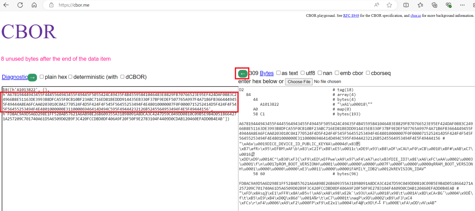
Copy paste the COSE data without 4-byte length to the right side of the page at
CBOR
and press the left arrow button as shown in
Figure 3
. The COSE certificate will be decoded into the CBOR data and signature
Figure 3.
Decoding COSE certificate
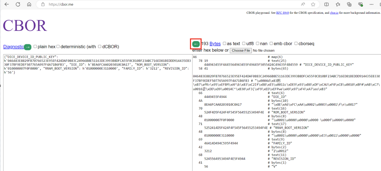
Copy the CBOR part, highlighted on the left-hand side shown in
Figure 3
, and paste again to the right side of the page at
CBOR
and press the left arrow button. See the decoded certificate fields on the left-hand side of the CBOR page
Figure 4.
Decoding CBOR data
Policy
The
PSOC™ Edge
device's boot configuration is dictated by a policy file. All policy configurations are applied during device boot up by the Infineon
boot firmware (RRAM boot + Extended boot)
. In the Infineon factory, the device is provisioned with a set of default policy configurations. This default policy is packaged as a part of the Edge Protect Tools package and contains different sections that can be broadly classified into the three OEM policy sections:
Debug policy
Re-provisioning policy
Extended boot policy
The policy file also includes a section where the extended boot image location (on the host PC) can be specified in case the extended boot image requires an update. Additionally, there are sections where the OEM can input user certificates, user keys, and OEM_ROT_KEY revocation requests.
Figure 5.
OEM policy file
Once the Edge Protect Tools package is initialized on the host PC, see the JSON policy in the
<application-directory>/policy/policy_oem_provisioning.json
file. This file can be edited using any text editor to customize the policy.
The JSON policy file that contains the provisioning data or reference to it, is converted into a CBOR packet that contains all provisioning data by Edge Protect Tools. This packet is then signed accordingly to the COSE format and the final packet is sent to the device during provisioning by Edge Protect Tools. The
SE
RAM application on the device then receives the packet, verifies the packet's signature, and process the CBOR payload to get data for the provisioning. Typically, the
SE
RAM application processes provisioning data to convert it to the asset format stored on the device.
Debug policy
The debug policy configuration is used by the OEM to enable or disable debug ports. Infineon's default policy configuration enables and opens up all the debug configurations.
In the development LCS, the system access port (SYS-AP) always remains open (even if configured as disabled by the policy file). This is to ensure that the device can always be recovered through the SYS-AP and will not be bricked during development. All other debug ports can be closed during the development phase to closely emulate the production device.
For a production device, it is recommended to close all debug ports for optimum device security.
Note:
CM55 debug is not controlled by the policy configuration. It should be controlled by the secured CM33 user application.
The default policy configurations are shown in the following code block:
Debug default policy configuration
"debug": (
"cm33": (
"cpu": (
"description": "CPU access port debug restriction",
"applicable_conf": "Disabled, Enabled, Allowed",
"value": "Enabled"
),
"allowed": (
"description": "Indicates who is allowed to access the AP. The option is applicable when CPU control is 'Allowed'",
"applicable_conf": "Firmware, Certificate, Open",
"value": "Open"
),
"dbgen": (
"description": "Invasive Debug. It implies non-invasive is also enabled",
"value": true
),
"niden": (
"description": "Non-Invasive Debug (monitoring without control)",
"value": true
),
"spiden": (
"description": "Secure Privileged Invasive Debug. The control field is not applicable in NORMAL_NO_SECURE LCS",
"value": true
),
"spniden": (
"description": "Secure Privileged Non-Invasive Debug. The control field is not applicable in NORMAL_NO_SECURE LCS",
"value": true
),
"secure": (
"description": "Secure Privileged Debug. The control field is not applicable in NORMAL_NO_SECURE LCS",
"value": true
)
),
"system": (
"ap": (
"description": "System access port (SYS-AP) restriction",
"applicable_conf": "Disabled, Enabled, Allowed",
"value": "Enabled"
),
"allowed": (
"description": "Indicates who is allowed to access the AP. The option is applicable when AP control is 'Allowed'",
"applicable_conf": "Firmware, Certificate, Open",
"value": "Open"
),
"mpc_ppc_enable": (
"description": "Indicates that the MPC/PPC on the system access port must be programmed and locked according to the settings in the next 4 fields.",
"value": true
),
"rram_otp_enable": (
"description": "This field indicates if access is allowed to general purpose OTP",
"applicable_conf": "Entire region, Nothing",
"value": "Entire region"
),
"rram_nvm_enable": (
"description": "This field indicates what portion of RRAM MAIN_NVM (including reclaimed area of PROTECTED_NVM but excluding MAIN_NVM Region 0 and Region 1)",
"applicable_conf": "Entire region, 7/8th, 3/4th, 1/2, 1/4th, 1/8th, 1/16th, Nothing",
"value": "Entire region"
),
"ram_enable": (
"description": "This field indicates what portion of SRAM is accessible through the system access port. Only a portion of SRAM starting at the bottom of the area is exposed, like the 'rram_nvm' option",
"applicable_conf": "Entire region, 7/8th, 3/4th, 1/2, 1/4th, 1/8th, 1/16th, Nothing",
"value": "Entire region"
),
"mmio_enable": (
"description": "This field indicates what portion of the MMIO region is accessible through the system access port",
"applicable_conf": "All MMIO registers, Only IPC MMIO, RAM app only, No MMIO access",
"value": "All MMIO registers"
)
),
"rma": (
"permission": (
"description": "Permission for transition to RMA LCS",
"value": true
)
),
"debug_key": (
"description": "ECDSA public key, used to verify debug token. Use the path to the ECDSA P-256 public key or a 65-byte hex string",
"value": ""
)
),
Re-provisioning policy
Once the PSOC™ Edge device transitions into the production LCS, only the policy fields set to 'true' in the re-provisioning policy are permitted to be changed through the re-provisioning process.
The default policy configurations are shown in the following code block:
Re-provisioning policy default configurations
"reprovisioning": (
  "description": "Reprovisioning policy. Used to restrict the assets reprovisioning",
  "debug": (
    "cm33": true,
    "system": true,
    "rma": true,
    "debug_key": true
  ),
  "extended_boot_policy": true,
  "user_keys": true,
  "user_certificate": true
),
For example, if the system access port is set to '
Enabled
' in the '
debug
' policy section and the '
debug
'- '
system
' field is set to '
true
' in the '
reprovisioning
' policy section during the transition to production LCS as shown in
1.Example policy configuration during 'transition to production LCS'
, after the device transitions into the production LCS, the system AP debug can be disabled by re-provisioning the device with a modified debug policy configuration as shown in
- Example policy configuration for re-provisioning
.
1.Example policy configuration during 'transition to production LCS'
"debug": {
    "system": {
      "ap": {
        "description": "System access port (SYS-AP) restriction. The SYS-AP restrictions are not enforced in the Development LCS",
        "applicable_conf": "Disabled, Enabled, Allowed",
        "value": "Enabled"
      },
      "allowed": {
        "description": "Indicates who is allowed to access the AP. The option is applicable when AP control is 'Allowed'",
        "applicable_conf": "Firmware, Certificate, Open",
        "value": "Open"
      },
..
},
..
"reprovisioning": {
  "description": "Reprovisioning policy. Used to restrict the assets reprovisioning",
  "debug": {
    "cm33": true,
    "system": true,
    "rma": true,
    "debug_key": true
  },
  "extended_boot_policy": true,
  "user_keys": true,
  "user_certificate": true
},
2.Example policy configuration for re-provisioning
"debug": {
    "system": {
      "ap": {
        "description": "System access port (SYS-AP) restriction. The SYS-AP restrictions are not enforced in the Development LCS",
        "applicable_conf": "Disabled, Enabled, Allowed",
        "value": "Disabled"
      },
      "allowed": {
        "description": "Indicates who is allowed to access the AP. The option is applicable when AP control is 'Allowed'",
        "applicable_conf": "Firmware, Certificate, Open",
        "value": "Open"
      },
..
},
Note:
Re-provisioning is not possible if the system access port (SYS-AP) has been disabled.
Device can be re-provisioned using the following Edge Protect Tools command after it has been transitioned to Production LCS
edgeprotecttools -t pse8xs2 reprovision-device -p policy/policy_oem_provisioning.json --key keys/oem_private_key_0.pem
Note:
The "reprovision-device" command should not contain
--ifx-oem-cert
option
Extended boot policy
The extended boot policy determines how the extended boot is configured. Some of the extended boot policy configurations include:
Enable/disable secure boot feature
Start address of the OEM application
Alternate start address of the OEM application
Enable/disable external flash configuration in extended boot
External flash configurations for booting from external flash
Infineon's default extended boot policy configurations include:
Disables secure boot
Configures the extended boot to boot from RRAM
Enables booting from an alternate location
Enables serial memory interface (SMIF) configuration in extended boot
Configures external quad SPI (QSPI) flash as the alternate boot source
The default policy configurations are shown in the following code block:
Extended boot policy default configurations
"extended_boot_policy": (
  "secure_boot": (
    "description": "Disable/Enable secure boot option",
    "value": false
  ),
  "clock": (
    "description": "Defines default core clock speed in MHz",
    "applicable_conf": "200, 100, 50, 5",
    "value": 200
  ),
  "listen_window": (
    "description": "Defines listen window timeout in ms",
    "value": 100
  ),
  "enable_alt_serial": (
    "description": "Disable/Enable Alternate serial interface",
    "value": true
  ),
  "cm33_ram_app": (
    "enable": (
      "description": "Disable/Enable CM33 OEM RAM applications",
      "value": true
    ),
    "address": (
      "description": "Start address of the CM33 OEM RAM application",
      "value": "0x34008000"
    )
  ),
    "oem_app_address": (
    "description": "Starting location of OEM application",
    "value": "0x3201100"
  ),
  "oem_alt_boot": (
    "description": "Disable/Enable alternate boot",
    "value": true
  ),
  "oem_alt_app_address": (
    "description": "Alternate starting location of OEM application",
    "value": "0x70100000"
  ),
  "external_flash": (
    "smif_exflash": (
      "description": "Disable/Enable search for SFDP compatible external flash device",
      "value": true
    ),
    "smif_chip_select": (
     "description": "Chip select for primary external flash",
     "applicable_conf": "0, 1, 2, 3",
     "value": 1
    ),
    "smif_data_width": (
      "description": "Select data width used to interface the external flash",
      "applicable_conf": "4, 8",
      "value": 4
    ),
        "smif_data_select": (
      "description": "Select data IO pins for d0/d1",
      "applicable_conf": "0, 2",
      "value": 0
    ),
    "smif_mode": (
       "description": "Use configuration defined by SFDP data or limit the communication protocol to SDR",
       "applicable_conf": "AUTO, SDR",
       "value": "AUTO"
    )
  )
),
Extended boot location
For the two versions of the extended boot image, see the
<edgeprotecttools-working-dir>/packets/apps/prov_oem
directory, which is created as part of the Edge Protect Tools initialization. The policy file can be updated with the location of this extended boot image to provision the device with a new extended boot.
Note:
See the
AN237849 – Getting started with PSOC™ Edge security
for the steps on replacing the extended boot image.
Extended boot image | Description |
|---|---|
extended-boot-serial.cbor | This version of the extended boot includes support for serial interfaces (UART, I2C, SPI). This is the default version in your device out of the box |
extended-boot-no-serial.cbor | This version of the extended boot does not include support for serial interfaces. It saves around 27 KB of RRAM memory |
The default policy does not include any extended boot image, as the default version is already provisioned at the Infineon factory.
The default policy configurations are shown in the following code block:
Extended boot image default configurations
"extended_boot_image": (
  "description": "Image of Extended Boot in CBOR format, signed by IFX",
  "value": ""
),
User keys
On the EPC 4 part, the OEM can specify custom keys referred to as 'user keys' in the OEM policy file. These keys are imported using the PSA crypto API interface provided by the SE RT services library and stored in the protected nonvolatile memory (NVM) during the provisioning process. These keys can only be accessed using the SE RT services library.
The default policy does not include any user keys. The value field for the user_keys accepts a list of key objects and you can add more than one key object in this list.
Note:
Updating the same key (via provisioning) is not possible without a factory reset. User key data can be cleared only by using the Edge Protect Tools factory reset command.
The default policy configurations are shown in the following code block:
User keys default configurations
"user_keys": (
  "description": "List of user keys. Fill in the key data with your values",
  "value": [
    (
      "kid": (
        "description": "The ID of the key in the PSA vault. The value between '0x40000000' and '0x7FFEFFFF'",
        "value": null
      ),
      "alg": (
        "description": "Key algorithm",
        "applicable_conf": "ECDSA, RSA, AES-CTR, AES-CBC, AES-ECB, NONE",
        "value": null
      ),
      "use": (
        "description": "Key usage flags are encoded in a bitmask (usage example SIGN|ENCRYPT)",
        "applicable_conf": "EXPORT, COPY, CACHE, ENCRYPT, DECRYPT, SIGN_MESSAGE, VERIFY_MESSAGE, SIGN_HASH, VERIFY_HASH, DERIVE, VERIFY_DERIVATION",
        "value": null
      ),
      "key": (
        "description": "Path to the key file in PEM, DER, or JWK format",
        "value": null
      )
    )
  ]
),
User keys example configuration
(
        "kid": (
          "description": "The ID of the key in the PSA vault. The value between '0x40000000' and '0x40000005'",
          "value": "0x40000000"
        ),
        "alg": (
          "description": "Key algorithm",
          "applicable_conf": "ECDSA, RSA, AES-CTR, AES-CBC, AES-ECB, NONE",
          "value": "RSA"
        ),
        "use": (
          "description": "Key usage flags are encoded in a bitmask (usage example SIGN|ENCRYPT)",
          "applicable_conf": "EXPORT, COPY, CACHE, ENCRYPT, DECRYPT, SIGN_MESSAGE, VERIFY_MESSAGE, SIGN_HASH, VERIFY_HASH, DERIVE, VERIFY_DERIVATION",
          "value": "EXPORT|VERIFY_MESSAGE|VERIFY_HASH"
        ),
        "key": (
          "description": "Path to the key file in PEM, DER, or JWK format",
          "value": "test_keys/rsa_pub_1024.der"
        ),
        "owner": (
          "description": "Key owner identifier. The value between '-2147483648' and '2147483647'",
          "value": 0
        )
The usage flags are encoded in a bit-mask.
Key usage flag | Value | Description |
|---|---|---|
EXPORT | 0x00000001 | Permission to export the key from the crypto processor |
COPY | 0x00000002 | Permission to copy the key with the same policy or a more restrictive policy |
CACHE | 0x00000004 | Permission for the implementation to cache the key |
ENCRYPT | 0x00000100 | Permission to encrypt a message with the key |
DECRYPT | 0x00000200 | Permission to decrypt a message with the key |
SIGN_MESSAGE | 0x00000400 | Permission to sign a message with the key |
VERIFY_MESSAGE | 0x00000800 | Permission to verify a message signature with the key |
SIGN_HASH | 0x00001000 | Permission to sign a message hash with the key |
VERIFY_HASH | 0x00002000 | Permission to verify a message hash with the key |
DERIVE | 0x00004000 | Permission to derive other keys or produce a password hash from this key |
VERIFY_DERIVATION | 0x00008000 | Permission to verify the result of a key derivation, including password hashing |
For more information on the usage flags, see
Key usage flags
.
DLM package
SE RAM application (DLM)
SE RAM applications are executable codes loaded into the SRAM and executed within the Secure Enclave. Some device features, such as provisioning, are implemented using SE RAM applications or downloadable modules (DLMs). These applications are developed by Infineon, signed with Infineon keys, and can be verified and executed by the Secure Enclave (SE) on the device. Note that SE RAM applications cannot be developed by the OEMs.
SE RAM applications are wrapped in the MCUboot image format, which adds application metadata to verify image integrity and authenticity, and custom metadata in the tag-length-value (TLV) format.
Figure 6.
Signed SE RAM application
Note:
CM33 RAM applications may be developed and loaded into the SRAM by the OEM and executed by CM33. This section focuses only on SE RAM applications.
DLM package
A DLM package consists of:
Signed SE RAM application
DLM input parameters
Signatures
To sign the DLM package, it is wrapped in the MCUboot format with a header and signature. The DLM package is signed with the OEM_ROT_PRIVATE_KEY. The ROM boot always expects the DLM package format for processing, but the package signature is verified only in production LCS. The OEM signature allows the OEM to control which DLM is executed on the device in the production LCS and its input parameters. To change the input parameters within the package, it must be signed again using the OEM_ROT_PRIVATE_KEY.
Figure 7.
DLM package format
demonstrates the placement of the DLM package in the device's SRAM memory. The DLM package is uploaded into the internal SRAM using the debugger (SYS-AP) or firmware running on the device. Upon request, the SE boot validates the DLM package and copies the SE RAM application image into the Secure Enclave's local SRAM for execution (following successful validation). As a result, the SE RAM application is compiled to be executed in the local SRAM of the Secure Enclave. Subsequently, after being launched by the SE boot, the SE RAM application reads the input parameters from the device's SRAM. Before completion, the application copies the output results from the Secure Enclave's SRAM to the device's SRAM. Additionally, the SRSS registers (BOOT_DLM_CTL), accessible by the debugger, CM33 and SE, are used to submit requests to the SE Boot for DLM package validation and launch, as well as to report the DLM execution result.
Two SRAM regions, referred to as slots, are required for processing the DLM package. The first slot referred to as the staging slot, is used for the staging of the DLM package. The user defines the staging slot by setting the base address in the SRSS BOOT_DLM_CTL2 register, and the size of the slot is defined as (SRAM end address - BOOT_DLM_CTL2). The value of BOOT_DLM_CTL2 must be memory protection controller (MPC) size aligned (4 KB), and the DLM package must be uploaded into the staging slot starting from its base address. Additionally, the DLM output result is also placed inside the staging slot.
The second slot is where the DLM image resides and is executed by the SE, known as the DLM slot. The base address and size of the DLM slot are defined by design-time parameters. The base address of the DLM slot is aligned to meet the interrupt table alignment requirements of the DLM image. The DLM image is compiled to execute in the DLM slot. The ROM boot is responsible for validating the DLM package and copying the DLM image from the staging slot to the DLM slot.
Figure 8.
DLM package storage
SRSS register | Description |
|---|---|
BOOT_DLM_CTL | Post requests for the DLM package processing to the ROM boot |
BOOT_DLM_STATUS | Reports the DLM execution status |
BOOT_DLM_CTL_2 | Store the DLM package base address in the SRAM |
RES_SOFT_CTL | Triggers device reset using debugger (SYS-AP) |
The input parameters, which are a part of the DLM package placed in the device SRAM, have their base address in SRAM and maximum size stored by the ROM boot at a fixed SE SRAM location. This information is used by the SE RAM application to access the input parameters.
The output results that are populated by the SE RAM application in the device SRAM have their output result buffer base address in SRAM and maximum size stored by the ROM boot at a fixed SE SRAM location. This information is used by the SE RAM application to populate the output results.
See the
Appendix
section for the list of SE RAM application status codes.
Creating a DLM package
Edge Protect Tools generates the DLM package from the pre-signed Infineon
SE
RAM application using the DLM parameters provided as input. The resulting DLM package includes the OEM signature, which is created using the OEM_ROT_PRIVATE_KEY. Additionally, the pre-signed Infineon
SE
RAM application binaries are included as part of the Edge Protect Tools package.
Download and launch of the DLM package
This section provides details on downloading and launching the RAM application using different methods available for the device.
The first method uses an external debugger, which requires a physical connection to the device through the serial wire debug (SWD) interface.
The second method uses firmware running on the device and does not require a physical connection, making it suitable for devices deployed in the field. To implement this method, the firmware must include functionality to obtain the
SE
RAM application and input parameters. For example, the firmware can upload the
SE
RAM application and input parameters using an over-the-air (OTA) update or by retrieving them from external memory.
Launch flow: Debugger (SYS-AP)
As a prerequisite for this flow, ensure that the system access port (SYS-AP) is in the enabled state. See the
Debug policy
section for more details.
The flow details are as follows:
Debugger sets BOOT_DLM_CTL.REQUEST = 0x1 and issues software reset RES_SOFT_CTL.TRIGGER_SOFT = 1
ROM boot
:
Detects valid requests in BOOT_DLM_CTL.REQUEST, stores it, and sets BOOT_DLM_CTL.REQUEST = 0
Reads DLM NV counter from one-time programmable (OTP) and stores it in the DLM package context to be used during DLM validation
Configures DLM_LOAD protections (allows SYS-AP to write into the SRAM)
Notifies the debugger that device waits for DLM package upload
Sets BOOT_STATUS = CYBOOT_SUCCESS
Sets BOOT_DLM_STATUS = CYBOOT_DLM_LOAD
Sets BOOT_DLM_CTL.DEBUG_WFA = 1
Configures SWJ pins to enable debugger access through SYS-AP
Waits until (BOOT_DLM_CTL.DEBUG_WFA !=0)
Debugger
:
Detects that BOOT_DLM_STATUS = CYBOOT_DLM_LOAD. Optionally, can check BOOT_DLM_CTL.DEBUG_WFA = 1
Uploads the DLM package into the SRAM
Writes the DLM package base address into BOOT_DLM_CTL2
Clears WFA bit, BOOT_DLM_CTL.DEBUG_WFA = 0
ROM boot
:
Detects that BOOT_DLM_CTL.DEBUG_WFA = 0
Sets BOOT_DLM_STATUS = CYBOOT_DLM_VERIFY
Disables debugger access through SYS-AP
Configures DLM_VERIFY protections
Reads BOOT_DLM_CTL2 to know where DLM package resides in SRAM
Validates the DLM package
If the DLM package validation is SUCCESSFUL:
Configure protections
Update the DLM NV counter in OTP if value stored in the DLM context is not zero
Copy DLM parameters from the context into the SE SRAM
Enable debugger access through SYS-AP
Set BOOT_DLM_STATUS = CYBOOT_DLM_RUN and BOOT_STATUS = CYBOOT_SUCCESS
Launch the DLM in the SE SRAM
Note:
The CYBOOT_DLM_RUN state is set for a short period until the DLM changes it to CYAPP_APP_RUNNING so that it might not be detected by the debugger. This status allows for the detection of cases where DLM validation is successful, but the DLM fails during launch
If the DLM package validation has FAILED:
Deinitializes SWJ pins
Restores protection to continue regular boot process
Sets BOOT_DLM_STATUS = CYBOOT_DLM_PKG_INVALID
DLM
:
Updates BOOT_DLM_STATUS = CYAPP_APP_LAUNCHED to indicate that it was launched
Debugger
:
Checks BOOT_DLM_STATUS to understand that the application was launched by the ROM boot:
App launched: BOOT_DLM_STATUS == CYBOOT_DLM_RUN
App not launched: BOOT_DLM_STATUS == CYBOOT_DLM_PKG_INVALID
DLM
:
Sets BOOT_DLM_STATUS = CYAPP_APP_RUNNING
On completion, the DLM reports execution status in BOOT_DLM_STATUS register and populates the output results in SRAM (optional)
Depends on BOOT_DLM_CTL.APP_RESET. The DLM resets device or waits in the idle loop
Debugger
:
Poll the BOOT_DLM_STATUS until the DLM reports completion (BOOT_DLM_STATUS != CYAPP_APP_RUNNING)
Report the application execution results: read BOOT_DLM_STATUS and output results in SRAM
Figure 9.
Launch DLM by debugger flow
Launch flow: Firmware on device
DLMs can also be launched by the firmware running on the CM33 core (CM33 FW). This functionality can be necessary when the debug port is disabled, or the device is in the field without a physical connection. It is important to note that only a trusted application running on the CM33 secure processing environment (SPE) can launch an SE RAM application.
The flow details are as follows:
CM33 firmware
:
Upload the DLM package into the retained SRAM
Configure the SRAM region to retain after reset. PPU_SRAM must be ON
Store the flag into the NVM to indicate the firmware requested DLM launch
Write the DLM package base address into BOOT_DLM_CTL2
Set BOOT_DLM_CTL.REQUEST = 0x3 and issue software reset RES_SOFT_CTL.TRIGGER_SOFT = 1
ROM boot
:
Detects valid request in BOOT_DLM_CTL.REQUEST, stores it and sets BOOT_DLM_CTL.REQUEST = 0
Reads DLM NV counter from OTP and stores it in the DLM package context to be used during DLM validation
Sets BOOT_DLM_STATUS = CYBOOT_DLM_VERIFY
Configures protections
Reads BOOT_DLM_CTL2 to know where the DLM package resides in SRAM
Sets an unprivileged execution level
Validates the DLM package
Sets the privileged execution level
If the DLM package validation is SUCCESSFUL:
Configure DLM_RUN protections
Update the DLM NV counter in OTP if value stored in the DLM context is not zero
Copy DLM parameters from the context into the fixed address in the SE SRAM
Set BOOT_DLM_STATUS = CYBOOT_DLM_RUN and BOOT_STATUS = CYBOOT_SUCCESS
Launch the DLM in the SE SRAM.
Note:
The CYBOOT_DLM_RUN set during a short period until DLM changes it to CYAPP_APP_RUNNING so it cannot be detected by the debugger. This status allows to detect a case when DLM validation is successful but DLM is failed to during launch
If the DLM package validation has FAILED:
Restore protection to continue regular boot process
Set BOOT_DLM_STATUS = CYBOOT_DLM_PKG_INVALID
DLM
:
Update BOOT_DLM_STATUS = CYAPP_APP_RUNNING and start application execution
On completion, the DLM reports execution status in BOOT_DLM_STATUS register and populates the output results in SRAM (optional)
Depends on BOOT_DLM_CTL.APP_RESET. The DLM resets device or waits in the idle loop
Boot ROM (after reset)
:
Execute regular boot process and pass control to the CM33 firmware
CM33 firmware
:
Check flag in NVM that firmware requested DLM launch
Check the application execution results in BOOT_DLM_STATUS and output results in SRAM (optional):
Application completed successfully: BOOT_DLM_STATUS = CYAPP_SUCCESS
Application failed: BOOT_DLM_STATUS = STATUS (multiple error status can be returned)
Note:
The CM33 firmware DLM launch sequence is provided as a reference to list the required steps for a successful DLM launch. The firmware implementer is free to customize this flow.
Figure 10.
DLM launch by firmware
Extended boot supports the loading and staging of SE RAM application. The following procedure describes the loading and launch of the application:
The host downloads data (application descriptor, RAM application binary, input parameters) to the staging area (CM33 SRAM)
The host sends the
Stage SE RAM App
Device Firmware Update (DFU) command with the start address of DLM to the device
The
Stage SE RAM App
DFU command handler takes the DLM start address from the received data packet and writes it to SRSS->BOOT_DLM_CTL2 register. Then the handler sets SRSS->BOOT_DLM_CTL = 0x3
The
Stage SE RAM App
DFU command handler sets the STAGING_SE_RAM_APP flag in the UPGRADE FLAGS area in the MAIN_NVM section of RRAM and resets the device
After reboot, the extended boot checks the STAGING_SE_RAM_APP flag. If STAGING_SE_RAM_APP is set, the extended boot clears it
If selecting serial mode GPIO pins are configured to enter to alternate serial mode then extended boot goes to this mode and allows it to perform the next steps (read status of SE RAM App). Otherwise, extended boot launches the next OEM App from NVM memory and the status of SE RAM App cannot be read
The host sends the read memory DFU command to the device
In the Read memory, the DFU command handler the SE RT status buffer is sent to the host
Handlers of all DFU commands are implemented in extended boot firmware.
See details about the alternate serial interface (ASF) and DFU commands supported by the extended boot in the
AN237849 – Getting started with PSOC™ Edge security
.
Edge Protect Tools
Overview
Edge Protect Tools is a Python-based security package that provides a command-line interface for interacting with the MCU. It supports various functionalities, including provisioning, device integrity checks, RMA transition,
factory reset,
and more. This tool is implemented in the Python programming language and uses several third-party Python modules to manage configuration files (
JSON
), object files (
ELF
), and perform cryptographic operations.
The tool can be accessed using any shell-based command-line interface. However, Infineon recommends using modus-shell, which is included in the ModusToolbox™ installation package, for seamless interaction with the Edge Protect Tools package.
When executing commands that require MCU interaction, such as provisioning, the tool prepares the necessary provisioning packets and communicates with the device using programming tools. It supports tools like OpenOCD via the SWD interface or the DFU Host Tool via serial interfaces such as I
2
C, SPI, or UART
, or USB
.
Figure 11.
Edge Protect Tools overview
The operations supported by the tool include:
Provisioning : Injecting keys and policies into the device
Re-provisioning : Modifying specific configurations after provisioning
Device integrity exam : Ensuring the device is genuine and in a known state
Factory reset : Reverting the device to use Infineon's default policy, default
IFX OEM_ROT_KEY, and default extended boot configurationKey pair generation : Creating key pairs for ownership transfer, provisioning, and image signing
Certificate generation : Generating certificates for debugging and RMA transition
Signing images : Signing images with the OEM key
For the complete list of commands supported by the Edge Protect Tools package, see the
Appendix
section.
Device communication
The Edge Protect Tools package supports communication with the device through programming tools such as the OpenOCD tool via the SWD interface or the DFU Host Tool via serial interfaces like I
2
C, SPI, or UART
, or USB
.
Instead of directly invoking programming tool commands, the Edge Protect Tools package uses a wrapper mechanism to interface with these tools. This design is extendable, allowing for potential integration with other programming tools
, although this is currently out of scope
.
Figure 12.
Edge Protect Tools device communication
Edge Protect Tools package for PSOC™ Edge
The Edge Protect Tools is included as part of the Edge Protect Security Suite (EPSS) for the PSOC™ Edge device. For installation of the EPSS, see
AN235935 - Getting started with PSOC™ Edge E84 on ModusToolbox™
. After installing the EPSS, the Edge Protect Tools package will be located in the
C:/Users/<username>/Infineon/Tools/ModusToolbox-Edge-Protect-Security-Suite-1.6/tools/edgeprotecttools/ directory
.
Figure 13.
Edge Protect Tools in package
The
./bin
directory contains a pre-compiled executable file for Windows, Linux, and macOS, which can be used directly. Add the executable path to your system's environment variable path:
C:/Users/<username>/Infineon/Tools/ModusToolbox-Edge-Protect-Security-Suite-1.6/tools/edgeprotecttools/bin
Before starting, Edge Protect Tools must be initialized for a specific target.
Two targets are supported for PSOC™ Edge E84 by Edge Protect Tools:
pse8xs2 for the EPC 2 device
pse8xs4 for the EPC 4 device
This document uses pse8xs2 target for demonstration.
To initialize, navigate to your working directory and execute the following command in a shell CLI:
edgeprotecttools -t pse8xs2 init
After initialization, the following folder structure as shown
Figure 14
in will be created in your working directory.
Figure 14.
Edge Protect Tools project directory
Setting up the OpenOCD path:
To set up the OpenOCD path for use with the tools, execute the following command:
edgeprotecttools set-ocd --name openocd --path <openocd_path>
Note:
Here,
<openocd_path>
is the path to the OpenOCD tool on your system. Typically, it will be located in the default installation directory:
C:/Infineon/Tools/ModusToolboxProgtools-1.5/openocd.
Note:
To configure Edge Protect Tools to use an alternate serial interface, see the instructions provided in
AN237849 – Getting started with PSOC™ Edge security
.
Installing Edge Protect Tools from the
source:
If you need to make changes to the source files, you must install the tools from the source after editing. Follow the steps below to install Edge Protect Tools from the source.
On Windows, ensure that the following Python installation paths are added to the Path environment variable. Reorder them so they appear at the top of the list:
<python-install-path>/python
<python-install-path>/python/Scripts
If you are using Linux or macOS, grant superuser privileges to the source directory by running the following command before installation:
sudo chmod 0777 C:/Users/<username>/Infineon/Tools/ModusToolbox-Edge-Protect-Security-Suite-1.6/tools/edgeprotecttools/srcOn windows, open modus-shell and execute the following command. For Linux or macOS, run the same command in their respective terminals:
pip install --upgrade --force-reinstall C:/Users/<username>/Infineon/Tools/ModusToolbox-Edge-Protect-Security-Suite-1.6/tools/edgeprotecttools/srcs/srcNote:
On Windows, use a Windows-style path (that is, not a path like
/cygdrive/c/
). Additionally, use forward slashes (/). For example,
C:/Users
After installing Edge Protect Tools on Linux or macOS, follow any additional instructions provided by
pip
during the installation process
Packaged assets
The following assets are included in the Edge Protect Tools package and can be seen in the
<working-dir>
where the Edge Protect Tools is initialised:
Extended boot image : Two extended boot images in CBOR format are provided in the <working-dir>/packets/apps/prov_oem/ directory. These extended boot images can be used to replace the extended boot on your device
Name
Description
extended-boot-serial.cbor
Extended boot with serial interface support
extended-boot-no-serial.cbor
Extended boot without serial interface support (smaller image size)
OEM policy : The OEM policy file ( policy_oem_provisioning.json ) is used to configure device policy settings. This file is located in the <working-dir>/policy folder
SE RAM application : Infineon-signed SE RAM application (DLM) binaries are available in the <working-dir>/packets/apps folder. SE RAM applications are owned by Infineon and cannot be customized by users
JSON template files : JSON template files used by the Edge Protect Tools package are located in the <working-dir>/packets folder
Appendix
Device integrity exam
The device integrity exam feature can be used by the OEM to verify that the device is genuine and in a known state. For example, it can be used when the device is being transported from one manufacturing facility to another. The integrity exam operates as a combination of
an SE RAM
application collecting device measurements and the Edge Protect Tools package validating those device measurements. The device measurements collected by the device integrity exam RAM application are signed with the alias private key and verified by the Edge Protect Tool running on the host PC.
The device integrity exam DLM package includes a nonce to protect against replay attacks. The
SE
RAM application retrieves the nonce from the command packet and copies it into the response packet that is signed. The Edge Protect Tools package generates a unique nonce value each time the DLM package for device integrity is created. Subsequently, the Edge Protect Tools validates that the nonce value in the response corresponds to the value sent in the command packet.
The
SE
RAM application execution status is provided in the BOOT_DLM_STATUS register. The application populates the response packet after successfully completing all operations preceding its creation. If an error occurs before or during the response packet creation, the packet is not provided, and the packet size is set to zero. The response packet is stored in the SRAM region dedicated for output parameters, with the first 4 bytes before the response packet storing the size of the response packet in bytes.
The integrity exam hashes are calculated for two types of memory regions:
Infineon memory region:
The Infineon memory region hashes are not expected to change after the device leaves the Infineon factory, as these regions comprise the Infineon factory-provisioned assets
OEM memory region:
The OEM memory region consists of firmware regions that can be modified by the OEM. The hashes for these regions can be updated by the OEM to perform device integrity checks. For example, if the OEM modifies the extended boot policy, the hash of the extended boot policy region will change from the Infineon default hash value. The OEM can update the file integrity_exam_custom_regions.json located in the <edgeprotecttools-working-directory>/packets directory with the updated hash value for this region
See the
<working-dir>/packets/apps/device_integrity_exam/pse8_.json
file for the memory regions and hashes considered.
The integrity exam can be performed on your device with the following Edge Protect Tools command:
edgeprotecttools -t pse8xs2 integrity-exam --device-cert dev_cert.cbor --alias-cert alias_cert.cbor --chain-of-trust manufacturing_cert.cbor
To update the OEM region hash values, update the file
integrity_exam_custom_regions.json
located in the
<edgeprotecttools-working-directory>/packets
directory and pass it as an argument for the command.
edgeprotecttools -t pse8xs2 integrity-exam --custom-regions packets/integrity_exam_custom_regions.json
To execute the integrity exam in production LCS, provide the path to the OEM_ROT_PRIVATE_KEY for signing the DLM package. The DLM package signature is verified only in the production LCS.
edgeprotecttools -t
pse8xs2
integrity-exam --custom-regions packets/integrity_exam_custom_regions.json --key-path ./keys/oem_rot_priv_key.pem
SE RT services update
The EPC 4 device contains a Secure Enclave runtime (SE RT) services library field upgradeable by the OEM. SE RT services library provides root of trust services for secure storage, secure key management, and so on. The SE RT services library is executed in the Secure Enclave which is isolated from the non-secure cores.
If the default SE RT services requires an update, the OEM can perform this update using Edge Protect Tools. An SE RT services upgrade image, which is encrypted and signed by Infineon is provided as part of the Edge Protect Tools package. The SE RAM application that performs the update and the encrypted SE RT services image will be available in the
<application-directory>/packets/apps/se_rt_services_update/
directory once the Edge Protect Tools has been initialized in this directory. See the "Getting started" section in the
AN237849 – Getting started with PSOC™ Edge security
application note for instructions on initializing Edge Protect Tools and taking ownership of the device. After the device ownership has been transferred to the OEM, the OEM can execute the following command to update the SE RT services library image.
edgeprotecttools -t pse8xs4 se-rt-services-update --image packets/apps/se_rt_services_update/enc_se_rt_services.cbor --key keys/oem_rot_private_key_0.pem
Note:
The OEM private key must be the same key the is used to take the ownership of the device.
Command option | Example parameter | Description |
|---|---|---|
--image | packets/apps/se_rt_services_update/enc_se_rt_services.cbor | Path to encrypted SE RT services image |
--key | keys/oem_rot_private_key_0.pem | OEM ROT Private Key |
SE RAM application (DLM) status codes
The SE RAM application status code is written to the BOOT_DLM_STATUS register, which is read by the Edge Protect Tools package and provides the command execution logs.
Code | Status name | Description |
|---|---|---|
0xF2A00001 | CYAPP_SUCCESS | The RAM application is completed successfully |
0xF2A00010 | CYAPP_APP_RUNNING | The RAM application is in progress |
0x0D500070 | CYBOOT_DLM_LOAD | ROM Boot notifies that it is waiting for DLM package upload |
0x0D500071 | CYBOOT_DLM_VERIFY | ROM Boot is verifying the DLM package |
0x0D500072 | CYBOOT_DLM_RUN | DLM validation is successful |
0xBAF00073 | CYBOOT_DLM_PKG_INVALID | DLM validation failed |
0x45000002 | CYAPP_BAD_PARAM | One or more invalid parameters. |
0x45000003 | CYAPP_LOCKED | Resource lock failure |
0x45000004 | CYAPP_STARTED | Operation started, but not necessarily completed yet |
0x45000005 | CYAPP_FINISHED | Operation finished |
0x45000006 | CYAPP_CANCELED | Operation canceled |
0x45000007 | CYAPP_TIMEOUT | Operation timed out |
0x45000008 | CYAPP_FAILED | RAM application failed |
0x45000020 | CYAPP_OTP_INIT_FAILED | Fail to initialize OTP |
0x45000021 | CYAPP_OTP_BOOTROW_WRITE_FAILED | Fail to update LCS |
0x45000022 | CYAPP_OTP_BOOTROW_READ_FAILED | Fail to read LCS |
0x45000023 | CYAPP_OTP_WRITE_FAILED | Fail to program object into the OTP |
0x45000024 | CYAPP_OTP_READ_FAILED | Fail to read object from the OTP |
0x45000030 | CYAPP_LCS_INVALID | Current device LCS is invalid for the execution of the RAM application |
0x45000031 | CYAPP_CBOR_INVALID | Object in CBOR has an illegal value |
0x45000032 | CYAPP_RESPONSE_GEN_FAILED | Object does not exist in the CBOR package |
0x45000033 | CYAPP_DEVICEID_CERT_GEN_FAILED | Object does not exist in the CBOR package |
0x45000034 | CYAPP_DEVICE_ID_KEYPAIR_FAILED | Fail to retrieve DeviceID key pair |
0x45000035 | CYAPP_ALIAS_CERT_GEN_FAILED | Alias certificate generation failed |
0x45000036 | CYAPP_DEVICE_ID_GENERATION_FAILED | Fail to generate device identity |
0x45000037 | CYAPP_CDI_COMPUTE_FAILED | Fail to compute CDI hash |
0x45000038 | CYAPP_HL0_COMPUTE_FAILED | Fail to compute HL0 hash |
0x45000039 | CYAPP_DEVICE_ID_PROGRAM_FAILED | Fail to program device identity data, non-recoverable error |
0x4500003A | CYAPP_SIGN_VERIFY_FAILED | Signature validation failed |
0x4500003B | CYAPP_ASSET_VERIFY_FAILED | RRAM asset validation failed |
0x4500003C | CYAPP_NVM_WRITE_FAILED | Fail to program object into NVM |
0x4500003D | CYAPP_NVM_READ_FAILED | Fail to read object from NVM |
0x4500003E | CYAPP_HASH_CALCULATION_FAILED | Fail to calculate hash |
0x4500003F | CYAPP_PROVISIONING_LIMITS_FAILED | Exceed provisioning limits |
0x45000040 | CYAPP_ALIAS_KEYPAIR_GEN_FAILED | Fail to generate Alias key pair |
0x45000041 | CYAPP_HASH_VALIDATION_FAILED | Fail to validate hash |
0x45000042 | CYAPP_SE_RT_SERVICES_FAILED | Call of SE RT Services API failed |
0x45000043 | CYAPP_RMA_TOKEN_INVALID | RMA token validation failed |
0x45000044 | CYAPP_PUB_KEY_ACCESS_FAILED | Public key access failed |
0x45000045 | CYAPP_RMA_TRIAL_COUNTER_PROCESS_FAILED | Fail to process RMA trial counter |
0x45000046 | CYAPP_RMA_ASSET_INVALIDATION_FAILED | Fail to invalidate RMA asset |
0x45000047 | CYAPP_REPROV_DEBUG_CM33_NOT_ALLOWED | Re-provisioning of CM33 debug policy is protected |
0x45000048 | CYAPP_REPROV_DEBUG_CM55_NOT_ALLOWED | Re-provisioning of CM55 debug policy is protected |
0x45000049 | CYAPP_REPROV_DEBUG_SYSTEM_NOT_ALLOWED | Re-provisioning of system debug policy is protected |
0x4500004A | CYAPP_REPROV_DEBUG_RMA_NOT_ALLOWED | Re-provisioning of permission transition to RMA is protected |
0x4500004B | CYAPP_REPROV_DEBUG_KEY_NOT_ALLOWED | Re-provisioning of debug key is protected |
0x4500004C | CYAPP_REPROV_CM33_L1_BOOT_POLICY_NOT_ALLOWED | Re-provisioning of L1 BOOT policy is protected |
0x4500004D | CYAPP_REPROV_OEM_KEYS_NOT_ALLOWED | Re-provisioning of OEM keys is protected |
0x4500004E | CYAPP_REPROV_CHAIN_OF_TRUST_NOT_ALLOWED | Re-provisioning of chain-of-trust certificates is protected |
0x4500004F | CYAPP_REPROV_CM33_L1_BOOT_NOT_ALLOWED | Re-provisioning of CM33 L1 BOOT image cannot be updated in SECURE LCS |
0x45000050 | CYAPP_PROV_IFX_OEM_CERT_NOT_ALLOWED | Injection of IFX_OEM_CERT is not allowed in SECURE LCS |
0x45000051 | CYAPP_REPROV_POLICY_INVALID | Re-provisioning policy invalid |
0x45000052 | CYAPP_CMD_INVALID | Invalid command code |
0x45000053 | CYAPP_OBJ_NUM_INVALID | The number of data objects exceeds the maximum allowed value |
0x45000054 | CYAPP_KEY_IMPORT_FAILED | Key import failed |
0x45000055 | CYAPP_TRANSITION_TO_RMA_NOT_ALLOWED | Transition to RMA not allowed by policy |
0x45000057 | CYAPP_UDS_ACCESS_FAILED | Access to UDS failed |
0x45000058 | CYAPP_SE_RT_SERVICES_INSUFFICIENT_STORAGE | There is not enough persistent storage |
0x45000059 | CYAPP_RRAM_TEMP_COMP_FAILED | RRAM IP temperature compensation failed |
0x4500005A | CYAPP_MANUFACTURING_CERT_INVALID | Fail to validate Manufacturing certificate |
0x4500005B | CYAPP_IFX_DEVICE_CERT_INVALID | Fail to validate IFX_DEVICE certificate |
0x4500005C | CYAPP_RT_SERVICES_INVALID | Fail to validate RT_SERVICES |
0x4500005D | CYAPP_RT_SERVICES_BASE_INVALID | Fail to validate RT_SERVICES_BASE |
0x4500005E | CYAPP_RRAM_SE_BOOT_INVALID | Fail to validate RRAM SE BOOT |
0x4500005F | CYAPP_CM33_L1_BOOT_INVALID | Fail to validate Extended BOOT |
0x45000060 | CYAPP_INTEGRITY_CERT_INVALID | Integrity certificate is invalid |
Edge Protect Tools supported commands
Command | Description |
|---|---|
bin2hex | Converts a binary image to a hex image |
build-ramapp-package | Builds the DLM package with the SE RAM application and input parameters |
cbor2json | Converts CBOR to JSON format |
convert-key | Converts key to other formats |
cose-sign | Creates a COSE_Sign message |
cose-sign1 | Creates a COSE_Sign1 message |
cose-verify | Verifies the COSE_Sign message |
create-key | Creates private and public key pairs |
create-provisioning-packet | Creates a binary packet for device provisioning |
create-x509-cert | Creates certificate in x509 format |
create-x509-csr | Creates CSR for X509 certificate |
debug-token | Creates debug token binary-based on template |
device-info | Reads device information - Silicon ID, Family ID, Silicon revision |
device-list | Lists the supported devices |
encrypt-aes | Encrypts binary files using AES encryption |
factory-reset | Executes factory reset to restore device to default policy setting |
hash | Calculates hash of a file |
hex-segment | Extracts a segment from the hex. file |
hex2bin | Converts hex image to binary image |
init | Initializes a new project |
integrity-exam | Executes the integrity exam app |
merge-bin | Merges different binary files into one |
merge-hex | Merges different hex files into one |
oem-csr | Creates a certificate signing request (CSR) |
provision-device | Executes device provisioning |
read-die-id | Reads die ID from the device |
reprovision-device | Executes device re-provisioning |
rma-token | Creates 'transit to RMA' or 'open RMA' token |
serial-config | Configures serial interfaces |
serial-ports | Lists connected compatible hardware |
set-ocd | Sets on-chip debugger |
transit-to-rma | Transitions device to RMA lifecycle stage |
verify-image | Verifies image with a key |
verify-packet | Verifies provisioning packet with a key |
verify-x509 | Verifies x509 certificate |
version | Shows firmware version |
To view a list of options for a specific command, execute the following in the shell CLI:
edgeprotecttools -t pse8xs2 <COMMAND> --help
CBOR and COSE format
The Concise Binary Object Representation (CBOR) is a data format used in PSOC™ Edge devices for concise data representation. The CBOR data format is defined as an Internet standard by
RFC 8949
, while the CBOR Object Signing and Encryption (COSE) format is defined in
RFC 8152
. COSE is used to ensure authentication, integrity, and confidentiality of exchanged data. Based on the JSON data model, the CBOR/COSE format is used to transport binary data such as certificates, firmware images, policy files, etc., by the Edge Protect Tools. Additionally, the CBOR web token (CWT), an open industry standard defined in
RFC 8392
is used for wrapping a CBOR packet.
For example, policy files are represented in JSON format. During the creation of a provisioning packet, the Edge Protect Tools converts the policy to CBOR, then wrap the payload to CWT for use as RAM application input parameters.
When a COSE object is used, the optional parameter 'cose-type' can be used to identify the embedded object. The value to use with the parameter for each of the structures is defined in
Table 13
.
CBOR tag | cose-type | Data item | Semantics |
|---|---|---|---|
98 | cose-sign | COSE-Sign | COSE Signed data object |
18 | cose-sign1 | COSE_Sign1 | COSE Single signer data object |
96 | cose-encrypt | COSE_Encrypt | COSE Encrypted data object |
16 | cose-encrypt0 | COSE_Encrypt0 | COSE Single recipient encrypted data object |
97 | cose-mac | COSE_Mac | COSE Mac data object |
17 | cose-mac0 | COSE_Mac0 | COSE Mac without recipient object |
Edge Protect Tools can be used for conversion from CBOR to JSON format to create COSE_Sign and COSE_Sign1 messages, and to verify a COSE_Sign message. See
Edge Protect Tools supported commands
.
References
Contact
Infineon Support
to obtain these documents.
Infineon Technologies AG: AN237849 –
Getting started with PSOC™ Edge security
Infineon Technologies AG: AN235935 –
Getting started with PSOC™ MCU and AIROC™ connectivity devices
Infineon Technologies AG: 002-37464 –
PSOC™ Edge E84 MCU architecture reference manual
Infineon Technologies AG: 002-37465 –
PSOC™ Edge E84 MCU architecture reference manual
Infineon Technologies AG: 002-33162 –
PSOC™ Edge E84 - E846GO, E846GP datasheet
ASF
Alternate serial interface
ASF
CA
Certificate authority
CA
CBOR
CBOR
CLI
Command-line interface
CLI
COSE
CBOR Object Signing and Encryption
COSE
CoT
Chain of Trust
CoT
CSR
Certificate signing request
CSR
CWT
CBOR web token
CWT
DFU
Device Firmware Update
DFU
DFU HT
Device Firmware Update Host Tool
DFU HT
DLM
Downloadable module. Alternatively referred to in this document as
SE
RAM application.
DLM
DLM package
Package consisting of the
SE
RAM application (DLM), input parameters, and the OEM signature.
DLM package
EPC 2
EPC 2
EPC 4
EPC 4
EPSS
Edge Protect Signing Service. Used to generate the OEM certificates. See
Infineon online tools and services
.
EPSS
FW
Firmware
FW
GPIO
General-purpose input/output
GPIO
I2C
Inter-integrated circuit
I2C
LCS
Lifecycle stage
LCS
MCU
Microcontroller unit
MCU
MFG
Manufacturing
MFG
MPC
Memory protection controller
MPC
NVM
Non-volatile memory
NVM
OEM
Original Equipment Manufacturer. Infineon's customers.
OEM
OEM_ROT_KEY
OEM Root of Trust key pair
OEM_ROT_KEY
OEM_ROT_PRIVATE_KEY
Private part of the OEM_ROT key pair.
OEM_ROT_PRIVATE_KEY
OEM_ROT_PUBLIC_KEY
Public part of the OEM_ROT key pair.
OEM_ROT_PUBLIC_KEY
OTA
Over-the-air
OTA
OTP
One-time programmable
OTP
PC
Personal computer
PC
PEM
Privacy Enhanced Mail
PEM
PSA
Platform Security Architecture
PSA
QSPI
Quad Serial Peripheral Interface
QSPI
RMA
Return merchandise authorization
RMA
RoT
Root of Trust
RoT
RRAM
Resistive RAM
RRAM
RSA
Rivest–Shamir–Adleman
RSA
SE
Secure Enclave
SE
SE RAM application
Application loaded into the SRAM to be executed by the Secure Enclave. Developed and signed by Infineon.
SE
RAM application
SE RT services
Secure Enclave runtime services (available only on EPC 4 parts)
SE RT services
SFDP
Serial Flash Discoverable Parameter
SFDP
SMIF
Serial memory interface
SMIF
SPE
Secure processing environment
SPE
SPI
Serial Peripheral Interface
SPI
SRSS
System resources subsystem
SRSS
SWD
Serial Wire Debug
SWD
TLV
Tag-length-value
TLV
UART
Universal Asynchronous Receiver Transmitter
UART
USB
Universal Serial Bus
USB
Revision history
Document revision | Date | Description of changes |
|---|---|---|
*C | 2025-10-03 | Release to web |
Trademarks
PSOC™, formerly known as PSoC™, is a trademark of Infineon Technologies. Any references to PSoC™ in this document or others shall be deemed to refer to PSOC™.