AN236697 Getting started with PSOC™ MCU and AIROC™ connectivity devices
About this document
Scope and purpose
This application note introduces the diverse connectivity portfolio offered by Infineon Technologies including AIROC™ wireless connectivity products, and also explains the module partners. It introduces the various connectivity middleware libraries offered by ModusToolbox™ with a brief introduction. This application note helps you to explore the Wi-Fi and Bluetooth® LE development tools. It provides the demonstrative guide on how to create a first basic Wi-Fi and Bluetooth® Low Energy (LE) connectivity project using the PSOC™ Edge E8 MCU interfaced with AIROC™ CYW55513 Wi-Fi & Bluetooth® combo chip and the Eclipse IDE on ModusToolbox™ software.
Intended audience
This application note is intended for users who want to work on connectivity applications on Infineon MCUs such as PSOC™ Edge E8 using the ModusToolbox™ software.
Introduction
Infineon’s devices such as PSOC™ 6 MCU and PSOC™ Edge E8 MCU are ultra-low-power devices specifically designed for wearables and Internet of Things (IOT) products. The ecosystem of ModusToolbox™ software works seamlessly with these devices interfaced with AIROC™ connectivity devices allowing you to include connectivity in your applications.
This application note provides the information on Infineon MCUs and connectivity devices, connectivity solutions provided by ModusToolbox™. Additionally, you can develop the basic Wi-Fi (Secure TCP client) and Bluetooth® Low Energy (Find Me) applications using ModusToolbox™.
To have an overview of the MCU and the information to get started, you can see the following application notes:
Getting started with PSOC™ 6 on ModusToolbox™ software
Getting started with PSOC™ Edge E8 on ModusToolbox™ software
You can also refer to the datasheet of the corresponding MCUs.
Note:
This application note uses a PSOC™ Edge E84 MCU interfaced with AIROC™ CYW55513 Wi-Fi & Bluetooth® combo chip to demonstrate how to build a basic connectivity application. You may use other Infineon products such as PSOC™ 6 interfaced with any compatible AIROC™ device or any Bluetooth® system on chip (SoC) to develop the connectivity application. In such cases, you may adapt the instructions according to the device used. For MCU-related documents, see the
References
section.
Infineon MCUs and AIROC™ connectivity products
Infineon supports Bluetooth® and Wi-Fi on multiple families of devices. See the following sections for more details.
Note:
This application note covers the AIROC™ CYW55513 Wi-Fi & Bluetooth® combo chip interfaced with a PSOC™ Edge E84 host that falls under the first category of Infineon MCUs and AIROC™ connectivity products.
AIROC™ Wi-Fi and Bluetooth® combo devices with host MCU
The CYWxxxxx (that is, CYW5551x, CYW4343x, CYW43012, CYW4373x) device runs the lower levels of the stack in hosted mode while a host processor such as PSOC™ Edge E8 or PSOC™ 6 MCU runs the upper levels of the stack and the application
This solution supports Bluetooth® and Wi-Fi
The communication between the host MCU and the AIROC™ device happens via UART in case of Bluetooth® LE and Secure Digital Input Output (SDIO) in case of Wi-Fi
See the
References
section for more details on PSOC™ 6, PSOC™ Edge E8 MCU, and various AIROC™ devices
AIROC™ Bluetooth® SoC
The CYW20xxx device runs the entire Bluetooth® stack and the application
This solution supports Bluetooth® Basic Rate/Enhanced Data Rate (BR/EDR) and Bluetooth® LE.
See the
AIROC™ Bluetooth® LE
webpage for more details on AIROC™ Bluetooth® SoCs
AIROC™ Bluetooth® microcontroller (PSOC™ 63 MCU)
The PSOC™ 63 device runs the entire Bluetooth® stack and the application
This solution supports Bluetooth® LE
See the
PSOC™ 63 MCU with AIROC™ Bluetooth® LE
webpage for more details on PSOC™ 63 MCU.
Module partners
Infineon provides a broader portfolio of Wi-Fi and Wi-Fi + Bluetooth® combo devices by partnering with various module partners, such as ITON, Laird Connectivity, AzureWave, and so on.
Figure 1
shows some of the module partners, partner description, and the products offered by them.
Partners from the Infineon Partner Ecosystem help design your device and application based on our components. They have been selected by Infineon on the basis of their competence and ability to design and deliver strong and trustworthy solutions, especially for new technologies and use cases. Their knowledge and experience spans areas as diverse as hardware, software, tools, services, and target applications.
Premium partners enable significant access to business opportunities and have an extensive know-how and portfolio offering based on Infineon products
Preferred partners provide enhanced market access and offerings based on various Infineon products and application experience
Associated partners offer knowledge and solutions for specific Infineon products to generate business development
Figure 1.
Module partners
For more details, see the
Wireless Module Partners
.
Connectivity solution in ModusToolbox™
ModusToolbox™ provides support for many types of devices and environments for connectivity solution. It provides a set of libraries, tools, and code examples enabling rapid development of connectivity-based PSOC™ MCU applications interfacing with AIROC™ connectivity devices.
shows the various applications, libraries, and tools available in ModusToolbox™ for connectivity.
Figure 2.
ModusToolbox™ for connectivity
Note:
Only a few libraries are shown as examples in
Figure 2
. See the
ModusToolbox™ software
GitHub page to view all the libraries that Infineon offers for connectivity.
If you are new to ModusToolbox™, see the
ModusToolbox™ user guide
for instructions on using ModusToolbox™ and its tools. Additionally, see the
ModusToolbox™ for connectivity
webpage for more details on how ModusToolbox™ can be used for connectivity.
Additionally, the
ModusToolbox™ Software Training
GitHub page provides the following:
Level 1 getting started classes cover the basic concepts and building blocks of ModusToolbox™
Level 2 classes cover a product or product family such as PSOC™
Level 3 classes cover more advanced systems such as Bluetooth®, Wi-Fi, or machine learning
Connectivity libraries in ModusToolbox™
ModusToolbox™ offers a range of libraries for connectivity-based application development. These libraries provide functionalities such as security, device firmware updates, application layer protocols, and low power, among others. While some of these libraries are developed by Infineon, others use industry-standard open-source libraries.
Most libraries are available as GitHub repositories, containing source files,
Readme
files, and documentation, including an API reference.
These libraries can be added automatically when creating an application or manually using the Library Manager tool in ModusToolbox™. This application note provides guidance on adding libraries using the Library Manager tool in the
Add libraries and middleware
section.
The
ModusToolbox™ software
GitHub page provides details and repository links for all the libraries available in the ModusToolbox™ ecosystem.
Furthermore, this document discusses some of the essential Infineon-developed libraries for creating connectivity (Wi-Fi and Bluetooth® LE) applications in the following sections.
Wi-Fi core FreeRTOS lwIP Mbed TLS
This library comprises core components needed for Wi-Fi connectivity support. It also includes the following libraries as dependees in the ModusToolbox™ manifest system. Using the ModusToolbox™ manifest system the dependees are automatically pulled when an application uses this library in the ModusToolbox™ environment.
Wi-Fi Host Driver (WHD): Embedded Wi-Fi host driver that provides a set of APIs to interact with Infineon WLAN chips. For more details, see the Wi-Fi Host Driver (WHD) GitHub page
FreeRTOS for Infineon MCUs: FreeRTOS kernel, distributed as standard C source files with the configuration header file, designed for use with Infineon MCUs. See the Readme file for more details
CLib FreeRTOS support library: This library provides the necessary hooks to make C library functions, such as malloc and free thread-safe. This implementation is specific to FreeRTOS and is required for building your application. See the CLib FreeRTOS support library GitHub page for more details
lwIP: A lightweight open-source TCP/IP stack. For more details, see the lwIP website
lwIP FreeRTOS integration library: This repository contains the FreeRTOS dependencies required by the lwIP stack. See the lwIP FreeRTOS integration library GitHub page for more details
lwIP network interface integration library:
This library serves as an integration layer that links the lwIP network stack with the underlying Wi-Fi host driver (WHD). See the lwIP network interface integration library GitHub page for more details
mbed TLS: An open-source, portable, easy-to-use, readable, and flexible SSL library with cryptographic capabilities. See the mbed TLS website for more details
mbedTLS crypto acceleration: This library provides an easy-to-use mbedTLS library with crypto-accelerated hardware. See the cy-mbedTLS-acceleration GitHub page for more details
RTOS abstraction layer: The RTOS abstraction APIs allow the middleware to be written to be RTOS-aware, without depending on any particular RTOS. See the RTOS abstraction layer GitHub page for additional details
Wi-Fi connection manager (WCM): WCM is a library designed to assist application developers in managing Wi-Fi connectivity. This library provides a comprehensive set of APIs that facilitate the establishment and monitoring of Wi-Fi connections on Infineon platforms that support Wi-Fi connectivity. See the Wi-Fi connection manager GitHub page for more details
WPA3 external supplicant: The WPA3 external supplicant serves as a dependency of the WCM library, supporting WPA3 SAE authentication using the Hunting and Pecking method (HnP) using RFC and Hash to Element method (H2E) using RFC and following the 802.11 spec 2016. The WPA3 external supplicant consists of the following components:
The WPA3 SAE finite state machine based on the 802.11 spec 2016 'Wireless LAN Medium Access Control (MAC) and Physical Layer (PHY) Specifications'
A cryptographic library to support ECP Group 19 (NIST P-256 elliptic curve). The WPA3 external supplicant uses the MBEDTLS API cryptographic suite to perform ECP curve NISTP256 operations of bignum and ECP point operations for computing the scalar and element in the SAE authentication commit message. It also computes the shared secret, which is subsequently used to send confirm message and verify peer confirm messages
Implements constant time comparison, assignment, and other relevant procedures, leveraging the use of MBEDTLS API(s) to prevent the leakage of security information to side channel attacks
Interfaces with Wi-Fi Host Driver to set PMK, PMKID, and WLAN F/W handles EAPOL key exchange for key derivation and connection to WPA3 access points. For more details, See the
WPA3 external supplicant library
GitHub page
Secure sockets: This library provides network abstraction APIs for the underlying lwIP network stack and mbed TLS security library. By exposing a socket-like interface for both secure and non-secure socket communication, the secure sockets library simplifies application development. See the Secure sockets GitHub page for more details
Connectivity utilities: The connectivity utilities library is a collection of general-purpose middleware utilities such as a JSON parser, linked list, string utilities, network helpers, logging functions, and middleware error codes. See the Connectivity utilities GitHub page for details
For more details on the Wi-Fi core FreeRTOS lwIP mbedtls library, see the
Wi-Fi core FreeRTOS lwIP mbedtls library
GitHub page.
AWS IoT device SDK port library
This library contains the port layer implementation for the MQTT and HTTP client libraries, enabling them to integrate with the open-source
AWS-IoT-device-SDK-Embedded-C
library on PSOC™ 6 and Edge MCUs equipped with network connectivity. AWS-IoT-device-SDK-Embedded-C and AWS IoT device SDK port library will be imported along with the MQTT or HTTP client libraries.
For more details, see the
AWS IoT device SDK port library
GitHub page.
Azure C SDK port library
This library contains the port layer implementation for the open-source
Azure SDK for Embedded C
, designed to work on PSOC™ 6 and Edge MCUs with network connectivity. If your application requires the use of Azure SDK for Embedded C library with MQTT client functionality, it must explicitly import the MQTT library.
For more details, see the
Azure C SDK port library
GitHub page.
Message queuing telemetry transport (MQTT)
This library includes the open-source AWS IoT device SDK embedded C library, along with supplementary glue to ensure seamless MQTT cloud connectivity.
Some of the key features of the library include:
Support for Wi-Fi and Ethernet connections
MQTT 3.1.1 client
Synchronous API for MQTT operations
Multi-threaded API by default
Complete separation of MQTT and network stack, enabling MQTT to run on top of any network stack
Support for MQTT persistent sessions
Supports Quality-of-Service (QoS) levels 0, 1, and 2
Supports MQTT connections over both secured and non-secured TCP connections
Supports authentication based on both X509 certificate and SAS tokens for MQTT connection with Azure broker
Glue layer implementation for MQTT library to work on Infineon connectivity platforms
Supports multi-core architecture
For more details, see the
MQTT
GitHub page.
Over-the-air (OTA) update
The OTA library provides support for downloading over-the-air updates of the application code running on an Infineon device. The device can use either Wi-Fi or Bluetooth® LE interfaces. For Wi-Fi, the OTA library utilizes MQTT or HTTP and TLS to securely connect to an MQTT Broker/HTTP server for downloading the user application. In the case of Bluetooth® LE, the OTA library collaborates with an intermediate peer application on a laptop (or phone) to push the image to the device.
The Edge Protect Bootloader is necessary for executing firmware update using the OTA update middleware library. This is available as a code example, PSOC™ Edge Protect Bootloader in the Early Access Pack.
For more details, See the
OTA update
GitHub page.
Hypertext transfer protocol (HTTP)
The HTTP module consists of two separate libraries: one for HTTP servers and another for HTTP clients. These libraries facilitate both secure (HTTP) and non-secure (HTTP) modes of connection, supporting RESTful HTTP methods such as HEAD, GET, PUT, and POST.
The Library Manager names for these HTTP libraries are 'http-client' and 'http-server'.
For more details, see the
HTTP server library
and
HTTP client library
GitHub pages.
Low-power assistant (LPA)
The LPA middleware for Wi-Fi offers a convenient method for developers to access low-power features through a portable configuration layer. It provides features implementing low-power functionality for MCUs, Wi-Fi, and Bluetooth®. However, the LPA library is only required to be included in applications that use low-power Wi-Fi operation.
For more details, see the
Low-power assistant (LPA)
GitHub page.
Ethernet Core FreeRTOS lwIP Mbed TLS
This repo comprises core components needed for ethernet connectivity support. The library bundles FreeRTOS, lwIP TCP/IP stack, mbed TLS for security, ethernet connection manager (ECM), secure sockets interface, connectivity utilities and configuration files.
For more details on the Ethernet Core FreeRTOS lwIP Mbed TLS, see the
Ethernet Core FreeRTOS lwIP Mbed TLS GitHub page
.
Ethernet Connection Manager (ECM)
This library is fetched as part of Ethernet Core FreeRTOS lwIP Mbed TLS library. ECM can be used to establish and monitor ethernet connections on Infineon platforms that support Ethernet connectivity.
For more details on the Ethernet Connection Manager (ECM) library, see the
Ethernet Connection Manager (ECM) GitHub page
.
BTSTACK
BTSTACK is Infineon's Bluetooth® host protocol stack implementation, optimized to work with Infineon Bluetooth® controllers. It supports Bluetooth® Basic Rate/Enhanced Data Rate (BR/EDR) and Bluetooth® LE core protocols. The stack is available as libraries built for CM3, CM4, CM33, and CM55 Arm® cores using Arm®, GCC, and IAR toolchains.
For more details, see the
BTSTACK library
GitHub page.
BTSTACK integration
The BTSTACK integration serves as a platform adaptation layer (porting layer) bridging the BTSTACK and the Peripheral Driver Library (PDL) for different hardware platforms. This layer either implements or invokes the interfaces defined by the platform-agnostic BTSTACK library to facilitate OS services and enable communication with the Bluetooth® controller.
It offers
COMPONENT_BLESS-IPC
,
COMPONENT_BTSS-IPC
, and
COMPONENT_HCI-UART
porting layer components for various hardware platforms (such as psoc6-bless, 20829, and psoc6+43xx respectively) and IPC methods (IPC_PIPE, IPC_BTSS, and UART respectively).
For more details, see the
btstack-integration overview
GitHub page.
bt-audio-profiles
This library includes the following Bluetooth® audio profiles:
Advanced Audio Distribution Profile (A2DP)
Audio/Video Remote Control Profile (AVRCP)
Hands Free Profile (HFP)
Serial Port Profile (SPP)
For more details, See the
bt-audio-profiles
GitHub page.
le-audio-profiles
This library includes the following profiles:
BAP/ASCS/PACS
MCS/MCP
VCS/VCP
TBS/CCP
CAP
Applications working with any of the above profiles are expected to include this library as well as the gatt-interface library.
Third-party connectivity libraries
In addition to the libraries developed by Infineon, there are other libraries provided by partners such as Amazon, Microsoft, Memfault, Golioth, and more. Some of the third-party connectivity libraries are
aws-iot-device-sdk-embedded-C
, and
azure-sdk-for-c
. These third-party libraries are also available in the
ModusToolbox™ software
GitHub page alongside the other libraries.
Wi-Fi Bluetooth® LE tester application
Apart from the libraries offered by Infineon for connectivity, Infineon also provides a Wi-Fi Bluetooth® tester application for PSOC™ Edge E8 MCU. This application is available in Infineon
Github repository
. You can create it using the project creator tool by selecting the PSOC™ Edge Tester - Wi-Fi Bluetooth® Console application under Wi-Fi after selecting the KIT_PSE84_EVAL_EPC2 (EPC2 based MCU) or KIT_PSE84_EVAL_EPC4 (EPC4 based MCU) BSP. For detailed instructions on how to create a code example using ModusToolbox™, see the later sections
Bluetooth® LE Find Me example
and
Wi-Fi Secure TCP client example
.
The tester application integrates the command console library, including Wi-Fi iPerf and Bluetooth® Low Energy functionality. It allows you to characterize the Wi-Fi/Bluetooth® LE functionality and performance using the PSOC™ Edge E8 MCU. Additionally, this application provides a console interface for testing Wi-Fi and Bluetooth® LE commands.
For more details, see the
README
file of the Wi-Fi Bluetooth® LE tester application.
Bluetooth® LE Find Me example
Note:
The Bluetooth® LE connectivity design using the Eclipse IDE for ModusToolbox™ software is developed for the PSOC™ Edge E84 Evaluation Kit (KIT_PSE84_EVAL_EPC2/KIT_PSE84_EVAL_EPC4), which has a PSOC™ Edge E84 MCU interfaced with AIROC™ CYW55513 Wi-Fi & Bluetooth® combo chip. You can use other PSOC™ 6 kits or AIROC™ Bluetooth® SoCs to develop this example by selecting the appropriate kit while creating the application. Additionally, adapt the prerequisites and other sections that are specific to PSOC™ Edge E84 according to the PSOC™ 6 kit that you are using. See the
References
section for documents related to the kit.
This chapter provides step-by-step instructions to build a simple Bluetooth® LE-based application for the PSOC™ Edge E84 device using the Eclipse IDE for
ModusToolbox™
. A Bluetooth® SIG-defined standard profile called
Find Me Profile (FMP)
is implemented in the design.
The steps covered in this section are:
Create a new application
Configure design resources
Write the application code
Build, program, and test your design
These instructions require a particular code example (Bluetooth® LE Find Me Profile in this case). However, the extent to which you use the code example (CE) depends on the method you follow through these instructions.
lists the two defined methods on these instructions depending on what you want to learn.
Method | Best for |
|---|---|
“Using CE directly” (evaluate existing code example (CE) directly) | If you are new to the tool or device, and want to see how it all works quickly |
“Working from Scratch” (use existing code example (CE) as a reference only) | If you want the hands-on experience to learn to develop PSOC™ Edge-based Bluetooth® applications in ModusToolbox™ |
Respective sections of each option provide you with the instructions on what you want to do.
If you start from scratch and follow all instructions in this application note, you must use the code example as a reference while following the instructions. Working from scratch helps you learn the design process and takes more time. Alternatively, you can evaluate the existing code example directly to get acquainted with the PSOC™ Edge E84 development flow in a short time.
See the sections from the
Prerequisites
and go through the
Firmware description
in both the cases.
Prerequisites
Ensure that you have the appropriate development kit for the PSOC™ Edge E84 MCU product, which is PSOC™ Edge E84 Evaluation Kit (
KIT_PSE84_EVAL_EPC2
). Note that KIT_PSE84_EVAL_EPC2 is the default BSP, which supports EPC2 based MCU and you can optionally use
KIT_PSE84_EVAL_EPC4
if you have an EPC4 based MCU
See the
AN235935 - Getting started with PSOC™ Edge E8 MCU on ModusToolbox™ software
application note for hardware and software prerequisites.
Additionally,
Install any terminal emulator on your PC.
Tera Term
is used/shown in this design
Install AIROC™ Bluetooth® Connect
iOS
/
Android
app or any Android or iOS app that supports the Immediate Alert Service (IAS).
Scan the following QR codes from your mobile phone to download the AIROC™ Bluetooth® Connect app
Figure 3.
QR code for AIROC™ Bluetooth® Connect app

About the design
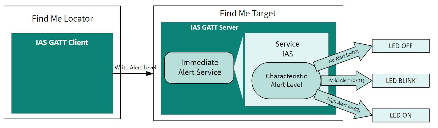
This design demonstrates the implementation of a simple Bluetooth® Immediate Alert Service (IAS)-based Find Me Profile (FMP) using the Infineon PSOC™ Edge E8 MCU with AIROC™ CYW55513 and ModusToolbox™ software environment.
The design uses the two LEDs (red LED and green LED) on the KIT_PSE84_EVAL_EPC2 kit. The red LED (USER_LED1) displays the IAS alert level – no alert (LED OFF), mild alert (LED blinking), or high alert (LED ON). The green LED (USER_LED2) indicates whether the peripheral device (
PSOC™
Edge E84) is advertising (LED blinking), connected (LED ON), or disconnected (LED OFF). In addition, a debug UART interface is used to send the Bluetooth® stack and application trace messages.
Figure 4.
Find Me profile design
Host Controller Interface - UART
In this solution where there is a separate radio controller and a host MCU, the interface between the host (for example, PSOC™ Edge E8 MCU) and the radio device (for example, CYW55513) uses the Host Controller Interface (HCI). The lower level of the Bluetooth® stack (the Controller Stack) will run on CYW55513 while the higher level of the Bluetooth® stack (the Host Stack) will run on the PSOC™ Edge along with the user application.
The HCI interface physically runs using a 4-pin UART interface. However, the PSOC™ Edge E8 MCU has multiple UARTs on it, you will still have a UART interface to print debug messages.
The controller (for example, CYW55513) runs the radio physical layer (PHY) and link layer (LL). Everything above that runs on the PSOC™ Edge E8 MCU.
Figure 5.
HCI-UART
Note:
The AIROC™ CYW55513 device also supports Wi-Fi that uses a completely independent SDIO interface for communication between the PSOC™ Edge E8 host and the AIROC™ CYW55513 device.
Create a new application
This section provides you with step-by-step instructions to create a new
ModusToolbox™
application. Before performing the steps in this section, decide whether you want to create and run the code example as-is or you want to learn how to create an application from scratch. Depending on your choice, do the following:
“Using CE directly” (evaluate existing code example (CE) directly)
Follow these sections:
- Select a new workspace
- Create a new ModusToolbox™ application
- Select PSOC™ Edge E84 MCU-based target hardware
- Create the Bluetooth® LE FindMe code example (applicable only for the “Using CE directly” flow)
Ignore the following section:
“Working from Scratch” path (use existing code example (CE) as reference only)
Follow these sections:
- Select a new workspace
- Create a new ModusToolbox™ application
- Select PSOC™ Edge E84 MCU-based target hardware
- Select a starter application and create the application (applicable only for “Working from scratch” flow)
Ignore the following section:
Launch a ModusToolbox™ application with the name “Eclipse IDE for ModusToolbox™ <version>” and get started.
Select a new workspace
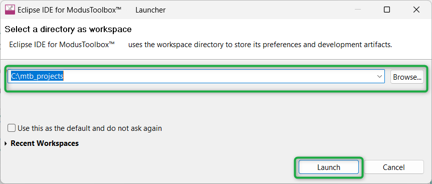
At launch,
ModusToolbox™
displays a dialog box to choose a directory as the workspace directory. The workspace directory is used to store workspace preferences and development artifacts, such as device configuration and application source code.
You can choose an existing empty directory by clicking the
Browse
button. Alternatively, you can type in a directory name to be used as the workspace directory along with the complete path, and
ModusToolbox™
will create the directory for you.
Figure 6.
Select a directory as a workspace

Create a new ModusToolbox™ application
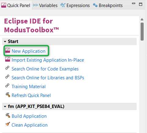
Click
New Application
(see
Figure 7
) in the Quick Panel. Alternatively, go to
and click
ModusToolbox™ Application
.
Figure 7.
Create a new ModusToolbox™ application
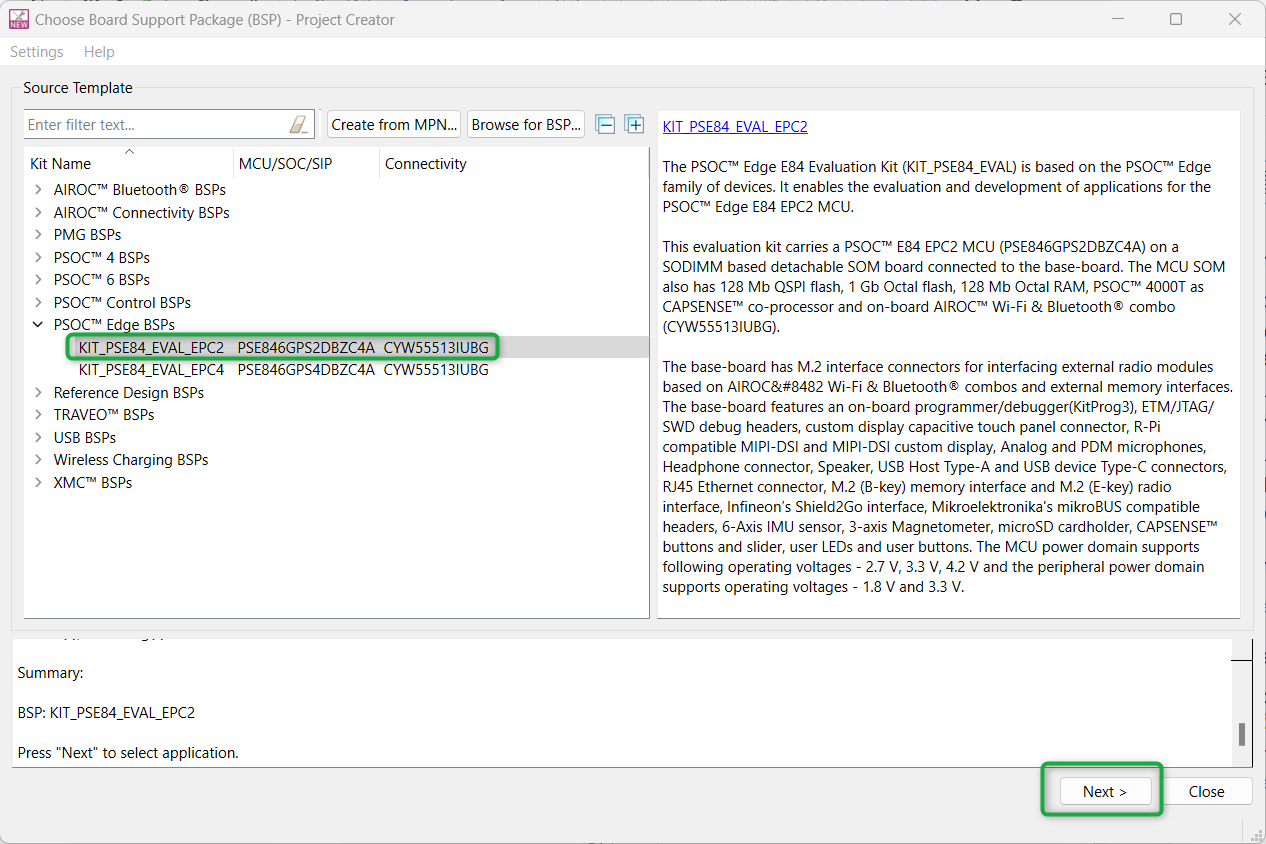
Select PSOC™ Edge E84 MCU-based target hardware
ModusToolbox™
displays the list of Infineon kits to start your application development. In this case, develop an application on the PSOC™ Edge E84 Evaluation Board that uses the
PSOC™
Edge device. Select
KIT_PSE84_EVAL
_EPC2
and click
Next
, as shown in
Figure 8
. Select
KIT_PSE84_EVAL_EPC4
if you have an EPC4 based target hardware.
Figure 8.
Choose target hardware
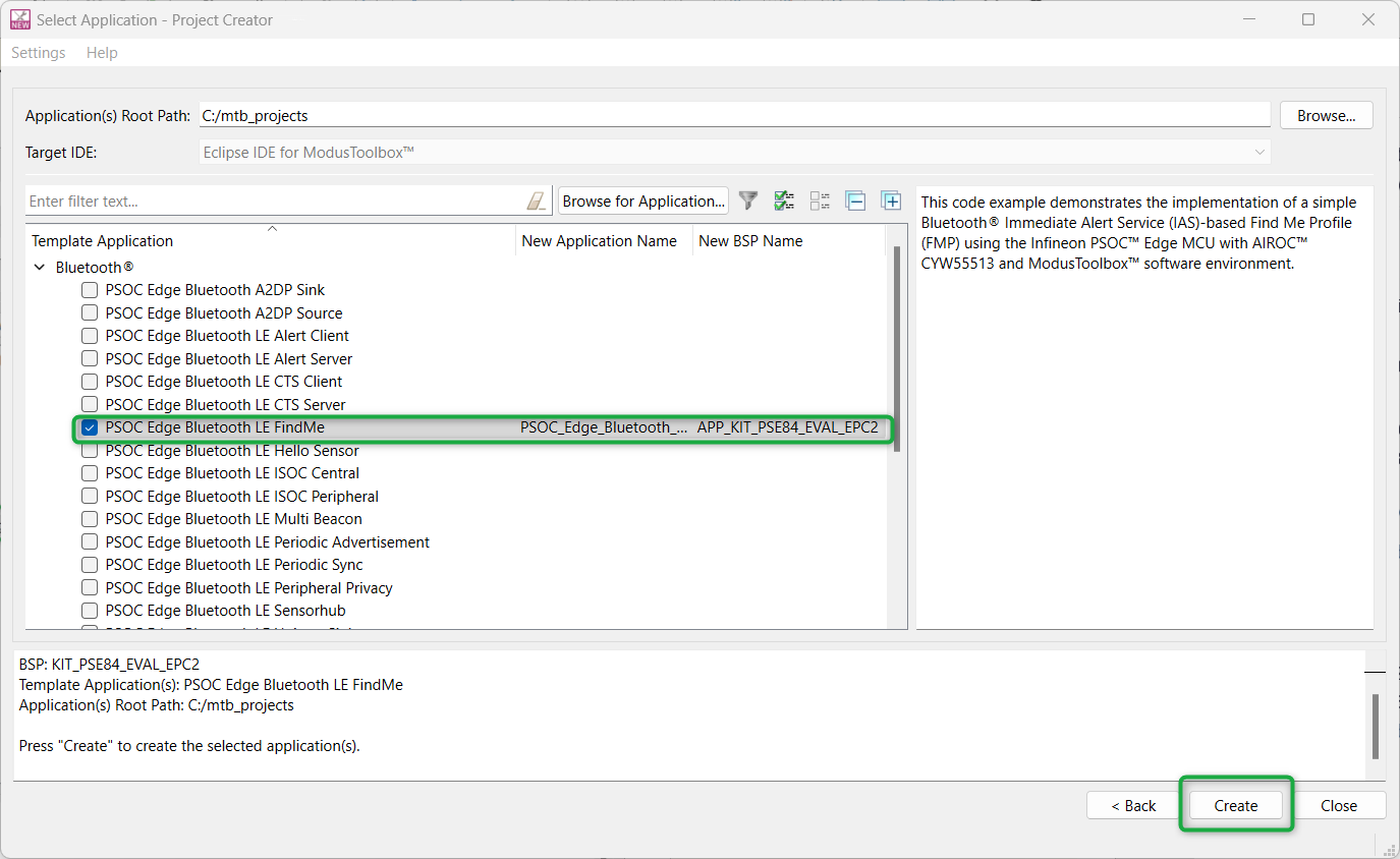
Create the Bluetooth® LE FindMe code example (applicable only for the “Using CE directly” flow)
Here, you create an existing code example (Bluetooth® LE Find Me code example) into the Eclipse IDE for
ModusToolbox™
. Do this for the “Using CE directly” flow.
Figure 9
shows the
Select Application
window of the Project Creator tool. Select the
Bluetooth® LE FindMe
application under Bluetooth®, and optionally, in the
New Application Name
field, change the name of the application. Click
Create
and wait for the application to get downloaded and created in the workspace. Click
Close
to complete the application creation process.
Figure 9.
Create Bluetooth® LE FindMe code example
Select a starter application and create the application (applicable only for “Working from scratch” flow)
You can use an existing empty application as the starting point for the “Working from Scratch” development flow. This is a minimal starter application template for PSOC™ Edge MCU devices. This example uses FreeRTOS to blink two LEDs with different frequencies respectively from the Arm® Cortex®-M33 CPU and the Arm® Cortex®-M55 CPU.
This code example has a three project structure (that is, CM33 secure, CM33 non-secure, and CM55 projects). All three projects are programmed to an external QSPI flash and executed in the XIP mode. Extended Boot launches the CM33 secure project from a fixed location in an external flash, which then configures the protection settings and launches the CM33 non-secure application. Additionally, the CM33 non-secure application enables the CM55 CPU and launches the CM55 application.
The application code of the Bluetooth® LE FindMe uses only the CM33 CPU of the PSOC™ Edge E8 MCU. Therefore, the application is written under the CM33 non-secure project (proj_cm33_ns) and the CM55 CPU (in proj_cm55) is subsequently put into Deep Sleep mode.
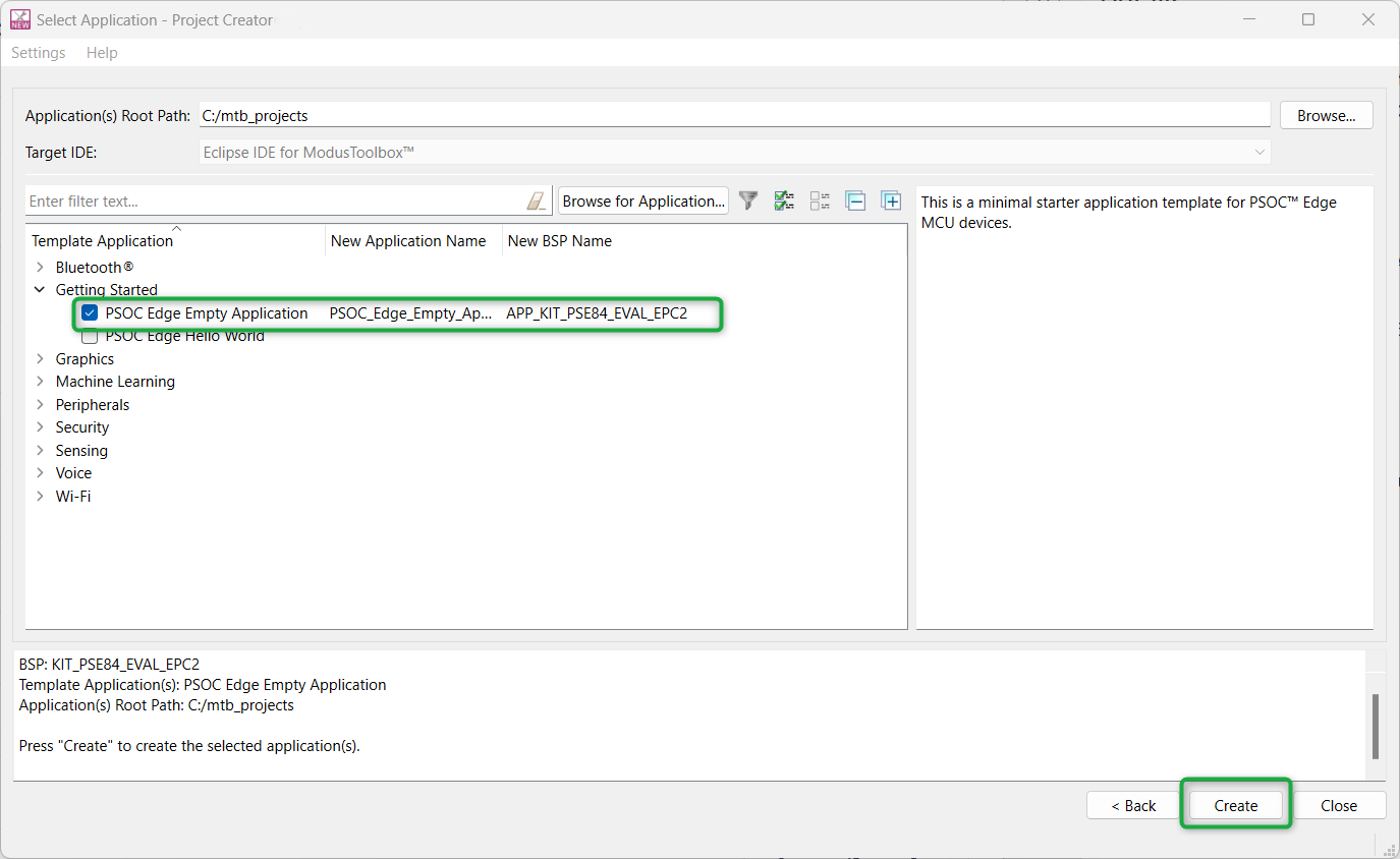
To create an Empty_app, in the
Select Application
window (see
Figure 10
), select
PSOC Edge Empty Application
. In the
Name
field, type in a name for the application if required and click
Next
; the application summary dialog appears. Click
Create
and wait for the application to get downloaded and created in the workspace. Click
Close
to complete the application creation process.
Figure 10.
Starter application window
You have successfully created a new ModusToolbox™ application for the PSOC™ Edge E84 MCU.
Configure design resources
In this step, you will configure the design resources for your application and generate the configuration code. You will also be adding the required middleware libraries.
Method | Actions |
|---|---|
“Using CE directly” (evaluate the existing CE directly) | Read and understand all steps. The CE has the resource configurations done; therefore, you need not perform any of the steps in this section |
“Working from Scratch” (use the existing CE as reference only) | Perform all steps |
Add libraries and middleware
ModusToolbox™
provides a Library Manager tool to select various middleware components for developing Bluetooth® applications. To launch the Library Manager, select the empty application (the application name will vary based on the name you provided while creating the empty_app) and in the
Quick Panel
, click
Library Manager
, as shown in
Figure 11
. Click
Add Library
to add the required libraries and middleware for your application.
Figure 11.
Open Library Manager

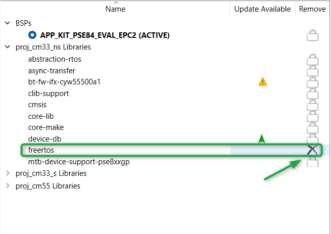
For Bluetooth® LE Find Me, follow these steps to add the required libraries:
Remove FreeRTOS from the CM33_NS project as shown in Figure 12 as it will be added as part of BTSTACK INTERGRATION, which will be added in the following steps
Figure 12.
Remove FreeRTOS
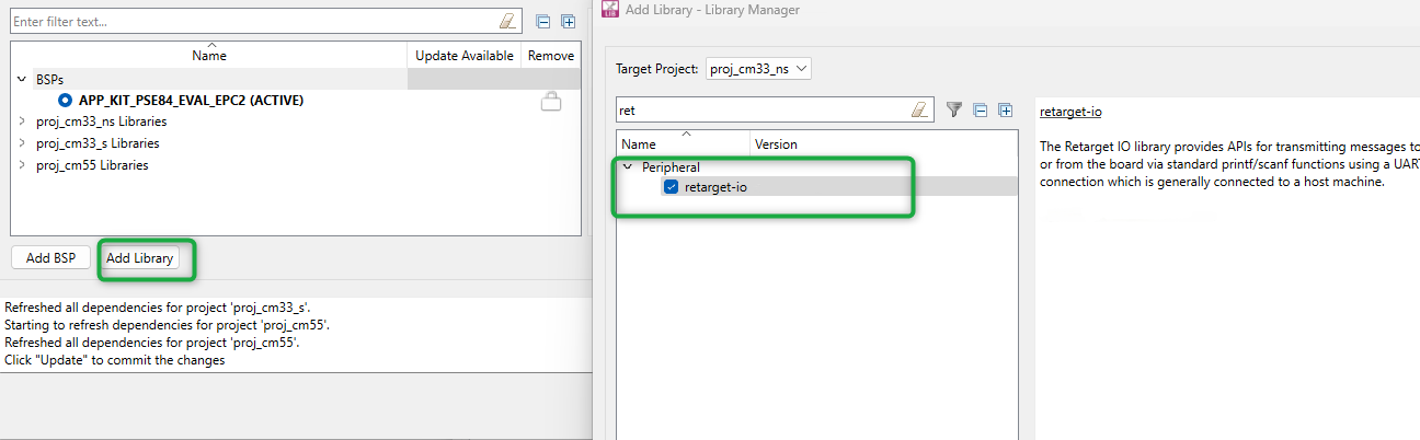
Add the
retarget-io
middleware to redirect the standard input and output streams to the UART configured by the BSP. The initialization of the middleware is done in the
main.c
file. Select
Target Project
as
proj_cm33_ns
and
Peripheral
as
retarget-io
(see
Figure 13
). While adding the required library, you can also search the library name in the
Enter filter text
box provided
Figure 13.
Add retarget-io library
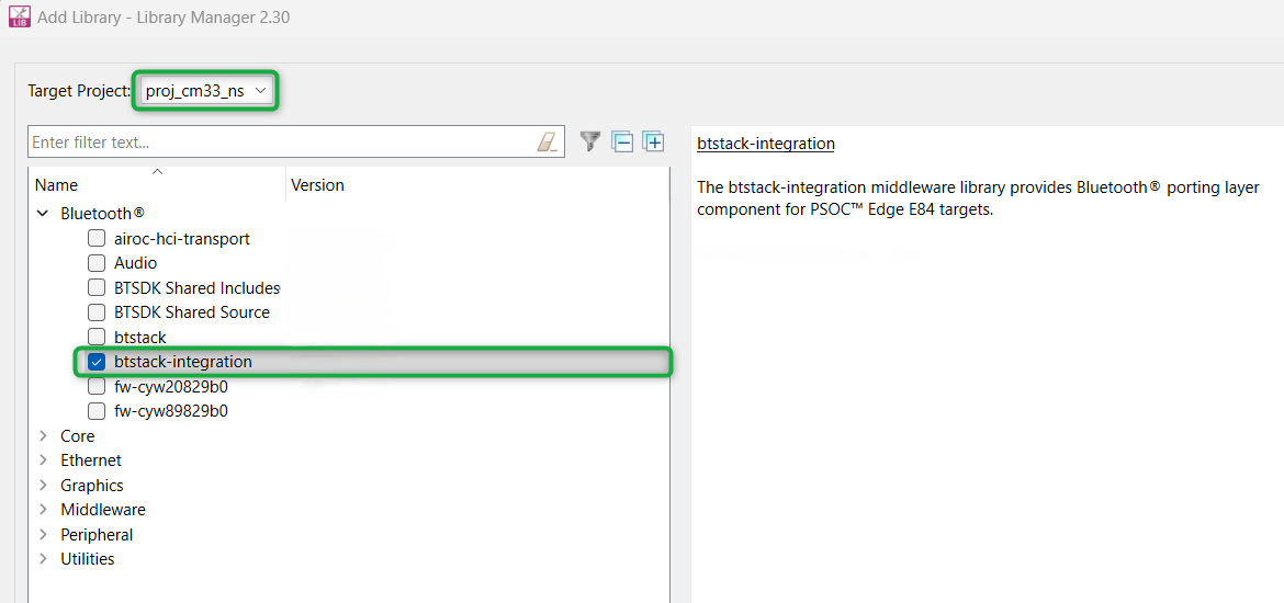
Add the
btstack integration
porting layer that sets up the physical transport required for the HCI traffic, memory, threads, and other OS constructs required by the stack library
Select
Target Project
as
proj_cm33_ns
. Under Bluetooth® drop down, select
btstack-integration
(see
Figure 14
for this option)
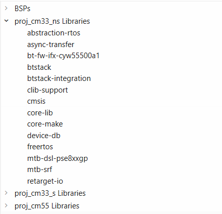
Note that selecting btstack-integration will in turn select the required btstack version, which is a software implementation of the Bluetooth® Host protocol stack. Select btstack explicitly unless a specific version is required. With btstack, btstack-integration also adds the dependency libraries abstraction-rtos and freertos
Figure 14.
Add btstack-integration middleware library
All the required libraries are selected. To add them to the project, click
OK
and then
Update
shows all the libraries selected and the respective dependency libraries. The necessary files to use the
retarget-io
and btstack integration middleware are added in the
and
folders. Additionally, the
.mtb
file is added to the
deps
folder. Similarly, you can find other libraries under the respective folder in the
mtb_shared
folder
Figure 15.
Libraries for Bluetooth® LE FindMe code example
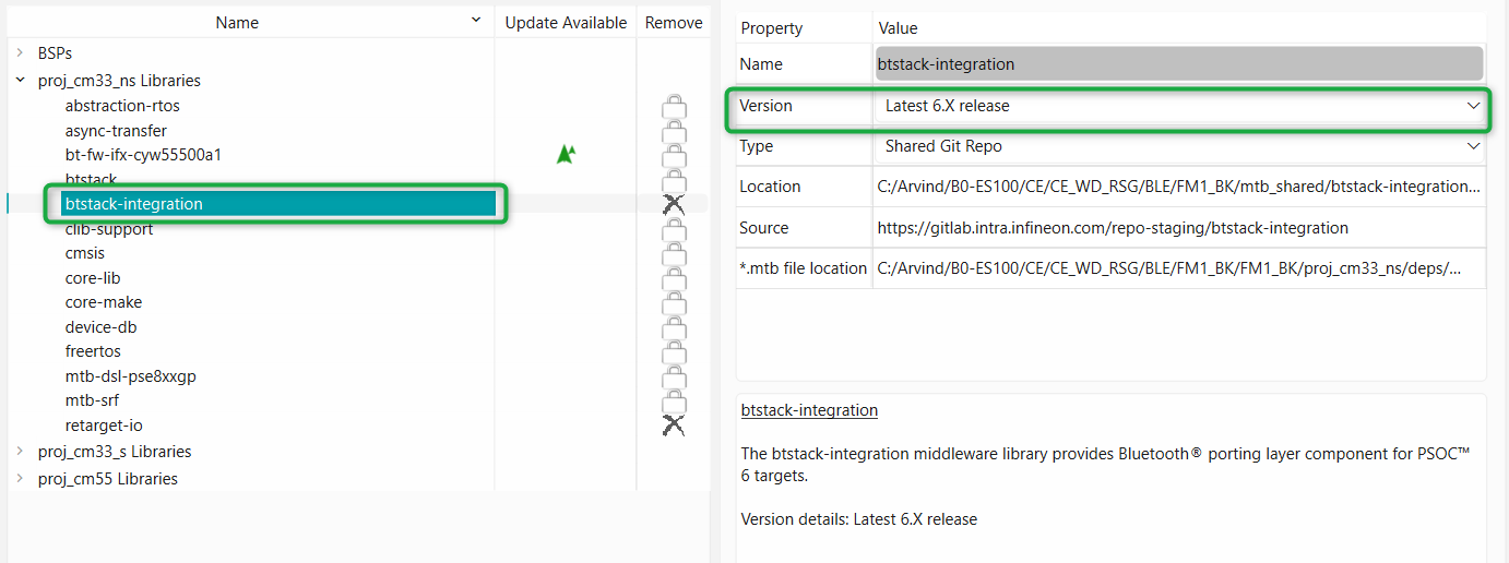
Change the version of any library by selecting the library and then click the library version, as shown in
Figure 16
Figure 16.
Change library version
Device Configurator
ModusToolbox™ provides a Device Configurator tool to configure the communication, digital, and system peripherals. For the Find Me application, configure the Timer Counter Pulse Width Modulation (TCPWM) peripheral to control the USER LEDs on the kit. In this application,
USER LED1 (red LED) indicates the IAS alert level characteristic when the device is connected to a peer device
USER LED2 (green LED) indicates the advertising/connected state of the Bluetooth® LE peripheral device
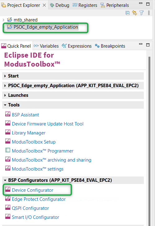
Launch the Device Configurator by selecting the Empty Application (the application name will vary based on the name you provided while creating the empty app) and click the Device Configurator option under BSP Configurators as shown in
Figure 17
.
Figure 17.
Open Device Configurator
Follow these steps to add the required configurations for the PWMs:
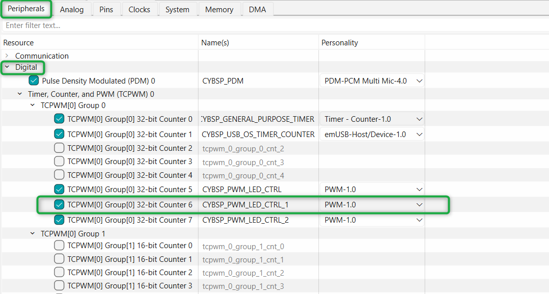
Steps to configure PWM instance for USER LED2 (green LED):
Navigate to the
Peripherals
section and expand
Digital
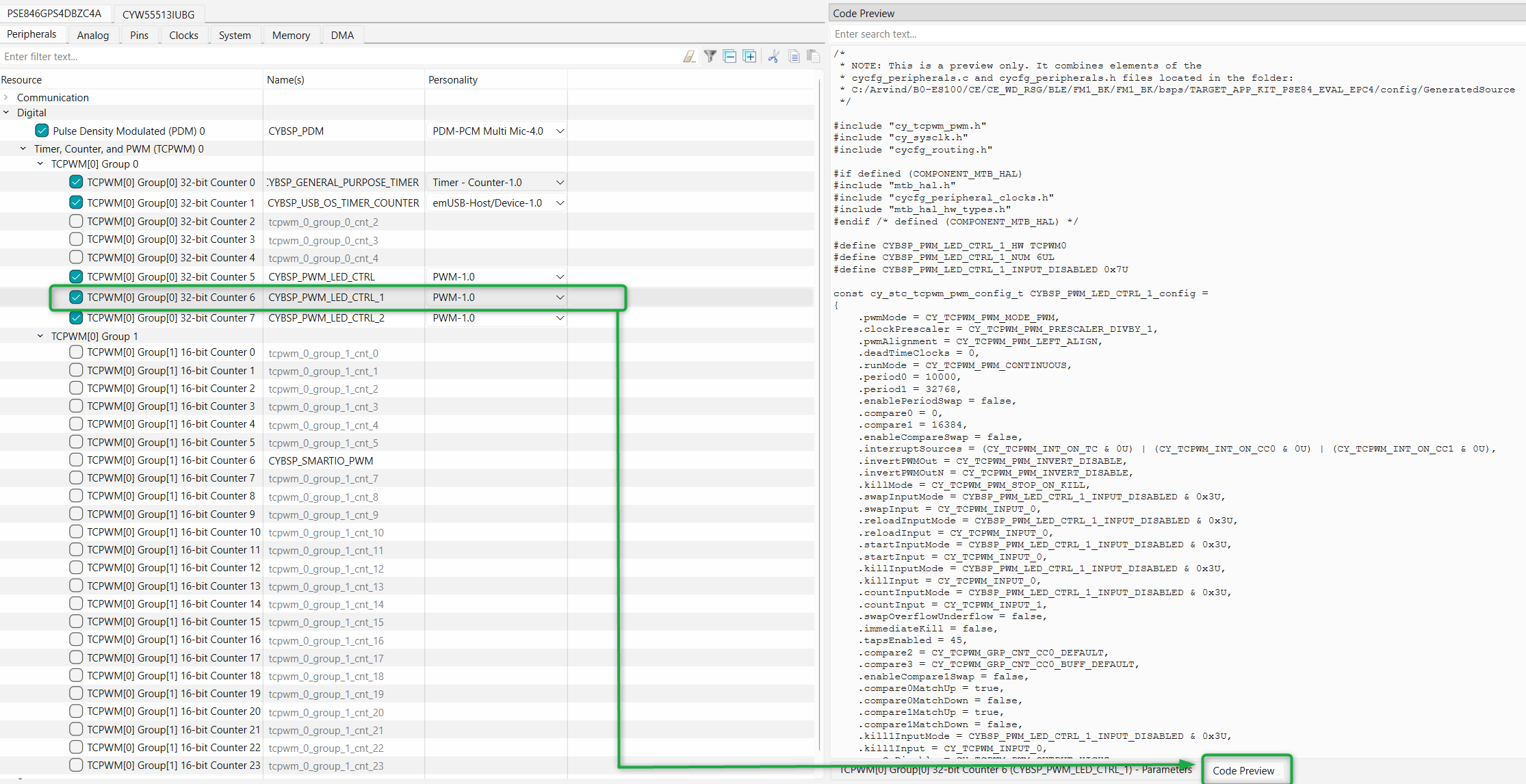
. Select the
TCPWM[0] Group[0] 32-bit Counter 6
and choose
PWM
from the available options. Name this instance as "CYBSP_PWM_LED_CTRL_1" as shown in
Figure 18
. Do not alter this name, as it is used to generate macros in the source code and is referenced in the application code during PWM initialization. If you prefer to use a different name, ensure that you update the code accordingly
Figure 18.
Select and name PWM instance for USER LED2
On the right panel, configure the PWM settings as follows:
Set the
PWM mode
to PWM with a period value of 10000 and a
Compare 0
value of 0
Under the
Inputs
section, select the
Clock Signal
option and choose the 16.5 - bit divider (CYBSP_SMARTIO_PWM_CLK_DIV)
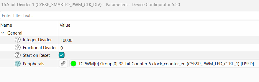
Next, select the pin symbol under the clock option and configure the divider to 10000, resulting in a frequency of 10 kHz. Deselect and disable other unused peripherals shared by the same clock or you can also choose a different clock. Then, click the pin symbol again to return to the
Peripherals
tab
On the
Outputs
section, select the pin symbol in
PWM (line)
and choose P16[6] (CYBSP_USER_LED2, CYBSP_USER_LED_GREEN). A prompt will appear requesting that you change the drive mode for the selected LED. Click
Fix
and proceed to change the
Drive Mode
to "Strong Drive. Input buffer off'
Figure 19.
PWM settings for USER LED 2
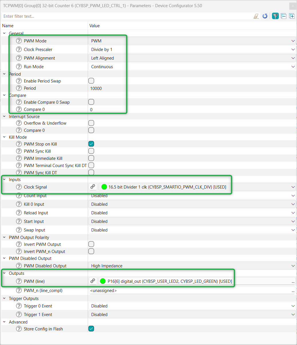
Figure 20.
Clock configuration for PWM for USER LED2
Steps to configure PWM instance for USER LED1 (red LED):
Follow the similar steps used to configure PWM for USER LED2 above with the following changes
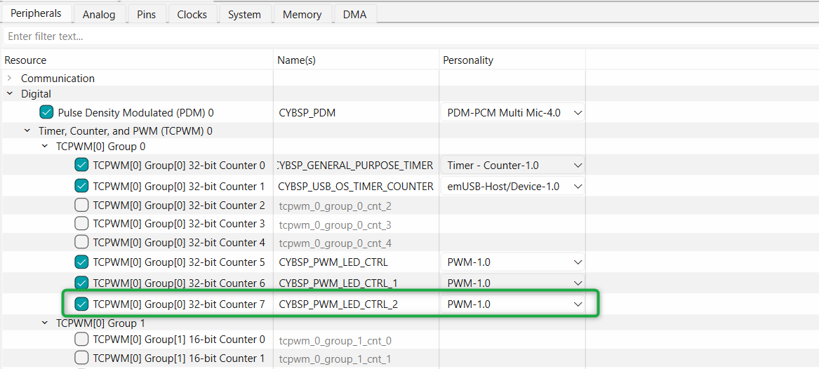
Select the
TCPWM[0] Group[0] 32-bit Counter 7
option and choose
PWM
from the available options and name the instance "CYBSP_PWM_LED_CTRL_2" as shown in
Figure 21
Figure 21.
Select and name PWM instance for USER LED1
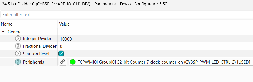
Select "24.5 bit Divider 0 clk (CYBSP_SMART_IO_CLK_DIV) and deselect and disable other unused peripherals shared by the same clock or you can also choose a different clock
In the
Outputs
section, select the pin symbol in
PWM (line)
and choose P16[7] (CYBSP_USER_LED1, CYBSP_USER_LED_RED). A prompt will appear requesting that you change the drive mode for the selected LED. Click
Fix
and proceed to change the
Drive Mode
to "Strong Drive. Input buffer off"
Figure 22.
PWM settings for USER LED 1
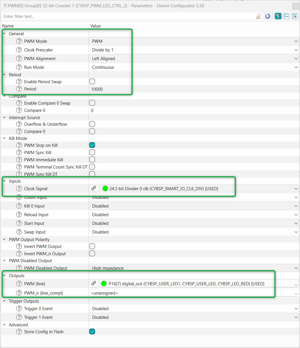
Figure 23.
Clock configuration for PWM for USER LED1
Once both the PWM instances are configured by following the earlier steps, save and close the Device Configurator tool. These configurations are generated as part of code in the
.
You can also see the code preview of each configuration by selecting the code preview in the Device Configurator as shown in
Figure 24
.
Figure 24.
Configuration code preview
Apart from these configurations, which are done manually by following the earlier steps. Other configurations for USER LED, Debug UART, Bluetooth® UART. etc. are done in the default board support package (BSP), which is generated as part of an empty application. You can view them by opening the Device Configurator anytime.
Bluetooth® Configurator
The Bluetooth® peripheral has an additional configurator called the Bluetooth® Configurator that is used to create the Bluetooth® LE configuration structure and GATT database for the application. The Bluetooth® LE configuration structure generated will be used by the application during stack initialization.
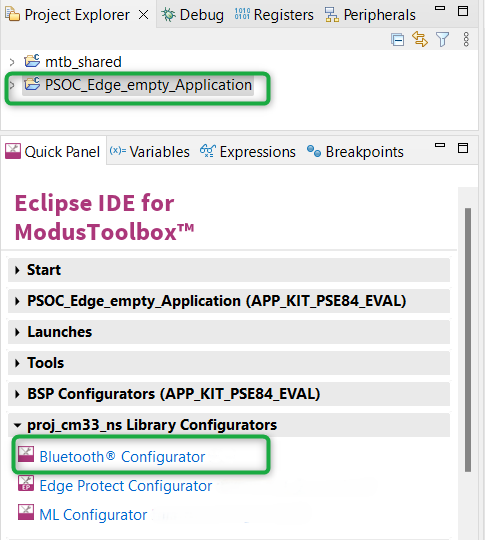
For the Find Me Profile application, you need to generate a GATT database and Bluetooth® settings to initialize the host btstack corresponding to the Find Me Target role of the PSOC™ Edge E84 device. To launch the Bluetooth® Configurator, in the Quick Panel, click on the Application and then click
Bluetooth® Configurator
under
proj_cm33_ns Library Configurators
section, as shown in
Figure 25
Figure 25.
Open Bluetooth® Configurator
General
Select Bluetooth® mode as "Single mode LE".
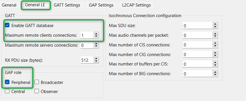
General LE
Set the General LE properties, as shown in Figure 26.
Under the General LE tab, select the Enable the GATT database checkbox
Set Maximum remote client connections to "1". This will configure the Bluetooth® LE stack appropriately
Additionally, under the General LE tab, confirm that the Peripheral checkbox is selected as the GAP role . This sets the device to act as a Bluetooth® LE Peripheral device and respond to central device requests
Figure 26.
General LE configuration
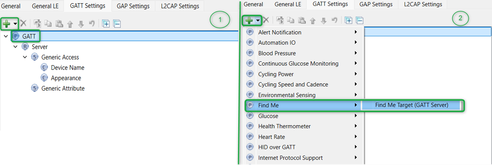
GATT settings
To add the Find Me Target profile, select the GATT Settings tab. Click GATT profile , and then click the + icon. Select the Find Me Target (GATT Server) profile from the dropdown menu, as shown in
Figure 27
Figure 27.
Adding Find Me Target profile
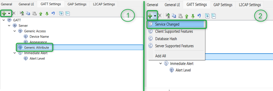
Similarly, select Generic Attribute , click the + icon, and then select the Service Changed characteristics from the dropdown menu as shown in Figure 28
Figure 28. Adding Service Changed characteristics
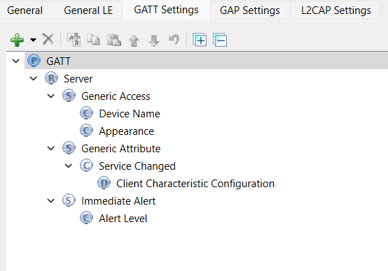
shows the GATT database view once the Find Me Target Server is added. Note that the Immediate Alert Service corresponding to the Find Me Target profile is added. Click
in the Configurator window or click
Save
. The configurator stores the GATT database in the source files
cycfg_gatt_db.c
and
cycfg_gatt_db.h
in the
GeneratedSource
folder.
Figure 29.
Final GATT database view
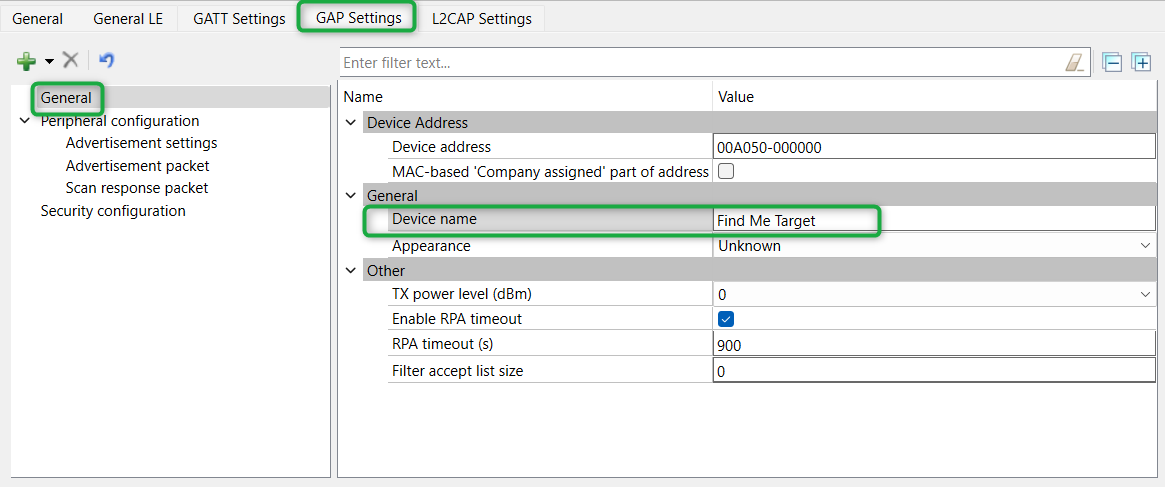
GAP settings
There is a series of panels to cover GAP settings. The left-side menu provides access to all the panels.
General GAP Settings
Click the
GAP Settings
tab to display GAP options. The
General
panel appears by default. Enter
Find Me Target
as the device name as shown in Figure 30
All other general settings use default values. This configures the device name that appears when a host device attempts to discover your device
Figure 30. General GAP settings
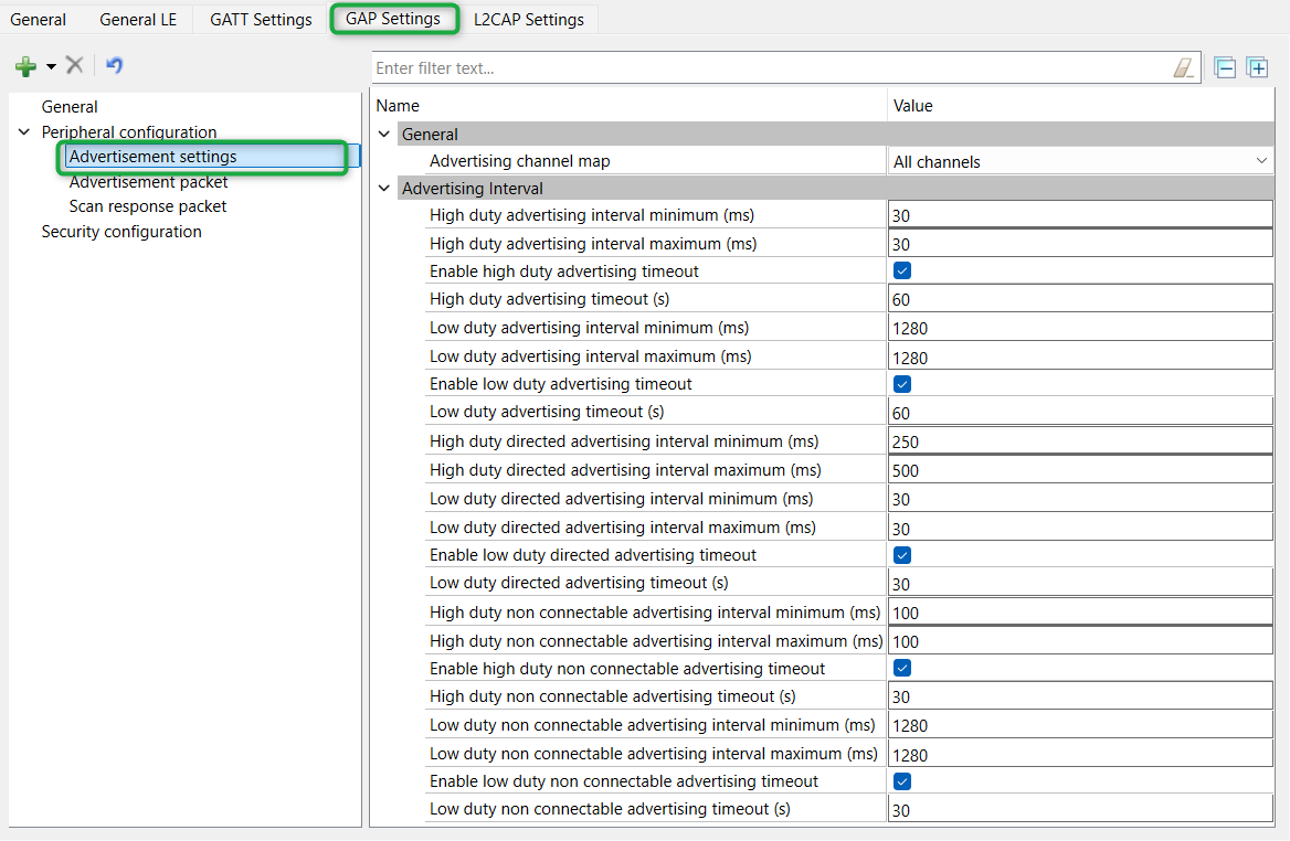
- GAP advertisement settings
Click Advertisement settings under the Peripheral configuration . Default values work for this application (see Figure 31 ). It uses a high-duty advertising interval of 30 ms and a low-duty advertising interval of 1280 ms. High-duty advertising allows quick discovery and connection but consumes more power due to increased RF advertisement packets
Figure 31. GAP advertisement settings
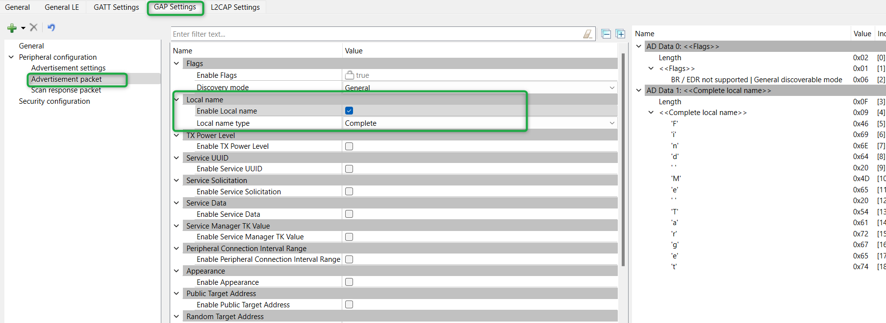
- GAP advertisement packet settings
In this step, you specify the data for the advertisement packet (see Figure 32 )
Click Advertisement packet under Peripheral configuration
The application uses a General discovery mode
Select the Enable Local name checkbox to include it in the advertisement packet and the local name type as Complete
This configures the advertisement packet of the device. As you add items, the structure and content of the advertisement packet appear on the right-side of the configuration panel
Figure 32. GAP advertisement packet settings
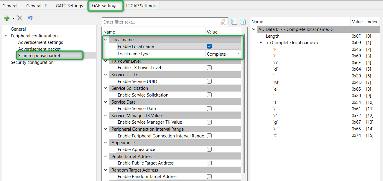
- Scan response packet settings
In this step, you specify the data for the scan response packet. Note that as you add values, the structure, and content of the scan response packet appear on the right-side of the configuration panel
Click Scan response packet under Peripheral configuration
Select the Enable Local name checkbox to include that item in the response as shown in Figure 33
Figure 33. GAP scan response packet settings
After the successful configuration, click
Save
and close the configurator.
You can find this design.cybt file under proj_cm33_ns and code files generated for these configurations under proj_cm33_ns/GeneratedSource .
The following files will be generated in this
GeneratedSource
folder:
- cycfg_bt_settings.c
- cycfg_bt_settings.h
- cycfg_gap.c
- cycfg_gap.h
- cycfg_gatt.db.c
- cycfg_gatt.db.h
- cycfg_bt.timestamp
Write the application code
At this point in the development process, you have created an application, added required middleware libraries and generated the configuration code, including the Bluetooth® LE GATT database. This part examines the application code that implements the Find Me Target functionality.
Method | Actions |
|---|---|
“Using CE directly” (evaluate existing code example (CE) directly) | Ignore Step 1 and Step 2. The CE already has all the necessary source files added. Read through the Firmware description section to understand the firmware design |
“Working from scratch” (use existing code example (CE) as reference only) | Perform Step 1 and Step 2. Also, read through the Firmware description section to understand the firmware design |
The application code must do the significant tasks as follows:
Perform system initialization, including the Bluetooth® stack
Implement Bluetooth® stack event handler functions for different events, such as an advertisement, connection, and attribute read/write requests
Implement user interface logic to update the LED state on the kit based on the events triggered
Note:
The empty application of the PSOC™ Edge E8 MCU has a three project structure (proj_cm33_ns, proj_cm33_s, and proj_cm55). The application code of the Bluetooth® LE Find Me is to be written on the proj_cm33_ns project that uses the M33 core and subsequently the proj_cm55 project that uses the M55 core is put into Deep Sleep mode.
STEP 1: Add files to your project (required only for the “Working from Scratch” flow).
Clone or download the Bluetooth®LE Find Me application code from the Infineon GitHub repository to a local repository
Copy and replace the following files/folder under proj_cm33_ns to your proj_cm33_ns folder of the "Empty_App" inside the ModusToolbox™ workspace folder
- source/main.c
- source/app_bt/app_bt_utils.c
- source/app_bt/app_bt_utils.h
- FreeRTOSConfig.h
- source/app_retarget_io/retarget_io_init.c
- source/app_retarget_io/retarget_io_init.h
Copy and replace the main.c file from the proj_cm55 folder of the same code example to your proj_cm55 folder of "Empty_App" inside the ModusToolbox™ workspace folder
STEP 2: Add the values to the variables in the
Makefile
of proj_cm33_ns of the PSOC_Edge_Empty_app as follows (required only for the “Working from Scratch” flow).
COMPONENTS+=FREERTOS RTOS_AWARE WICED_BLE
The components FREERTOS, RTOS_AWARE, and WICED_BLE are required to include the files from FreeRTOS and BTSTACK libraries for compilation
DEFINES+=CYBSP_BT_PLATFORM_CFG_BAUD_FEATURE=3000000
The above defines is required to set the Bluetooth® feature baudrate to 3 MHz. This can be varied from 115200 to 3000000 based on the requirement
DEFINES+=CY_RETARGET_IO_CONVERT_LF_TO_CRLF CY_RTOS_AWARE
CY_RETARGET_IO_CONVERT_LF_TO_CRLFis provided by the retarget-io library to enable conversion of the line feed (LF) into a carriage return followed by the line feed (CR and LF) on the output direction (STDOUT)CY_RTOS_AWARE must be defined to inform the Peripheral Driver Library (PDL) that an RTOS environment is being used
Firmware description
This section explains the application firmware of the Find Me application. The important source files relevant to the user application-level code to this code example are listed in
Table 4
.
Files | Description |
|---|---|
GeneratedSource/cycfg_gatt_db.c GeneratedSource/cycfg_gatt_db.h | These files are located in the GeneratedSource folder under the application folder. They contain the GATT database information generated using the Bluetooth® Configurator tool |
source/app_bt/app_bt_utils.c source/app_bt/app_bt_utils.h | These files consist of the utility functions that will help to debug and develop the applications easier with much more meaningful information |
source/main.c | This file contains the function that is the entry point for execution of the user application code after device startup. Additionally, it contains the code for the Bluetooth® stack event handler functions and code for the application user interface (in this case, the LED) functionality |
source/app_retarget_io/retarget_io_init.c source/app_retarget_io/retarget_io_init.h | These files contain the initialization routine for the retarget-io middleware |
design.cybt | This file is used by the application to specify Bluetooth® configurations and the GATT database using the GUI tool bt-configurator |
FreeRTOSConfig.h | This file is provided by the FreeRTOS library and copied into the application directory. This file has settings for the FreeRTOS Kernel. The application can modify the settings based on the use case |
Makefile | This file contains settings for application build |
User application code entry
The
main.c
file contains the
int main()
function. This function is the entry point for executing the user application code after device initialization is complete. In this code example, this function does the following:
Initializes the BSP that includes the initializing the target hardware. For example, it initializes system power management and device configuration. It performs other platform-specific initialization. If the BSP initialization fails, the app enters CY_ASSERT. If you are debugging the application, CY_ASSERT acts as a breakpoint
Initializes retarget-io to use the debug UART port to view the trace messages and print messages on the debug UART using the
printffunctionInitializes the tickless idle timer instance of the CM33 CPU. This lptimer instance is initialized and setup and an object is created and passed to the abstraction RTOS that implements the tickless idle mode. This is done to allow the device to enter into Seep Sleep when an idle task is executed
Registers a Bluetooth® stack management callback function by calling
wiced_bt_stack_init()
. The stack management callback function then typically controls the rest of the application based on Bluetooth® events. Typically, only a minimal application initialization is done in the
int main()function. Most application initialization is done in the stack callback function once the Bluetooth® stack is enabled. The stack callback functionapp_bt_management_callback()is defined in main.c . A callback function is a function that is called by another function when a particular event happens. If the stack initialization fails, the application enters CY_ASSERTEnables the CM55 core. The RTOS task in the CM55 core is suspended which puts the CPU to Deep Sleep because only the CM33 core is used to run the Bluetooth® LE application
After successful initialization, the application starts the FreeRTOS scheduler
Bluetooth® stack events
The
main.c
file contains the application code logic to handle the different types of events generated by the stack. At a high level, the following two categories of events need to be handled:
Bluetooth® stack management events
GATT events
Bluetooth® stack management events
The callback function
app_bt_management_callback()
handles events such as Stack Enabled, Advertisement State Change, and Security-related events, such as Pairing and Key Exchange. This callback function is registered as a part of the
int main
()
function. See the
wiced_bt_management_evt_t
definition in
wiced_bt_dev.h
file for the list of management events. It is not required for the application code to handle all the management events. The events handled depend on the application requirements.
shows the execution logic for the stack management event handler in this code example. Additionally, note that
Figure 34
shows only the two management events (BTM_ENABLED_EVT and BTM_BLE_ADVERT_STATE_CHANGED_EVT) that are handled in the BTSTACK management callback function.
Figure 34.
Bluetooth® stack management event handler function flow
All the application code initialization is done only after the Bluetooth® stack has been enabled successfully by calling the
le_app_init()
function.
The
le_app_init()
function defined in the
main.c
file performs the following initialization tasks:
Initializes two PWM blocks used to control IAS LED and Advertisement LED
Disables pairing by calling
wiced_bt_set_pairable_mode()
. For this application, the pairing feature is not used
Configures the advertisement packet data by calling
wiced_bt_ble_set_raw_advertisement_data()
. Look at this function definition in the code example to understand how to configure the elements of an advertisement packet
Registers the callback function to handle GATT events (
le_app_gatt_event_callback()
) by calling
wiced_bt_gatt_register()
Initializes the GATT database (gatt_database) defined in cycfg_gatt_db.c by calling
wiced_bt_gatt_db_init()As the final step of the initialization process, the device starts advertising by calling
wiced_bt_start_advertisements()
GATT events
The
le_app_gatt_event_callback()
function handles GATT events, such as connection and attribute request events. This
function is registered with a call to
wiced_bt_gatt_register()
from the
le_app_init()
function. Refer to the
wiced_bt_gatt_evt_t
definition in the wiced_bt_gatt.h file for the list of GATT events. It is not required for the application code to handle all the GATT events. The events handled depend on the application requirements.
Figure 35
shows the execution logic for the GATT event handler in this code example.
Figure 35
shows only two GATT events (GATT_CONNECTION_STATUS_EVT and GATT_ATTRIBUTE_REQUEST_EVT) that are handled in the function.
Figure 35.
GATT event handler
At this point, it is pertinent to discuss the GATT_ATTRIBUTE_REQUEST_EVT event, which is used to process the GATT Attribute read/write operations.
Figure 35
gives information on the functions called in the case of a read or write operation. In this code example, when the Find Me Locator updates the IAS Alert Level characteristic on the PSOC™ Edge Bluetooth® LE device, GATT_ATTRIBUTE_REQUEST_EVT is triggered, which in turn calls the series of functions related to the attribute write request. At the end of the write operation, the
app_ias_alert_level ()
function in the GATT database in the
cycfg_gatt_db.c
file gets updated with the alert level set by the Find Me Locator, and the LED is set appropriately to the alert level.
Summary of Bluetooth® stack events
Figure 36
shows
the function call chart summarizing the sequence of function calls for different stack
events for this application. All these functions (except
adv_led_update()
) are defined in the
app_bt_event_handler.c
file. See the
source code to understand the implementation details of these functions.
Figure 36.
Bluetooth® stack events function call chart
User interface logic
The
main.c
file contains the application code to handle the user interface logic. The design uses the following two LEDs for the user interface:
USER_LED2 (green LED) on the kit indicates the advertising/connected state of the Bluetooth® LE peripheral device. If the device is not advertising, USER_LED2 is in the OFF state. If the device is advertising (until timeout), the LED is in a blinking state. The LED is always in the ON state when connected to the peer device. See the
adv_led_update ()
function for implementation details. The
adv_led_update ()
function is called from two places in the application code:
The
app_bt_management_callback()
function updates USER_LED2 when the advertisement state changes (stack management event
BTM_BLE_ADVERT_STATE_CHANGED_EVT
)
The
le_app_connect_handler()
function updates USER_LED2 when the connection state changes
USER_LED1 (red LED) on the kit indicates the IAS alert level characteristic when the device is connected to a peer device. When connected to a peer device, USER_LED1 is in the OFF state for low alert, blinking state for mid-alert, and ON state for high alert. See the
ias_led_update()
function for implementation details. The
ias_led_update()
function is called from two places in the application code:
The
le_app_set_value()
function updates USER_LED1 when an attribute write request to the IAS Alert Level characteristic is done from the client side
The
le_app_connect_handler()
function drives USER_LED1 to the OFF state when a disconnection occurs
Note that both the user LEDs are controlled by using Pulse Width Modulation (PWM) technique by setting the compare0 value, which in turn varies the duty cycle. The
Cy_TCPWM_PWM_SetCompare0()
function is used to set the compare value to change the duty cycle to 0 (off state), 50 (blinking state), and 100 (on state) to control the LEDs. The PWM configuration for the USER LEDs are done using the Device Configurator. See the
Device Configurator
section for details on PWM configurations.
Build, program, and test your design
This section shows how to build and program the Bluetooth® LE Find Me application on the PSOC™ Edge E84 Evaluation Kit. It also explains how to test the Find Me Profile Bluetooth® Low Energy design using the
AIROC™
Bluetooth® Connect mobile app, and the USB – UART serial interface to view the Bluetooth® stack and application trace messages.
At this point, it is assumed that you have followed the previous steps in this application note to develop the Find Me Profile application.
Method | Actions |
|---|---|
“Using CE directly” (evaluate existing Code Example (CE) directly) | Perform all the steps in this section |
“Working from Scratch” (use existing Code Example (CE) as reference only) | Perform all the steps in this section |
Note:
To understand the build and program process of a simpler application, see the Getting started with PSOC™ Edge E8 MCU application note that explains how to run a simple hello world application on the KIT_PSE84_EVAL_EPC2/KIT_PSE84_EVAL_EPC4.
To build, program and test the application, do the following:
Connect the kit to your PC using the provided USB cable
The USB – UART serial interface on the kit provides access to the UART interface of the PSOC™ Edge E84 device. Use your favorite serial terminal application (
Tera Term
is used in this design) and connect to the USB – UART serial port. Configure the terminal application to access the serial port using the following settings:
Baud rate: 115200 bps; Data: 8 bits; Parity: None; Stop: 1 bit; Flow control – None; New line for receiving data: Line Feed (LF) or auto setting
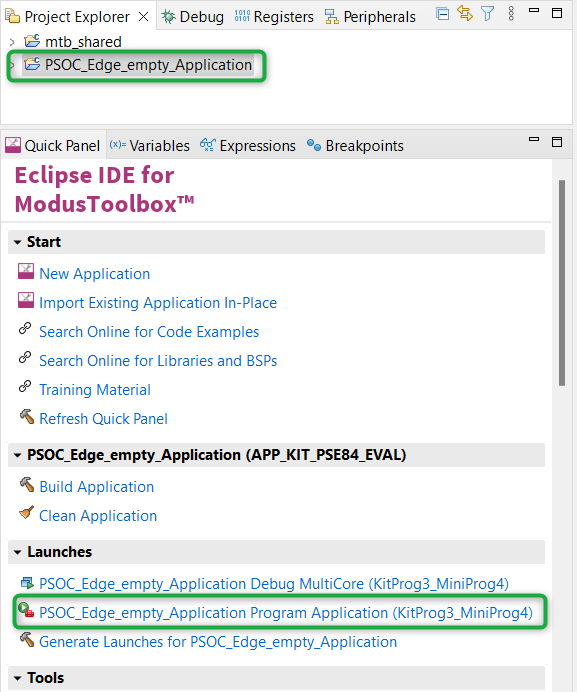
Build and Program the Application: In the Project Explorer, select the
<App Name>
project. In the Quick Panel, under the
Launches
dropdown list, click the
<App Name> Program (KitProg3_MiniProg4)
configuration, as shown in
Figure 37
Figure 37.
Build and program the application
Note:
You can also use the command-line interface (CLI) to build and program the application. See the Build system section in the
ModusToolbox™ tools package user guide
. This document is located in the
/docs_<version>/folder
in the ModusToolbox™ installation directory
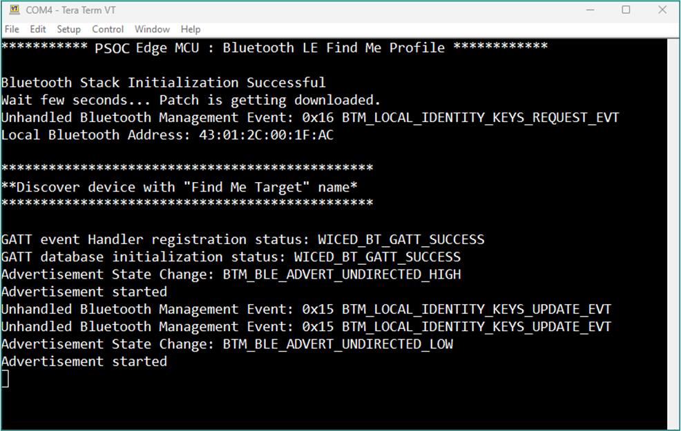
After programming, the application starts automatically. Wait for the device to make all the required connections and observe the messages on the UART terminal as shown in
Figure 38
Figure 38.
Log messages on UART terminal after programming
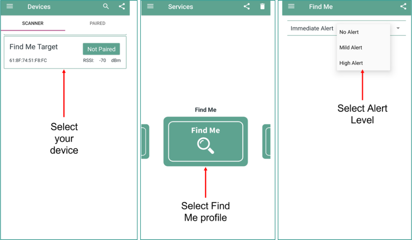
To test using the AIROC™ Bluetooth® Connect mobile app, do the following (see equivalent AIROC™ Bluetooth® Connect app screenshots in
Figure 39
(iOS) and
Figure 40
)(Android):
Turn ON Bluetooth® on your Android or iOS device
Launch the AIROC™ Bluetooth® Connect app
USER_LED2 (green LED) starts blinking if the advertising is started. Advertising will stop after 120 seconds if a connection is not established and USER_LED2 (green LED) will turn off
Swipe down on the AIROC™ Bluetooth® Connect app home screen to start scanning for Bluetooth® LE peripherals; your device (“Find Me Target”) appears in the AIROC™ Bluetooth® Connect app home screen. Select your device to establish a Bluetooth® LE connection. Once the connection is established, USER_LED2 (green LED) changes from the blinking state to the always ON state
Select the 'Find Me Profile' from the carousel view
Select an
Alert Level
value on the Find Me Profile screen. Observe the state of USER_LED1 (red LED) on the device; it changes based on the alert level
Figure 39.
AIROC™ Bluetooth® Connect app on iOS device
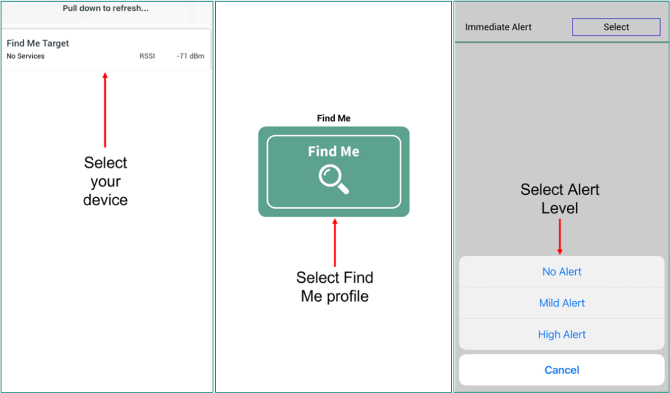
Figure 40.
AIROC™ Bluetooth® Connect app on Android device
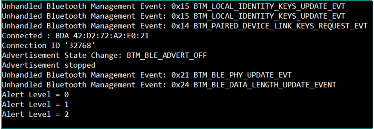
Observe the messages on the UART terminal based on the Alert Level selected as shown in
Figure 41
Figure 41.
Log messages on UART terminal based on the alert level selected
You have successfully developed and tested a simple Bluetooth® LE application for the
PSOC™
Edge E84 device using Eclipse IDE for
ModusToolbox™
.
Wi-Fi Secure TCP client example
Note:
The MCU Wi-Fi connectivity design using Eclipse IDE for the ModusToolbox™ software is developed for the PSOC™ Edge E84 Evaluation Kit (KIT_PSE84_EVAL_EPC2/KIT_PSE84_EVAL_EPC4) that has PSOC™ Edge E84 MCU interfaced with AIROC™ CYW55513 Wi-Fi & Bluetooth® combo chip. You can use other PSOC™ 6 kits to develop this example by selecting the appropriate kit while creating the application. Also, adapt the prerequisites and other sections, which are specific to the PSOC™ Edge E84 device according to the PSOC™ 6 kit that you are using. See the
References
section for documents related to the kit.
This section provides step-by-step instructions to build a simple Wi-Fi-based application for the PSOC™ Edge E84 device using the Eclipse IDE for ModusToolbox™. In this design, the TCP client establishes a secure connection with a TCP server through an SSL handshake.
The steps covered in this section are:
Create a new application
Configure design resources
Write the application code
Build, program, and test your design
These instructions require that you use a particular code example (
Wi-Fi Secure TCP client
in this case). However, the extent to which you use the code example (CE) depends on the method you follow through these instructions.
lists two defined methods to follow through these instructions depending on what you want to learn.
Method | Best for |
|---|---|
“Using CE directly” (evaluate existing code example (CE) directly) | If you are new to the tool or device, and want to see how it all works quickly |
“Working from Scratch” (use existing code example (CE) as a reference only) | If you want the hands-on experience to learn to develop PSOC™ Edge E84-based Wi-Fi applications in ModusToolbox™ |
What you need to do for each option is clearly defined at the start of each part of the instructions.
If you start from scratch and follow all instructions in this application note, you must use the code example as a reference while following the instructions. Working from scratch helps you learn the design process and takes more time. Alternatively, you can evaluate the existing code example directly to get acquainted with the PSOC™ Edge E84 development flow in a short time.
It would help if you started reading from
Prerequisites
and also go through the
Firmware description
section in both the cases.
Prerequisites
Ensure that you have the appropriate development kit for the PSOC™ Edge E84 MCU product line, which is PSOC™ Edge E84 Evaluation Kit (
KIT_PSE84_EVAL_EPC2
). Note that KIT_PSE84_EVAL_EPC2 is the default BSP, which supports EPC2 based MCU and you can optionally use
KIT_PSE84_EVAL_EPC4
if you have an EPC4 based MCU
See the
AN235935 - Getting started with PSOC™ Edge E8 MCU on ModusToolbox™ software
application note for hardware and software prerequisites
Additionally,
Ensure that the
Python interpreter
is installed on the PC. Python v3.12.1 is used in this design
Install any terminal emulator.
Tera Term
is used/shown in this design
About the design
This design demonstrates the implementation of a secure TCP client using the Infineon PSOC™ Edge E8 MCU with AIROC™ CYW55513 and ModusToolbox™ software environment.
In this design, the TCP client establishes a secure connection with a TCP server through an SSL handshake. After the successful completion of the SSL handshake, the TCP client turns the user LED ON or OFF based on the command received from the TCP server. The Wi-Fi device can be brought up in either STA interface or Soft AP interface mode. Additionally, this code example can be configured to work with IPv4 or link-local IPv6 addressing mode.
During the SSL handshake, the client presents its SSL certificate (self-signed) for verification and also verifies the server's identity to which it is connecting. Once the SSL handshake completes successfully, the TCP client controls the user LED to turn ON or OFF based on the command received from the TCP server.
This design uses the Wi-Fi Core FreeRTOS lwIP mbedtls library of the SDK. This library enables application development based on Wi-Fi, by pulling Wi-Fi Connection Manager (WCM), FreeRTOS, lwIP, mbed TLS, secure sockets, and other dependent modules. The secure sockets library provides an easy-to-use API by abstracting the network stack (lwIP) and the security stack (mbed TLS).
Host Controller Interface - SDIO
In this solution where there is a separate radio controller and host MCU, the interface between the host (for example, PSOC™ Edge MCU) and the radio device (for example, CYW55513) uses the Secure Digital Input Output (SDIO) interface. The lower level of the Wi-Fi stack (the Controller Stack) will run on the CYW55513 while the higher level of the Wi-Fi stack (the Host Stack) will run on the PSOC™ Edge along with the user application. Wireless coexistence between Wi-Fi and Bluetooth® is supported so both functions can operate simultaneously.
Figure 42.
SDIO interface
Station (STA) and access point (AP)
In the development of a Wi-Fi-based application that involves configuring the PSOC™ Edge E8 MCU in both STA and AP modes, it is essential to know the concepts of Station (STA) and an access point (AP).
Station (STA):
A station is a device that connects to a wireless network and communicates with the access point. Stations are also referred to as "wireless clients."
When the device is configured in station mode, connect the device to a Wi-Fi network.
Access point (AP):
An access point is a device that connects to a wired network and broadcasts a wireless signal, allowing other devices to connect to the network wirelessly. Access points often have a range of a few hundred feet and they can support multiple devices at once.
When the device is configured in AP mode, the device will broadcast a Wi-Fi signal and the other device (server in this case) will connect to this AP.
To know more about various Wi-Fi modes and other networking basics, you can see the
training material
provided by Infineon on Wi-Fi or you can refer to any open-source resources available.
Create a new application
This section provides you with step-by-step instructions to create a new ModusToolbox™ application. Before performing the steps in this section, decide whether you want to create and run the code example as-is or you would instead learn how to create an application from scratch. Depending on your choice, do the following:
“Using CE directly” (evaluate existing code example (CE) directly)
Follow these sections:
- Select a new workspace
- Create a new ModusToolbox™ application
- Select PSOC™ Edge E84 MCU-based target hardware
Create the Wi-Fi TCP Secure client code example (applicable only for the "Using CE directly" flow)
Ignore the following section:
“Working from Scratch” path (use existing code example (CE) as reference only)
Follow these sections:
- Select a new workspace
- Create a new ModusToolbox™ application
- Select PSOC™ Edge E84 MCU-based target hardware
- Select a starter application and create the application (applicable only for "Working from scratch" flow)
Ignore the following section:
Launch a ModusToolbox™ application with the name "Eclipse IDE for ModusToolbox™ <version>" and get started.
Select a new workspace
At launch, ModusToolbox™ displays a dialog box to choose a directory as the workspace directory. The workspace directory is used to store workspace preferences and development artifacts, such as device configuration and application source code.
You can choose an existing empty directory by clicking the
Browse
button. Alternatively, you can type in a directory name to be used as the workspace directory along with the complete path, and ModusToolbox™ will create the directory for you.
Figure 43.
Select a directory as a workspace
Create a new ModusToolbox™ application
Click
New Application
(see
Figure 44
) in the Quick Panel. Alternatively, go to
and click
ModusToolbox™ Application
.
Figure 44.
Create a new ModusToolbox™ application

Select PSOC™ Edge E84 MCU-based target hardware
ModusToolbox™ displays the list of Infineon kits to start your application development. In this case, develop an application on the PSOC™ Edge E84 Evaluation Board that uses the PSOC™ Edge device. Select
KIT_PSE84_EVAL_EPC2
and click
Next
, as shown in
Figure 45
. Select
KIT_PSE84_EVAL_EPC4
if you have an EPC4 based target hardware.
Figure 45.
Choose target hardware

Create the Wi-Fi TCP Secure client code example (applicable only for the "Using CE directly" flow)
Here, you create an existing code example (Wi-Fi Secure TCP client) into the Eclipse IDE for ModusToolbox™. Do this for the “Using CE directly” flow.
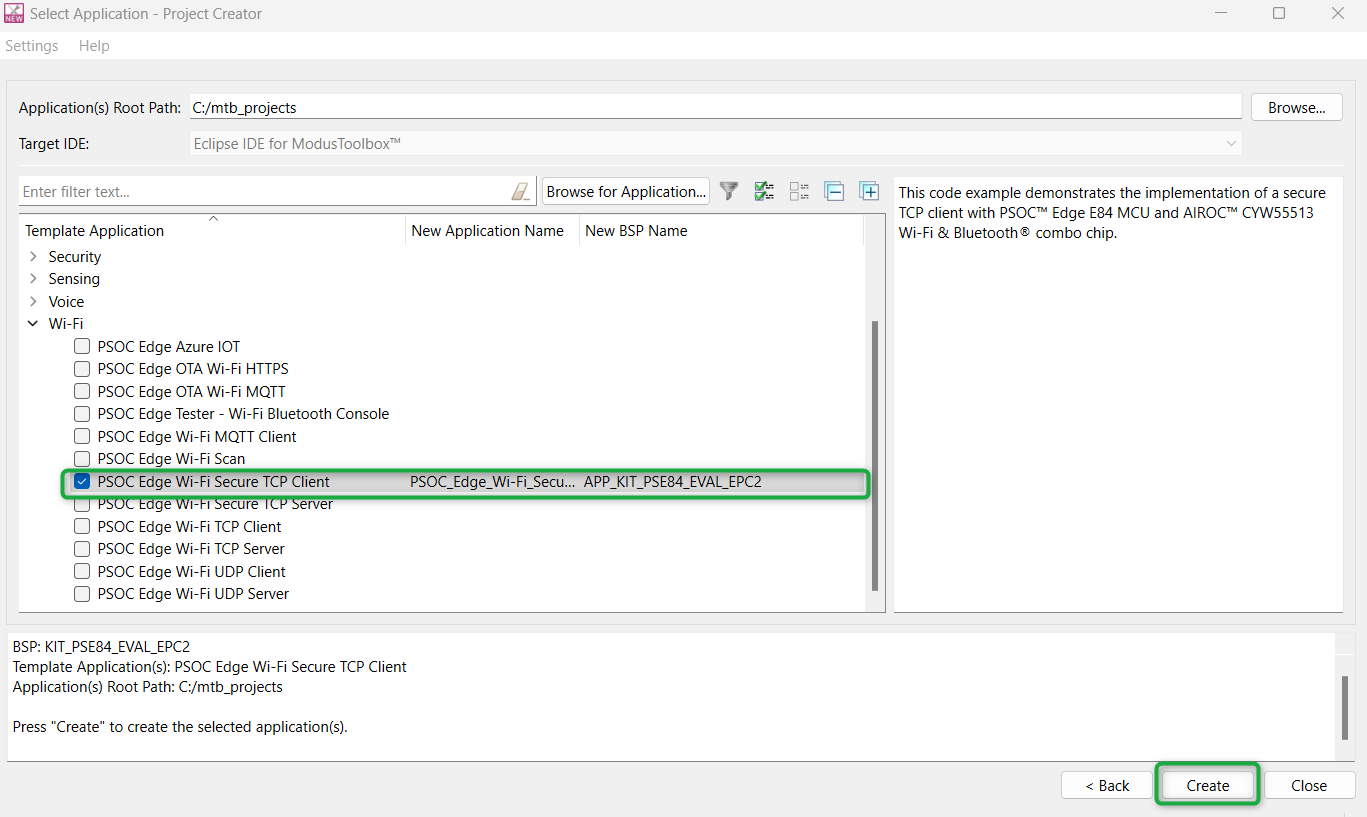
Figure 46
shows the
Select Application
window of the Project Creator tool. Select the
Wi-Fi Secure TCP Client
application under
Wi-Fi
, and optionally, in the
New Application Name
field, change the name of the application. Click
Create
and wait for the application to get downloaded and created in the workspace. Click
Close
to complete the application creation process.
Figure 46.
Create Wi-Fi Secure TCP Client code example
Select a starter application and create the application (applicable only for "Working from scratch" flow)
You can use an existing empty application as the starting point for the “Working from Scratch” development flow. This is a minimal starter application template for PSOC™ Edge MCU devices. This example uses FreeRTOS to blink two LEDs with different frequencies respectively from the Arm® Cortex®-M33 CPU and the Arm® Cortex®M55 CPU.
This code example has a three project structure (that is, CM33 secure, CM33 non-secure, and CM55 projects). All three projects are programmed to an external QSPI flash and executed in the XIP mode. Extended Boot launches the CM33 Secure project from a fixed location in an external flash, which then configures the protection settings and launches the CM33 non-secure application. Additionally, CM33 non-secure application enables the CM55 CPU and launches the CM55 application.
The application code of the Wi-Fi Secure TCP client uses only the CM33 CPU of the PSOC™ Edge E84 MCU. Thus, the application is written in the CM33 non-secure project (proj_cm33_ns) and the CM55 CPU (in proj_cm55) is subsequently put into Deep Sleep mode.
To create an Empty_app, in the
Select Application
window (see
Figure 47
), select
PSOC Edge Empty Application
. In the
Name
field, type in a name for the application if required and click
Next
; the application summary dialog appears. Click
Create
and wait for the application to get downloaded and created in the workspace. Click
Close
to complete the application creation process.
Figure 47.
Starter application window

Configure design resources
In this step, you will configure the design resources for your application. That is, you will be adding required middleware libraries and generating SSL certificate and private keys (not mandatory) required for the application.
Method | Actions |
|---|---|
“Using CE directly” (evaluate existing Code Example (CE) directly) | Read and understand all steps. The CE has the resource configurations done; therefore, you need not perform any of the steps in this section |
“Working from Scratch” (use existing Code Example (CE) as reference only) | Perform all steps |
Add libraries and middleware
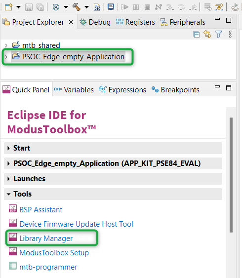
ModusToolbox™ provides a Library Manager tool to select various middleware components for developing Wi-Fi and other applications. To launch the Library Manager, select the empty application (the application name will vary based on the name you provided while creating the empty_app) and in the Quick Panel, click the
Library Manager
, as shown in
Figure 48
. Click on
Add Library
to add the required libraries and middleware for your application.
Figure 48.
Open Library Manager
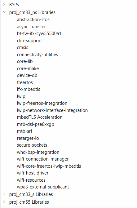
For Wi-Fi Secure TCP client design, follow these steps to add the required libraries:
Remove FreeRTOS from the CM33_NS project as shown in
Figure 49
as it will be added as part of wifi-core-freertos-lwip-mbedtls library, which will be added in the following steps
Figure 49.
Remove FreeRTOS
Add the
retarget-io
middleware to redirect standard input and output streams to the UART configured by the BSP. The initialization of the middleware will be done in the
main.c
file. After clicking on
Add Library
, select
proj_cm33_ns
the
target project
and
retarget-io
as the Peripheral (see
Figure 50
). You can also search the library name in the
Enter filter text
box provided
Figure 50.
Add retarget-io library

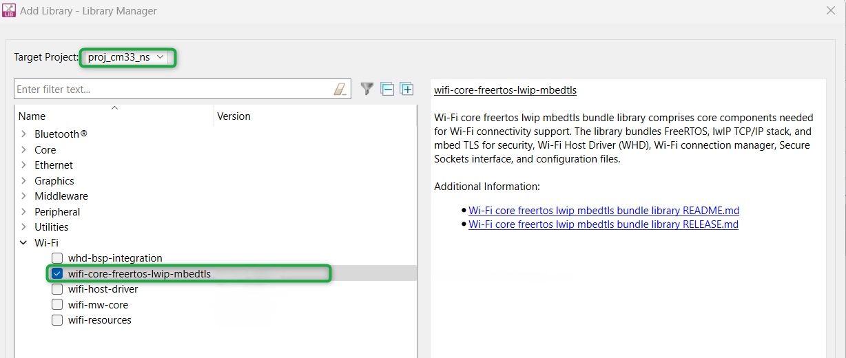
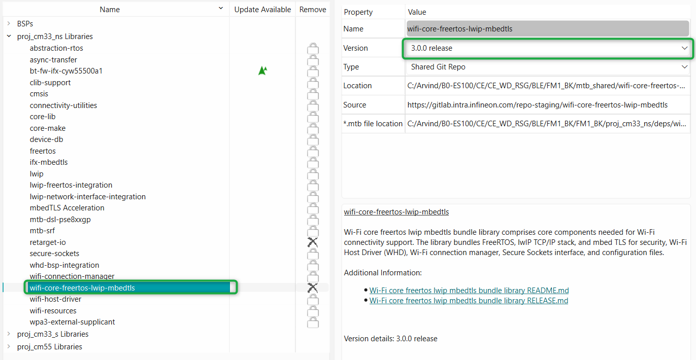
Add the
wifi-core-freertos-lwip-mbedtls
library. This bundle library comprises core components needed for Wi-Fi connectivity support. It bundles FreeRTOS, lwIP TCP/IP stack, and mbed TLS for security, Wi-Fi Host Driver (WHD), Wi-Fi Connection Manager (WCM), Secure Sockets interface, and configuration files.
Click on
Add Library
, select
proj_cm33_ns
as the
Target Project
and select
(see
Figure 51
)
Figure 51.
Add wifi-core-freertos-lwip-mbedtls library
All the required libraries are selected. To add them to the project, click
OK
and then
Update
shows the libraries selected and their dependency libraries. The files necessary to use the retarget-io and wifi-core-freertos-lwip-medtls are added in the
folders, and the
.mtb
files are added to the
deps
folder. Similarly, you can find other libraries under the respective folder in the
mtb_shared
folder
Figure 52.
Libraries for Wi-Fi Secure TCP client example
Change the library version by selecting the library and clicking on the library version, as shown in
Figure 53
Figure 53.
Change library version
Generate SSL certificate and private key (optional)
This section explains how to generate the self-signed SSL certificate and private key required for the implementation. It is not mandatory to generate an SSL certificate and private key as it is already present in the code example. You will be reusing the same while developing this design. However, you can still generate the certificate if you want to or if the certificate that is already present has expired.
The TCP client demonstrated in this design uses a self-signed SSL certificate. This requires OpenSSL that is already preloaded in the ModusToolbox™ software installation. Self-signed SSL certificate means that there is no third-party certificate issuing authority, commonly referred to as "CA" involved in the authentication of the client. Servers connecting to this client must have an exact copy of the SSL certificate to verify the client's identity.
Note:
An SSL certificate is a digital certificate that authenticates a website's identity and enables an encrypted connection. Secure Sockets Layer (SSL), a security protocol that creates an encrypted link between a web server and a web browser.
Follow these steps to generate a self-signed SSL certificate and private key:
Run the following command with a CLI (on Windows, use the command line "modus-shell" program provided in the ModusToolbox™ installation instead of a standard Windows command-line application) to generate the CA certificate using the following commands. Follow the instructions in the command window to provide the details required
openssl ecparam -name prime256v1 -genkey -noout -out root_ca.key
openssl req -new -x509 -sha256 -key root_ca.key -out root_ca.crt days -1000
Generate the client key pair and client certificate (signed using the CA certificate from Step 1). Follow the instructions in the command window to provide the details required
openssl ecparam -name prime256v1 -genkey -noout -out client.key
openssl req -new -sha256 -key client.key -out client.csr
openssl x509 -req -in client.csr -CA root_ca.crt -CAkey root_ca.key -CAcreateserial -out client.crt -days 1000 -sha256
Note:
You can also find these steps to generate a self-signed SSL certificate and private key in the README file under proj_cm33_ns folder of the wifi-secure-tcp-client code example.
Note:
The certificates will expire once the validity
period ends. The validity of these certificates is based on the number of days provided
in the command. You can change this by providing a different value in the
days -<number of days>
field in the
command.
After running the above commands, you will have a few generated files (that is, keys and certificates). Out of the generated files, you only require the following files:
client.crt (client's SSL certificate)
client.key (client's private key)
root_ca.crt (client's root SSL certificate)
The values in these certificate and keys should be provided into the network_credentials.h file of TCP client. Ensure you follow the same format (see the existing application file) while providing the certificate and key values into the
network_credentials.h
file. All these client’s (generated above) certificates and keys should match with the server’s certificate and key. Therefore, the
client.crt
and
client.key
should be renamed to
server.crt
and
server.key
and placed along with
root_ca.crt
inside the python-secure-tcp-server folder under
proj_cm33_ns
that contains the TCP server implementation.
The python scripts located inside the python-secure-tcp-server that contains a simple TCP server implementation will make use of these SSL certificates and a private key to make a handshake with the TCP client.
Write the application code
At this point in the development process, you have created an application and added the required libraries. This part examines the application code that implements the Secure TCP client functionality.
Method | Actions |
|---|---|
“Using CE directly” (evaluate existing code example (CE) directly) | Ignore Step 1 and Step 2. The CE already has all the necessary source files added. Read through the Firmware description section to understand the firmware design |
“Working from scratch” (use existing code example (CE) as reference only) | Perform Step 1 and Step 2. Also, read through the Firmware description section to understand the firmware design |
The application code must do the following significant tasks:
Perform system initialization followed by the initialization of UART (retarget_io), real-time clock (RTC), CLIB support library, and setup the LPTimer instance for CM33 CPU
Implement a task called tcp_secure_client_task, which does all the required functions such as initialization of SDIO instance and WCM, connection to Wi-Fi in either STA or AP addressing mode, initializing secure socket, initializing rootCA certificate, and creating TCP client identity for security and establishing a connection with the TCP server
Implement the callback functions to handle incoming messages from the server and to handle disconnection
Note:
The empty application of the PSOC™ Edge E8 MCU has a three project structure (proj_cm33_ns, proj_cm33_s, and proj_cm55). The application code of the Wi-Fi Secure TCP client example is to be written on the proj_cm33_ns project that uses the M33 core and subsequently the proj_cm55 project that uses the M55 core is put into Deep Sleep mode.
Step 1: Add files to your project (required only for the “Working from Scratch” flow).
Clone or download the Wi-Fi Secure TCP Client application code from the Infineon GitHub repository to a local repository
Copy and replace the following files/folders under proj_cm33_ns to your proj_cm33_ns folder of the "Empty_App" inside the ModusToolbox™ workspace folder
Source , which contains:
- main.c
- network_credentials.h
- secure_tcp_client.c
- secure_tcp_client.h
- retarget_io_init.c
- retarget_io_init.h
python-secure-tcp-server , which contains:
- tcp_secure_server.py
- root_ca.crt
- server.crt
- server.key
Note:The
root_ca.crt
,
server.crt
, and
server.key
files contain the SSL certificate and private key. You can use the same key that is provided in the application or you can generate your own key and SSL certificate by following the
Generate SSL certificate and private key (optional)
section. If you are generating your own key and certificate make sure that you provide the same in the
network_credentials.h
file of the TCP client application
Copy and replace the main.c file from the proj_cm55 folder of the same code example to your proj_cm55 folder of Empty_App inside the ModusToolbox™ workspace folder
Step 2: Add values to the variables in the
Makefile
of proj_cm33_ns of the Empty_app as shown below (required only for the "working from Scratch" flow).
COMPONENTS=FREERTOS LWIP MBEDTLS RTOS_AWARE
These components are required to include the files from FreeRTOS and to include lwIP and Mbed TLS libraries of the Wi-Fi stack
DEFINES+=MBEDTLS_USER_CONFIG_FILE='"mbedtls_user_config.h"'
DEFINES+=MBEDTLS_CONFIG_FILE='"mbedtls/mbedtls_config.h"'
DEFINES+=MBEDTLS_PSA_CRYPTO_CONFIG_FILE='"configs/ifx_psa_crypto_config.h"'
DEFINES+=CYBSP_WIFI_CAPABLE
DEFINES+=CY_RETARGET_IO_CONVERT_LF_TO_CRLF
DEFINES+=CY_RTOS_AWARE
MBEDTLS_USER_CONFIG_FILE='"mbedtls_user_config.h"' is defined to provide the user configuration to the Mbed TLS library
MBEDTLS_CONFIG_FILE='"mbedtls/mbedtls_config.h"' is defined to provide the default configuration of the Mbed TLS library
MBEDTLS_PSA_CRYPTO_CONFIG_FILE='"configs/ifx_psa_crypto_config.h"' is defined to provide the PSA configuration of Mbed TLS library
CYBSP_WIFI_CAPABLE is provided to enable the Wi-Fi functionality
CY_RTOS_AWARE is provided to inform the Peripheral Driver Library (PDL) that an RTOS environment is being used
CY_RETARGET_IO_CONVERT_LF_TO_CRLF is provided by the retarget-io library to enable conversion of the line feed (LF) into a carriage return followed by the line feed (CR and LF) on the output direction (STDOUT)
Firmware description
This section explains the application firmware of the Secure TCP client application. The important source files relevant to the user application-level code to this design are listed in
Table 9
.
Files | Description |
|---|---|
source/main.c | This file contains the function that is the entry point for execution of the user application code after device startup |
source/secure_tcp_client.c | This file contains tasks and functions related to secure TCP client operation |
source/secure_tcp_client.h | This file contains a declaration of tasks related to secure TCP client operation. |
source/retarget_io_init.c source/retarget_io_init.h | These files contain the initialization routine for the retarget-io middleware |
source/network_credentials.h | This file is the public interface for Wi-Fi/Soft-AP credentials and TLS credentials |
python-secure-tcp-server/root_ca.crt , python-secure-tcp-server/server.crt | These files are the root CA (self-signed) certificates for the server side. Doing execution, these files are compared with the certificates on the TCP client |
python-secure-tcp-server/server.key | This file contains the server’s private key. This key should match with the client’s private key to establish a TCP connection |
python-secure-tcp-server/tcp_secure_server.py | This file is the Python script that has to be run on the server side. This script contains a simple TCP server implementation |
FreeRTOSConfig.h | This file is provided by the FreeRTOS library and copied into the application directory. This file has settings for the FreeRTOS Kernel. The application can modify the settings based on the use case |
Makefile | This file contains settings for application build |
Note:
The python-secure-tcp-server folder contains files that are required for the secure TCP server. See the
Build, program, and test your design
section for details on how to run the Python script on the server.
User application code entry
The
main.c
file contains the
int main
()
function. This function is the entry point for executing the user application code after device initialization is complete. In this code example, this function does the following:
Initializes the BSP that includes initializing the target hardware. For example, it initializes system power management and device configuration. It performs other platform-specific initialization. If the BSP initialization fails, the app enters CY_ASSERT. If you are debugging your application, CY_ASSERT acts as a breakpoint
Initializes retarget-io to use the debug UART port to view the trace messages and prints a startup message on the debug UART using the
printffunctionInitializes real-time clock (RTC) and CLIB support library
Registers the SDHC System Power Management (SysPm) Callback
Initializes the tickless idle timer instance of the CM33 CPU. This lptimer instance is initialized and setup and an object is created and passed to the abstraction RTOS that implements the tickless idle mode. This is done to allow the device to enter into Deep Sleep when an idle task is executed
Enables the CM55 core. The RTOS task in the CM55 core is suspended which puts the CPU to Deep Sleep as only the CM33 core is used to run this application
A task named
tcp_secure_client_task
is created and the RTOS scheduler is started
The
secure_tcp_client.c
file contains the
tcp_secure_client_task()
function, callback events, and user interface logic. The
tcp_secure_client_task()
function does the following:
Configures and initializes the SDIO instance used in communication between the host MCU and the wireless device
Initializes the Wi-Fi Connection Manager (WCM) using the
cy_wcm_init()
function. This function initializes the WCM resources, WHD, Wi-Fi transport, turns Wi-Fi on; and starts up the network stack
Connects to Wi-Fi AP using the user-configured credentials WIFI_SSID and WIFI_PASSWORD in case of STA interface mode and configures the device in AP mode and initializes a SoftAP with the given credentials SOFTAP_SSID, SOFTAP_PASSWORD, and SOFTAP_SECURITY_TYPE in case of Soft AP interface mode. This Wi-Fi connection is made using either the IPv4 address or the IPv6 address
Note:
Wi-Fi credentials for STA and SoftAP modes are provided in the
network_credentials.h
file. Additionally, the Wi-Fi Connection mode (STA or SoftAP) and IP address (v4 or v6) are selected through the USE_AP_INTERFACE and USE_IPV6_ADDRESS macros in the
network_credentials.h
file
A binary semaphore is created to keep track of the TCP server connection
Initializes secure socket library using
cy_socket_init()
function
Initializes the global trusted RootCA certificates used for verifying certificates received during TLS handshake by calling the
cy_tls_load_global_root_ca_certificates()
function. This function parses the RootCA certificate chain and converts it to the underlying TLS stack format. It also stores the converted RootCA in its internal memory. This function overrides previously loaded RootCA certificates
Creates TCP client identity using the SSL certificate and private key
In for () loop,
Reads IPV4/IPV6 address of the TCP server from UART terminal
Establishes connection to the secure TCP server by creating a secure TCP client socket and connecting a TCP/TLS socket to the specified server IP address and port
A secure TCP client socket is created using the
connect_to_secure_tcp_server()
function and it does the following:
Creates a new secure TCP socket
sets the socket options to use TLS identity
Sets a callback function to handle incoming messages from the server and to handle disconnection
Callback events
Two callback functions
tcp_client_recv_handler()
and
tcp_disconnection_handler()
are implemented to handle the callback events such as command from the server and disconnection of TCP.
The
tcp_client_recv_handler()
callback function is implemented to handle incoming TCP server messages. In this function, the command (‘0’ or ‘1’) is received from the TCP server using the
cy_socket_recv()
API and the LED is turned ON or OFF based on the received command
The
tcp_disconnection_handler()
callback function handles the TCP client disconnection event
Build, program, and test your design
This section shows how to build, program, and test the Wi-Fi Secure TCP client application on the PSOC™ Edge E84 Evaluation Kit. It also explains how to run the Python script on the server side (your PC in this case).
At this point, it is assumed that you have followed the previous steps in this application note to develop the Wi-Fi Secure TCP client application.
Method | Actions |
|---|---|
“Using CE directly” (evaluate existing Code Example (CE) directly) | Perform all the steps in this section |
“Working from Scratch” (use existing Code Example (CE) as reference only) | Perform all the steps in this section |
Note:
To understand the build and program process of a simpler application, see the Getting started with PSOC™ Edge E8 MCU application note that explains how to run a simple hello world application on the KIT_PSE84_EVAL_EPC2/KIT_PSE84_EVAL_EPC4.
To build, program, and test the application, do the following:
Connect the kit to your PC using the provided USB cable
The USB – UART serial interface on the kit provides access to the UART interface of the PSOC™ Edge E84 device. Use your favorite serial terminal application (
Tera Term
is used in this design) and connect to the USB – UART serial port. Configure the terminal application to access the serial port using the following settings:
Baud rate: 115200 bps; Data: 8 bits; Parity: None; Stop: 1 bit; Flow control – None; New line for receiving data: Line Feed (LF) or auto setting
The kit can be configured to run either in the Wi-Fi STA interface mode or in the AP interface mode. The interface mode is configured using the
USE_AP_INTERFACE
macro defined in the
network_credentials.h
file. Based on the desired interface mode, do the following:
Kit in STA mode (default interface):
Set the
USE_AP_INTERFACE
macro to '0', which is the default mode
Modify the
WIFI_SSID
,
WIFI_PASSWORD
, and
WIFI_SECURITY_TYPE
macros to match with the Wi-Fi network credentials that you want to connect to. These macros are defined in the
network_credentials.h
file. Ensure that the Wi-Fi network that you are connecting to is configured as a private network for the proper functioning of this example
Kit in AP mode:
Set the
USE_AP_INTERFACE
macro to '1'
Update
SOFTAP_SSID
,
SOFTAP_PASSWORD
, and
SOFTAP_SECURITY_TYPE
macros as desired, which is an optional step
Configure the IP addressing mode. By default, IPv4-based addressing is used. To use IPv6 addressing mode, set the
USE_IPV6_ADDRESS
macro defined in the
secure_tcp_server.h
file as follows:
#define USE_IPV6_ADDRESS (1)
Build and Program the Application: In the Project Explorer, select the
<App name> project
. In the Quick Panel, scroll to the
Launches
section, and click the
<App name> Program (KitProg3_MiniProg4)
configuration as shown in
Figure 54
Figure 54.
Build and program application

Note:
You can also use the command-line interface (CLI) to build and program the application. See the Build system chapter in the
ModusToolbox™ tools package user guide
. This document is located in the
/docs_<version>/
folder in the ModusToolbox™ installation directory
After programming, the application starts automatically. Confirm that the text as shown in either one of the following figures is displayed on the UART terminal. Note that the Wi-Fi SSID and the IP address assigned will be different based on the network that you have connected to. In AP mode, the AP credentials will be different based on your configuration in Step 3
Figure 55.
Wi-Fi connection status (IPv4 address and STA mode)
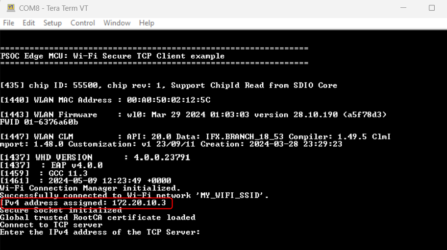
Figure 56.
Wi-Fi connection status (IPv6 address and STA mode)
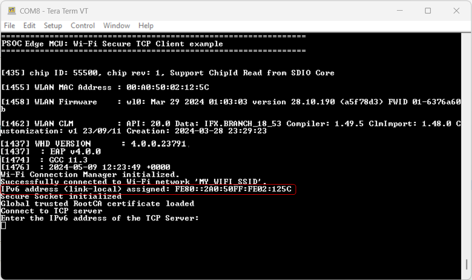
Figure 57.
Wi-Fi connection status (IPv4 address and AP mode)
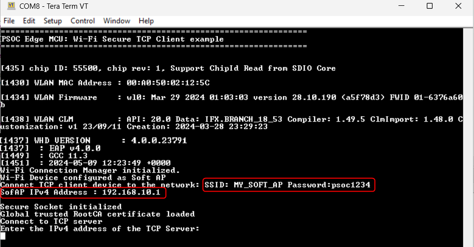
Similarly, when the application is configured for IPv6 and AP mode, the IPv4 address displayed in
Figure 57
will be replaced by the IPv6 address
Connect your PC to the Wi-Fi AP that you have configured in Step 3
In STA mode:
Connect the PC to the same AP to which the kit is connected
In AP mode:
Connect the PC to the kit's AP
Determine the PC's IP address
To determine the IP address, type the following command in the command shell based on your operating system
Windows:
ipconfig
Linux:
curl ifconfig.me
macOS:
ifconfig | grep inet
Open a command shell from the project directory and run the Python TCP secure server (
(project directory)\python-secure-tcp-server
). In the command shell opened in the project directory, type the following command based on the IP address mode configuration:
For IPv4-based addressing:
python tcp_secure_server.py
For link-local IPv6 based addressing:
python tcp_secure_server.py ipv6
Note:
Ensure that the firewall settings of your PC allow access to the Python software so as to allow communication with the TCP client. See this
community thread
In the terminal program, enter the IP address determined in Step 8
From the Python secure TCP server, send the command to turn the LED ON or OFF to the TCP client ('0' to turn the LED OFF and '1' to turn the LED ON). Observe the user LED (CYBSP_USER_LED1) turning ON/OFF on the board
Figure 58.
LED status on TCP server (IPv4 addressing mode) - using python script
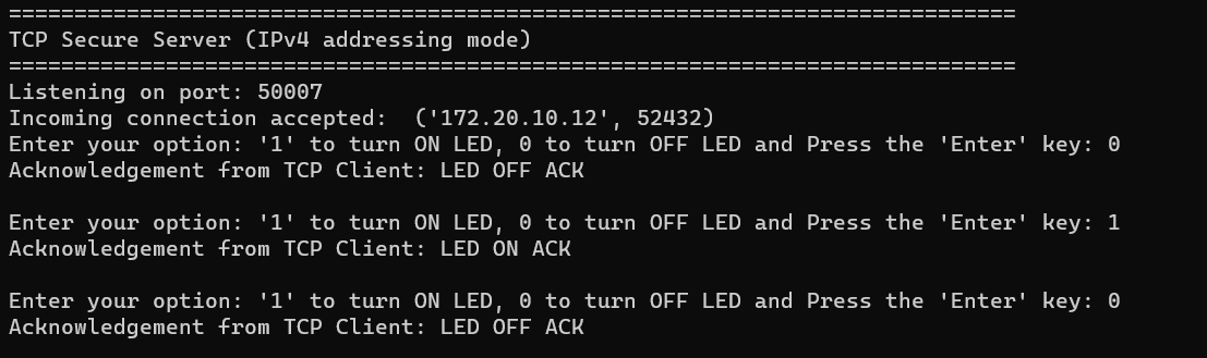
Figure 59.
LED status on TCP client (IPV4 addressing and STA mode)
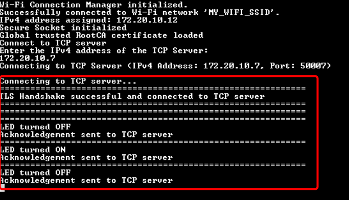
Figure 60.
LED status on TCP client (IPV4 addressing and AP mode)
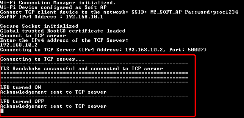
Figure 61.
LED status on TCP server (IPV6 addressing mode) - using python script
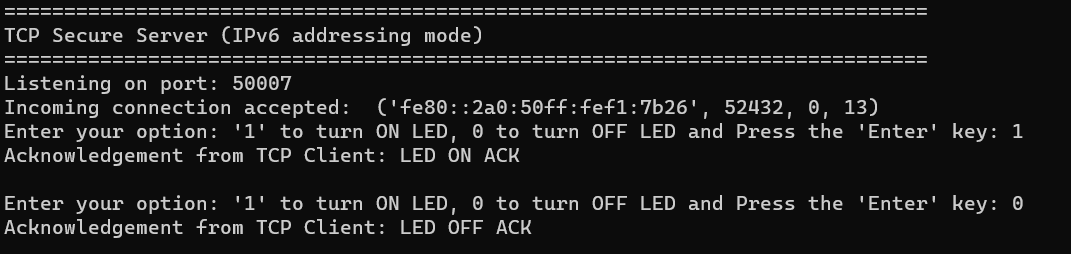
Figure 62.
LED status on TCP client (IPV6 addressing and STA mode)
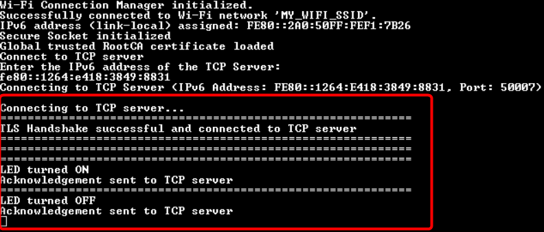
When the CE is configured in AP and IPv6 mode, the only change from
Figure 60
is the IPv6 address that is being displayed instead of IPv4
You have successfully developed and tested a simple Wi-Fi application for the PSOC™ Edge E84 device using Eclipse IDE for ModusToolbox™.
Summary
The application note introduced the connectivity portfolio offered by Infineon Technologies. It also explained the module partners and connectivity solution provided by ModusToolbox™. It provided the step-by-step demonstration on how to build a simple Bluetooth® LE and Wi-Fi application and to test it on the PSOC™ Edge E8 MCU.
A wealth of code examples, application notes, and other technical documents are available to help you quickly develop
PSOC™
6 or Edge E8 based Bluetooth® and Wi-Fi applications that meet your end application requirements. See the
References
section to continue learning more about the
PSOC™
device and to develop Bluetooth® and Wi-Fi applications.
References
Application notes
Infineon Technologies AG:
AN228571 – Getting started with PSOC™ 6 MCU on ModusToolbox™ software
;
Available online
Infineon Technologies AG:
AN235935 – Getting started with PSOC™ Edge E8 MCU on ModusToolbox™ software
;
Available online
Infineon Technologies AG:
AN237038 – Getting started with PSOC™ 63 MCU Bluetooth® LE on ModusToolbox™
;
Available online
Infineon Technologies AG:
AN235691 – ModusToolbox™ and Friends
;
Available online
Webpages
Infineon Technologies AG:
PSOC™ 6 MCU
;
Available online
Infineon Technologies AG:
ModusToolbox™ software
;
Available online
Infineon Technologies AG:
ModusToolbox™ for connectivity
;
Available online
Infineon Technologies AG:
ModusToolbox™ GitHub page
;
Available online
Infineon Technologies AG:
AIROC™ CYW55513 Wi-Fi and Bluetooth® LE chip
;
Available online
Infineon Technologies AG:
AIROC™ Wi-Fi + Bluetooth® Combo Chips
;
Available online
Code examples
Infineon Technologies AG:
PSOC™ Edge MCU: Bluetooth® LE Find Me;
Available online
Infineon Technologies AG:
PSOC™ Edge MCU: Wi-Fi Secure TCP Server;
Available online
Infineon Technologies AG:
PSOC™ Edge MCU: Wi-Fi Secure TCP Client;
Available online
Revision history
Document revision | Date | Description of changes |
|---|---|---|
*D | 2025-09-05 | Release to web |
Trademarks
The Bluetooth® word mark and logos are registered trademarks owned by Bluetooth SIG, Inc., and any use of such marks by Infineon is under license.
PSOC™, formerly known as PSoC™, is a trademark of Infineon Technologies. Any references to PSoC™ in this document or others shall be deemed to refer to PSOC™.