AN241681 Low-power system design with PSOC™ Edge MCU and AIROC™ Wi-Fi & Bluetooth® combo chip
About this document
Scope and purpose
This application note describes how to use the PSOC™ Edge MCU and AIROC™ Wi-Fi & Bluetooth® combo chip to design a low-power connectivity solution for Internet of Things (IoT) applications. The technical description in this application note applies to other applications based on PSOC™ Edge MCU and AIROC™ Wi-Fi & Bluetooth® combo chip.
This application note provides an overview of low-power modes and features in the AIROC™ CYW55513 Wi-Fi & Bluetooth® combo chip. It also describes various techniques, such as host offload features to optimize power consumption in the connectivity system, and assist with the Low-Power Assistant (LPA) tool.
Intended audience
This document is intended for anyone using the AIROC™ Wi-Fi & Bluetooth® combo chip and PSOC™ Edge MCU to design a low-power connectivity solution for IoT applications.
Introduction
The PSOC™ Edge E84 MCU is a programmable embedded system-on-chip (SoC) with dual CPUs, integrating Arm® Cortex®-M33 and Arm® Cortex®-M55. It features a range of capabilities, including a neural network (NN) coprocessor, and incorporate functional blocks to support graphics, audio, and digital signal processor (DSP) capabilities. This MCU is designed for ultra-low-power applications, particularly in wearables and Internet of Things (IoT) products.
The AIROC™ CYW55513 Wi-Fi & Bluetooth® combo chip device runs the lower levels of the connectivity stack in hosted mode while a host processor such as PSOC™ Edge E84 MCU runs the upper levels of the connectivity stack and the application. This solution supports Bluetooth® and Wi-Fi. The communication between the host MCU and the AIROC™ device happens via UART in case of Bluetooth® LE and Secure-Digital-Input-Output (SDIO) in case of Wi-Fi.
AIROC™ CYW55513 is a low-power, single-chip device that supports single-stream, tri-band Wi-Fi 6/6E, IEEE 802.11ax-compliant Wi-Fi MAC/baseband/radio, and Bluetooth®/Bluetooth®Low Energy 5.3. In 802.11ax mode, the device supports rates up to 1024 QAM MCS11 in 20 MHz channels. All legacy rates in the 802.11a/b/g/n/ac are also supported. Included on-chip are 2.4 GHz, 5-7 GHz transmit power amplifiers (PA), and low-noise amplifiers (LNA). The device can operate with an external power amplifiers and low-noise amplifiers, and antenna diversity, if improved range is required. An SDIO v3.0 interface or Generic Serial Peripheral Interface (GSPI) are available for interfacing with the host.
AIROC™ CYW55513 includes a Bluetooth® subsystem that is Bluetooth® 5.3-compliant, supporting Basic Rate, Enhanced Data Rate (EDR), and Bluetooth® Low Energy. The device supports Bluetooth® Low Energy 2 Mbps, Bluetooth® Low Energy 1 Mbps, Low Energy Mesh, Low Energy Long Range (LR), and advertising extensions.
The device can support Bluetooth® Low Energy audio, with Low Complexity Communication (LC3) codec running on the device, enabling typical smart watch audio use cases. A pair of time-division multiplexing (TDM) interfaces enables a flexible interface for various audio use cases and a pulse-density modulation (PDM) interface is available for connecting digital microphones. The device includes on-chip power amplifiers supporting three different output power paths optimized for best efficiency, 0 dBm, +13 dBm, and +19 dBm path for driving poor antennas in wearable devices. The device also features a flexible Bluetooth® receiver offering a dedicated Bluetooth® LNA (dLNA) path or a Bluetooth® receive path that can be shared (sLNA) with the 2.4 GHz WLAN receive path. A 4-wire UART or SDIO (shared with Wi-Fi) interface is available for interfacing with the host processor.
AIROC™ CYW55513 is designed to address the needs of Internet on Things (IoT) devices that require minimal power consumption and compact size. AIROC™ CYW55513 includes advance coexistence hardware mechanisms and algorithms which ensure that simultaneous WLAN and Bluetooth® operation is optimized for maximum performance.
This application note requires a basic knowledge of the AIROC™ CYW55xxx Wi-Fi & Bluetooth® combo chip and PSOC™ Edge MCU architecture, and the ability to develop applications using ModusToolbox™ software.
Low-power overview
AIROC™ CYW55513 Wi-Fi & Bluetooth® combo chip power modes
AIROC™ CYW55513 Wi-Fi & Bluetooth® combo chip has been designed with the stringent power consumption requirements of battery-powered IoT devices in mind.
Table 1
lists the power mode supported in AIROC™ CYW55513 device.
Power mode | Description |
|---|---|
Active |
|
Sleep (station doze state) |
|
power Down (Off) |
|
AIROC™ CYW55513 Wi-Fi & Bluetooth® combo chip includes an advanced WLAN power management unit (PMU) sequencer, which provides significant power savings. It puts the AIROC™ CYW55513 Wi-Fi & Bluetooth® combo chip device into various power management states appropriate to the current environment and activities performed.
The PMU enables and disables internal regulators, switches, and other blocks based on the computation of the required resources and a power management state transition table that describes the relationship between resources and the time needed to enable and disable them. Configurable, free-running counters (running at 32.768 kHz LPO clock) in the PMU sequencer are used to turn ON/turn OFF individual regulators and power switches. Clock speeds are dynamically changed (or gated altogether) for the current mode. Slower clock speeds are used wherever possible. See the
AIROC™ Wi-Fi & Bluetooth® combo chip
for details on the PMU.
PSOC™ Edge E84 MCU power modes
The PSOC™ Edge MCU can operate in three CPU power modes and five system modes as described in
PSOC™ Edge E84 MCU power modes
. These modes are intended to minimize the average power consumption in an application. See the AN237976 – PSOC™ Edge MCU low-power modes and power reduction techniques application note
2
.
Table 2
summarizes PSOC™ Edge MCU power modes and provides a simplified version for representing power mode transitions in a design with PSOC™ Edge MCU and AIROC™ Wi-Fi & Bluetooth® combo chip.
Power mode | Description |
|---|---|
CPU Active Power modes | |
System High Performance (HP) |
|
System Low Power (LP) |
|
System Ultra-Low Power (ULP) |
|
System Power Modes | |
CPU Active |
|
CPU Sleep |
|
CPU Deep Sleep |
|
System Deep Sleep 1 |
|
System Hibernate |
|
AIROC™ CYW55513 Wi-Fi & Bluetooth® combo chip power-related hardware signals
AIROC™ CYW55513 Wi-Fi & Bluetooth® combo chip has six hardware signals that provide the power control interface to the host (PSOC™ Edge MCU)
Signal | Description |
|---|---|
| This signal is used by the PMU (with BT_REG_ON) to power up the WLAN section. It is OR-gated with the BT_REG_ON input to control internal AIROC™ CYW55513 Wi-Fi & Bluetooth® combo chip regulators. When this pin is HIGH , the regulators are enabled, and the WLAN section is out of reset. When this pin is LOW , the WLAN section is in reset. If BT_REG_ON and WL_REG_ON are both LOW , the regulators are disabled |
| This signal is used by the PMU (with WL_REG_ON) to decide whether to power down internal AIROC™ CYW55513 Wi-Fi & Bluetooth® combo chip regulators. When this pin is HIGH , the regulators are enabled, and the Bluetooth® section is out of reset. When this pin is LOW , the Bluetooth® section is in reset. If BT_REG_ON and WL_REG_ON are LOW , the regulators will be disabled |
| Bluetooth® device wake-up: Signal from the host (PSOC™ Edge MCU) to AIROC™ CYW55513 Wi-Fi & Bluetooth® combo chip indicating that the host requires attention like sending data to the Bluetooth® controller
The polarity of this signal is software-configurable and can be asserted as HIGH or LOW . Default is asserted HIGH |
| Host wake-up signal from the AIROC™ CYW55513 Wi-Fi & Bluetooth® combo chip. Bluetooth® controller to the host indicating that the AIROC™ CYW55513 Wi-Fi & Bluetooth® combo chip Bluetooth® controller has data for the host
The polarity of this signal is software-configurable and can be asserted as HIGH or LOW . Default is asserted HIGH |
| Host wake-up signal from the AIROC™ CYW55513 Wi-Fi & Bluetooth® combo chip WLAN device to the host indicating that the AIROC™ CYW55513 Wi-Fi & Bluetooth® combo chip WLAN device has data for the host to process. This signal is an active HIGH signal
|
| WLAN device wake-up signal. This signal is not used in current designs and SDIO-based wake-up is used to wake up the WLAN device |
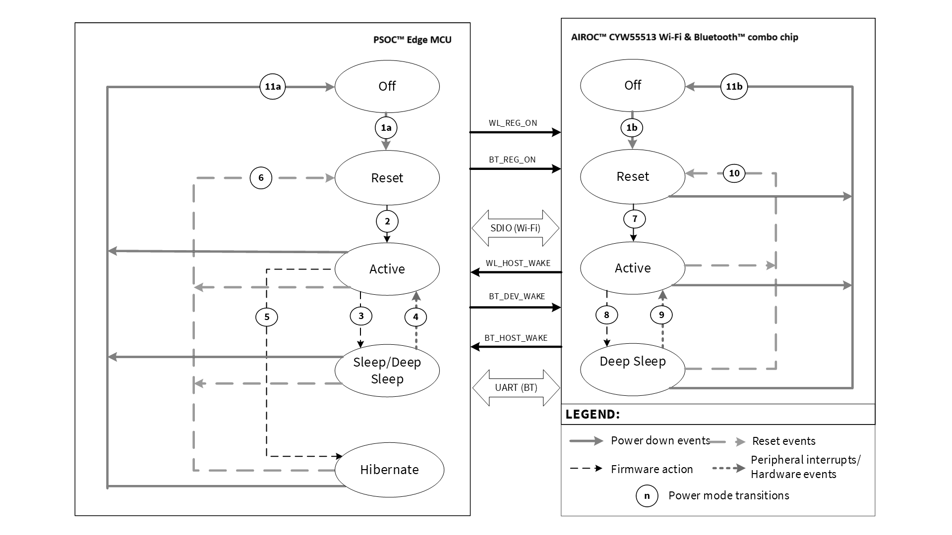
Power mode transition of host MCU PSOC™ Edge and AIROC™ CYW55513
Transition | Description | Trigger |
|---|---|---|
1a | PSOC™ OFF to reset transition | Power supply applied to PSOC™ Edge MCU |
1b | AIROC™ CYW55513 Wi-Fi & Bluetooth® combo chip OFF to reset transition | Power supply applied to AIROC™ CYW55513 Wi-Fi & Bluetooth® combo chip |
2 | PSOC™ reset to Active transition | Firmware (boot/startup) transitions from reset to Active mode |
3 | PSOC™ Active to Sleep or Deep Sleep transition | Firmware (OS idle task) transitions from active to Sleep or Deep Sleep mode |
4 | PSOC™ Sleep or Deep Sleep to active transition | Wake-up (interrupt) from Sleep/Deep Sleep; typical sources in an AIROC™ CYW55513 Wi-Fi & Bluetooth® combo chip design:
|
5 | PSOC™ active to Hibernate transition | Firmware (enter hibernate) transitions from active to Hibernate mode |
6 | PSOC™ transitions to reset state | Any reset event including hibernate wake-up, external reset, and so on. |
7 | AIROC™ CYW55513 Wi-Fi & Bluetooth® combo chip reset to active transition | External events transition AIROC™ CYW55513 Wi-Fi & Bluetooth® combo chip out of reset; either BT_REG_ON or WL_REG_ON pulled HIGH by PSOC™ Edge MCU. |
8 | AIROC™ CYW55513 Wi-Fi & Bluetooth® combo chip active to Deep Sleep transition | AIROC™ CYW55513 Wi-Fi & Bluetooth® combo chip enters DS0 mode; managed by on-chip PMU and requires enabling power save in the device |
9 | AIROC™ CYW55513 Wi-Fi & Bluetooth® combo chip Deep Sleep to active transition | External events or PMU transitions AIROC™ CYW55513 Wi-Fi & Bluetooth® combo chip to active mode; possible PSOC™ Edge MCU actions:
|
10 | AIROC™ CYW55513 Wi-Fi & Bluetooth® combo chip transitions to reset state | External events transition AIROC™ CYW55513 Wi-Fi & Bluetooth® combo chip to reset state; both WL_REG_ON and BT_REG_ON are pulled LOW by PSOC™ Edge MCU |
11a | PSOC™ transitions to OFF state | Power supply removed from PSOC™ Edge MCU (Power Down) |
11b | AIROC™ CYW55513 Wi-Fi & Bluetooth® combo chip transitions to OFF state | Power supply removed from AIROC™ CYW55513 Wi-Fi & Bluetooth® combo chip (Power Down) |
WLAN power optimization techniques
IEEE 802.11 (Wi-Fi) power saving
Topics in this section are partly based on information contained in the IEEE
802.11 specification document
. The 802.11 standard includes several parameters that allow stations to save power, although power saving is accomplished at the expense of throughput or latency to the station.
This section only provides an overview of power-saving methods and associated terms from the IEEE specification. If you are already familiar with the topic and interested in the implementation, see
Wi-Fi power save implementation
.
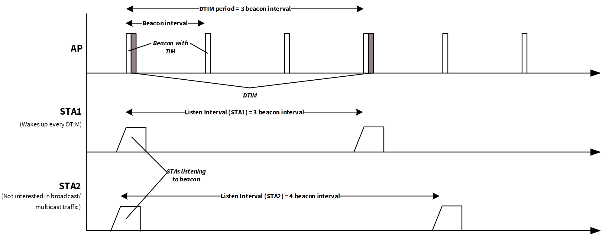
Beacon interval
Beacon frames are periodic frames broadcast by the Wi-Fi access points (APs) to communicate throughout the serviced area the characteristics of the connection offered to the Wi-Fi stations (STAs). This information is used by STAs trying to connect to the network as well as STAs already associated with the Basic Service Set (BSS). The period at which beacon frames are transmitted is called “Target Beacon Transmission Time” (TBTT) or simply “Beacon Interval”. Even though the beacon interval is configurable for a given AP, it is typically set to 102.4 ms (100-time units, where the 1-time unit is 1024 µs as per 802.11 specifications). The beacon interval information is available as part of the beacon frame itself. See the
802.11 specification
for details. In addition, each beacon includes a Traffic Indication Map (TIM) that contains information regarding packets buffered for STAs. It is the responsibility of the STAs to read the TIM and retrieve the packets destined for them.
Listen interval
To save power, STAs sleep by powering down most of the Wi-Fi subsystem. While the STAs are asleep, APs buffer frames for them and indicate the availability through beacon TIMs. The sleeping STAs periodically wake up to listen to traffic announcements (TIMs) and determine whether the AP has any buffered frames. When STAs associate with an AP, part of the data in the Association Request frame is the listen interval. The listen interval indicates to the AP the frequency at which a power save station will wake up to listen to beacon frames. An AP may use the listen interval as a guide to determine the duration it should retain buffered frames for a power save station. Larger listen intervals require more AP memory for frame buffering.
APs generally do not consider the listen interval requested by an STA. If an STA sets the listen interval to a value, there is no guarantee that the AP buffers all the packets received for the station while the station is asleep. In addition, if the AP supports Delivery Traffic Indication Map (DTIM), that setting may override the listen interval requested by STAs.
Most APs enforce an association timeout on stations, that is, if the AP has not received a frame from a station within the association timeout (usually 60 seconds) or the station has not returned an ACK to a keep-alive frame, the station is disassociated. The association timeout cannot be negotiated by the station.
DTIM period
The DTIM period is a parameter associated with an infrastructure network and is advertised in the AP Beacon frame. The polled approach using standard TIMs is not suitable for multicast and broadcast frames, because it takes too much capacity to transmit multicast and broadcast frames multiple times. Instead of the polled approach, broadcast and multicast frames are delivered after every DTIM interval.
Increasing the DTIM allows stations to conserve power more effectively at the cost of buffer space in the AP. It also delays the reception of multicast and broadcast frames by all stations, including stations in active mode.
Note that the listen interval is recommended to be equal to (or less than) the DTIM period for the STA to receive all unicast, multicast, and broadcast packets. This ensures an optimal power and latency tradeoff.
Usually, the DTIM period is set as the number of beacon intervals in the AP. The default DTIM period for most APs are either DTIM=1 (DTIM every beacon), DTIM=3 (DTIM every third beacon), or DTIM=10. In the case of DTIM=3, the station needs to only wake from low-power mode to receive every third beacon and any ensuing queued broadcast or multicast traffic.
explains the beacon interval, listen interval, and DTIM period in an infrastructure network.
Figure 2.
802.11 infrastructure network operation
Power-saving methods
Although the 802.11 transmitted power consumption is at least five times higher than the received power consumption, even for medium transmit-duty-cycle applications, much of the energy in a battery-powered Wi-Fi station is consumed by the receiver. Unless power save techniques are used, the 802.11 receiver may be powered ON for significant periods of time while the station waits for network clients to respond to requests. It does not take very long for a 130-mW receiver power consumption to discharge a battery.
Wi-Fi STAs use different mechanisms to save power. STAs with low duty cycle and long battery life requirements, Wi-Fi sensors, for example, may use the standard 802.11 Power Save Poll (PS-Poll) mechanism. STAs requiring higher throughput, wireless speakers, for example, consider using a non-standard 802.11 power save mechanism. These methods are described in this section.
Note:
STAs requiring a more fine-grained power save mechanism to differentiate power save for various traffic priorities may consider using unscheduled automatic power save delivery (U-APSD) or Wi-Fi multimedia (WMM) power save. AIROC™ CYW55513 Wi-Fi & Bluetooth® combo chip currently does not support WMM power save.
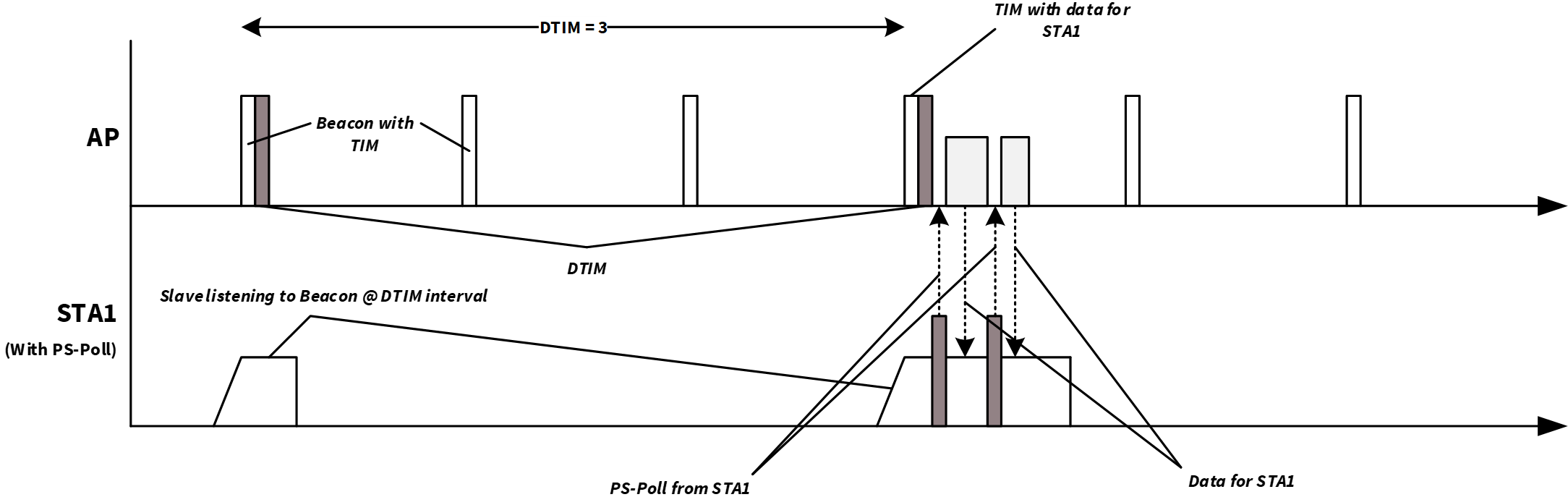
Power Save-Poll (PS-Poll)
Power Save-Poll suits for STAs that primarily transmit data to the Wi-Fi network at low-duty cycles. The PS-poll mechanism works as follows:
STA sends a frame to the AP with the Power Management bit set and then goes to Sleep mode
AP notes that the STA has gone to Sleep mode and buffers frames for the STA
STA wakes up periodically to check the AP beacon frame for an indication of buffered frames. The wake period depends on the configured listen interval and whether the STA is configured to receive group-addressed frames from a beacon containing a DTIM
If the AP indicates that it has buffered frames addressed to the STA, the STA sends a PS-Poll frame to the AP
The AP sends a frame to the STA and sets the ‘More Data’ bit if additional frames are buffered
The STA might send another PS-Poll frame to retrieve additional buffered frames (if the More Data bit is set) or return to Sleep mode
When the STA needs to transmit data, it can wake up and transmit data anytime without waiting for the beacon interval as the AP is active all the time
Figure 3.
Power Save-Poll
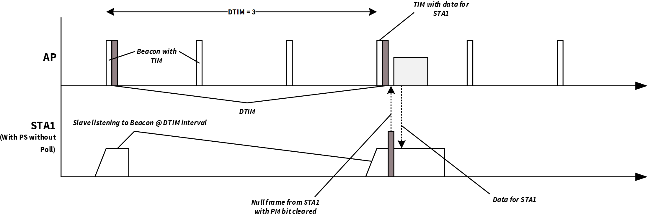
802.11 Power Save without Poll (PS-non-Poll)
A non-standard mechanism known broadly as 802.11 power save without poll (PS-non-poll) enables STAs to use 802.11 power saving based on a ‘trigger’ frame as follows:
STA sends a frame to the AP with the ‘Power Management’ bit set and then goes to Sleep mode
AP notes that the STA has gone to Sleep and buffers frames for the STA
STA wakes up periodically. The STA may (or may not) first check the AP beacon frame for an indication of buffered frames before sending any frames to the AP
The STA sends a Null Function data frame, or a data frame if available, to the AP with the Power Management bit is cleared
The AP notes that the STA is awake and sends buffered frames
STA receives the frames, waits for a timeout period to receive additional frames (if available), and then returns to sleep as described in Step
1
Figure 4.
Power Save without Poll
Association timeout limit
If an STA does not expect to receive directed frames from the AP asynchronously, and it is not interested in receiving broadcast or multicast traffic, then further power savings may be achieved.
Because APs generally have an association timeout limit with a default value of 60 seconds, an STA that uses power save must wake up before the association timeout expires and send or receive a directly addressed frame to inform the AP that the STA is still associated. Failure to comply results in the AP de-authenticating the STA. Some APs allow the association timeout limit to be set to a value higher than 60 seconds, but the higher limit is not signaled to the station and must be manually configured.
802.11ac-friendly features
AIROC™ CYW55513 Wi-Fi & Bluetooth® combo chip provides 802.11ac friendliness by supporting 1024-QAM (for 20-MHz channels in the 5-GHz band) enabling data rates of up to 78 Mbps with 802.11ac APs. This enables superior throughput and reduced power consumption in the device by sending/receiving data and then going back to sleep faster. In addition, it supports 802.11ac's ‘explicit beamforming’ feature to offer significantly higher throughputs than 802.11n chipsets at any given range.
Wi-Fi power save implementation
Wi-Fi Host Driver (WHD) power save interface
The power save implementation is provided as part of the
WHD library
. In addition, platforms such as FreeRTOS implement their power save mechanisms on top of the WHD to provide seamless low-power integration.
Table 5
describes the low-level functions available as part of WHD providing various power-save features. See the
WHD API reference guide
for details.
WHD API | Description |
|---|---|
| Enables PS-poll mode in the device ( Power Save-Poll (PS-Poll) ) |
| Enables 802.11 PS-non-poll mode in the device (see 802.11 Power Save without Poll (PS-non-Poll) ). Use this mode when it is important to maintain throughput |
| Disables power save mode in the device; by default, power save is enabled in the WLAN device. |
WHD Power save APIs | Sets the number of beacons to be skipped while the Wi-Fi chip is sleeping. Only works when Wi-Fi power save is enabled and the DTIM interval broadcasted by the AP is zero (that is, no DTIM in the network) |
| Gets the current value of all beacon listen interval variables |
Note that power save with throughput is enabled in the WLAN device by default. The enable/disable power save APIs can be called to change or disable the power save option in the WLAN. The WLAN automatically manages the entry and exit of DS0 after the power save is enabled. The PSOC™ Edge MCU: WLAN low power code example
1
demonstrates the use of WHD power save APIs. To achieve good Wi-Fi throughput, refer to the
Wi-Fi Bluetooth® tester
application, which provides a technical framework for optimizing Wi-Fi performance.
Cyclic timers in network stack
Platforms that implement network stacks, such as lightweight TCP/IP stack (lwIP), run periodic timers for various network-related activities. These timers are used as ticks for network activity such as Address Resolution Protocol (ARP) cache table expiry and Dynamic Host Configuration Protocol (DHCP) lease renewal timeouts. The period of these timers can vary from 100 ms to 60 s. The host waking up periodically to service these timers is required for proper functioning. However, if the application wants to suspend these timers when it does not anticipate any network timeout activity and for a longer stay in low-power modes, there is an option to suspend and resume the network stack.
This feature is provided as part of the low-power assistant middleware helper files. The
wait_net_suspend()
API, available in the
lpa/helpers/net_activity/network_activity_handler.h
file, lets you suspend the network stack for a predefined duration or until an activity is detected, if the network remains inactive within a given time window. This API function lets you safely suspend the network and resume it whenever any network activity gets detected.
Figure 5
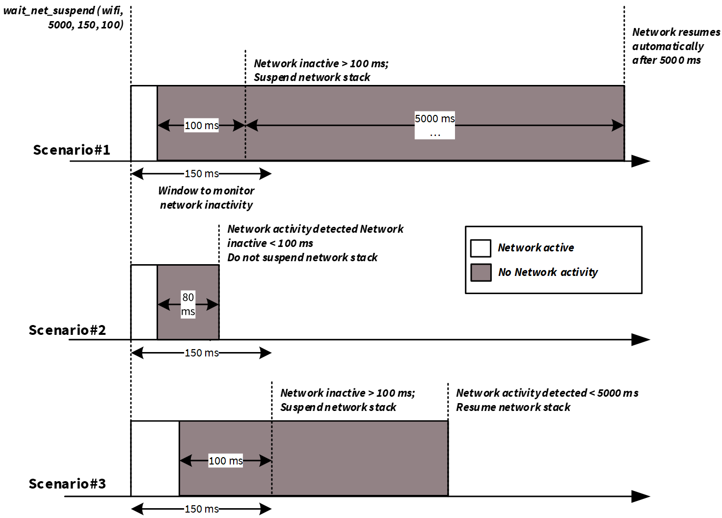
shows the suspend the network stack. operation in different scenarios with network suspend duration of 5000 ms, network inactivity monitor window of 150 ms, and network inactivity duration of 100 ms.
Scenario 1: wait_net_suspend()
detects no network activity for more than 100 ms within the 150 ms window and suspends the network. No network activity is detected for the network suspend duration of 5000 ms. Therefore,
wait_net_suspend()
resumes the network stack after 5000 ms.
Scenario 2: wait_net_suspend()
detects network activity in the 150 ms window and inactivity is less than 100 ms.
wait_net_suspend()
does not suspend the network stack.
Scenario 3: wait_net_suspend()
detects no network activity for more than 100 ms within the 150 ms window and suspends the network. Network activity is detected before the expiry of 5000 ms duration. Therefore,
wait_net_suspend()
resumes the network stack immediately.
Figure 5.
wait_net_suspend() operation
Host offloads to WLAN device
The AIROC™ CYW55513 Wi-Fi & Bluetooth® combo chip has an Arm® Cortex®-M33 core that performs all the WLAN device activities. It supports various offloads that execute certain functionalities on behalf of the host without interrupting the host state.
Host offloads play a key role in determining host power consumption because offloads let the host go into Deep Sleep for extended periods of time while the WLAN device handles tasks such as 802.11 roaming, ARP, IPv6 neighbor resolution, key rotation, DHCP Lease time renewal, NAT keepalives, NULL keepalives, Wake on wireless LAN, MQTT keepalives, and TCP keepalives on behalf of the host. In addition, these offloads free the host CPU for other, more powerful tasks such as audio or sensor data processing. This in turn improves the overall system efficiency and power.
The following sections describe offloads supported by AIROC™ CYW55513 Wi-Fi & Bluetooth® combo chip. The offloads can be enabled using the Infineon low-power assistant middleware. Using the LPA middleware in ModusToolbox™ is explained in
Low-Power Assistant (LPA)
section.
ARP offload
ARP is a data link layer protocol for mapping an IP address to a physical MAC address of a device. Such mapping is necessary for any WLAN device to keep updated on [IP:MAC] details of all nearby devices in its network. Using the ARP protocol, a device can detect duplicate IP addresses in a network. This is also useful in notifying peer devices of an IP address change.
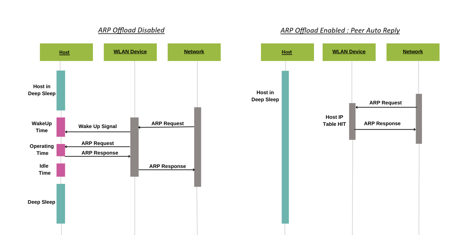
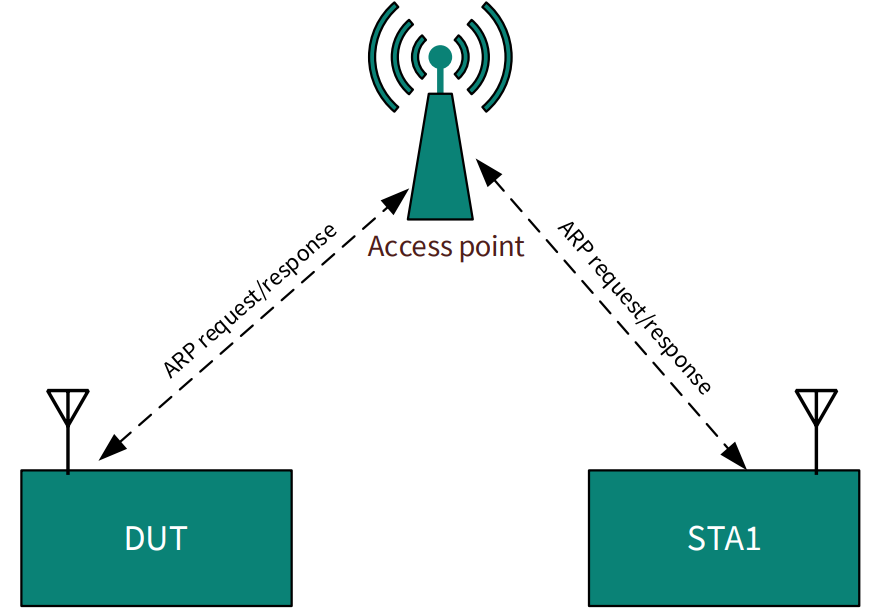
Because ARP request and response packets are a common activity in any WLAN network, the host device usually gets flooded by many requests; the host needs to remain active to respond to such requests, especially in a crowded network. ARP requests packets from a peer and usually wakes the host if it is sleeping. The ARP offloading feature in the AIROC™ Wi-Fi & Bluetooth® combo chip handles responding to ARP requests from a peer so that these requests will not disturb the host. The AIROC™ Wi-Fi & Bluetooth® combo chip device holds a cache (of eight entries); the host is woken up only if there is a cache miss as shown in
Figure 6
.
In addition to auto-replying to peers, AIROC™ Wi-Fi & Bluetooth® combo chip can use the cache to reply to the host (PSOC™ Edge MCU) as well when the host sends an ARP request to the network. The Host Auto Reply feature works similarly to Peer Auto Reply, where it responds to host ARP requests directly if a cache hit occurs, and if a cache miss occurs, the request is forwarded to the network, thereby reducing unnecessary broadcast traffic and conserving power. This feature is complemented by the ability of the AIROC™ Wi-Fi & Bluetooth® combo chip device to snoop ARP info from host-network communication, that is, whenever a host sends an ARP response packet over to the network, the [IP:MAC] information is cached into the AIROC™ Wi-Fi & Bluetooth® combo chip ARP cache table. ARP offload reduces the power consumption of your connected systems by reducing the time that the host needs to stay awake due to ARP broadcast traffic.
Figure 6.
ARP offload feature
Packet filter offload
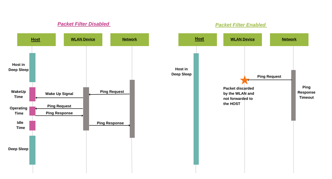
Packet filters are a crucial feature that enables the host processor to selectively allow or block specific types of packets from the WLAN subsystem, thereby conserving power and reducing unnecessary wake-ups. By configuring packet filters, the host processor can limit the types of packets that are passed up to it, preventing unrequired packets from waking it up from a power-saving System Deep Sleep mode or preventing it from entering this mode.
Packet filters are particularly useful when trying to keep the host processor in a low-power state for as long as possible or when trying to get it into this state as soon as possible. By filtering out unnecessary packets, the host processor can conserve power and reduce latency.
Supported packet filters are as follows:
Network layer/EtherType filters, which are based on the 16-bit EtherType field present in Ethernet packets
Internet Protocol (IP) filters, which are based on the 8-bit IP protocol number
Port filters, which are based on the 16-bit port numbers used by TCP and UDP applications
Transport layer/IP protocol filters, which filter based on the IP protocol number
Applications layer/TCP and UDP port numbers filters, which filter based on the port numbers used by TCP and UDP applications
Source port filters, which filter based on the source port numbers used by TCP and UDP applications
Destination port filters, which filter based on the destination port numbers used by TCP and UDP applications
Port range filters, which filter based on a range of port numbers used by TCP and UDP applications
ARP filters, which filter based on ARP packets
Internet Control Message Protocol (ICMP) filters, which filter based on ICMP packets
Transfer Control Protocol (TCP) filters, which filter based on TCP packets
User Datagram Protocol (UDP) filters, which filter based on UDP packets
IP filters, which filter based on IP packets
Action filters, which can be configured to either keep (send to host) or toss (drop/discard) packets
Each filter type has its own set of configuration options and considerations. For example, EtherType filters can be used to match specific protocols, such as ARP or IP, while IP protocol filters can be used to match specific protocols, such as TCP or UDP. Port filters can be used to match specific applications, such as SSH or FTP.
When configuring packet filters, it is essential to consider the specific requirements of the application and the network environment. For example, if the application needs to perform ping operations, then an IP protocol filter for ICMP must be enabled, along with an EtherType filter for ARP.
Packet filters can be used to enable or disable an approach to packet filtering, where only specific types of packets are allowed or blocked, respectively.
Figure 7.
Packet filter showing ICMP packet filter: Disabled vs. enabled
TCP keepalive offload
A TCP keepalive packet is a message sent by one device to another to check whether the link between the two is operational or to prevent the link from being disconnected. When two devices connect over a network via TCP/IP, TCP keepalive packets can be used to determine whether the connection is still valid and terminate if needed. If a connection has been terminated because of a TCP keepalive timeout and the other device eventually sends a packet for the old connection, the device that terminated the connection sends a packet with the RST flag set to signal the other device that the old connection is no longer active. This forces the other device to terminate its end of the connection, therefore, a new connection can be established. Therefore, TCP keepalive packets can be used in checking for dead peers or for preventing disconnection because of network inactivity.
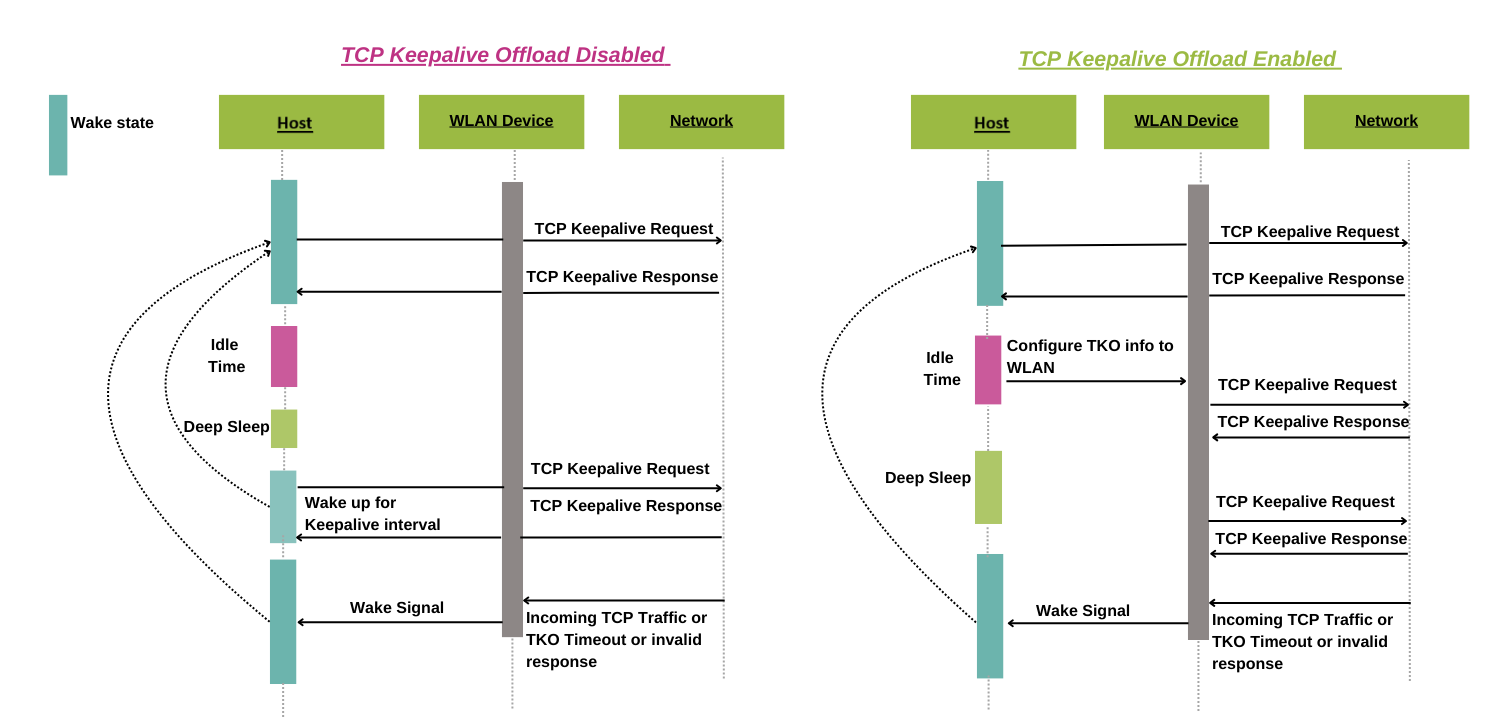
TCP keepalive offload: Typically, TCP keepalive packets are sent every 45 or 60 seconds on an idle TCP connection; the connection drops after three sequential ACKs miss. This means that the host MCU must wake up periodically to send TCP keepalive packets to maintain the TCP connection during the idle state. The TCP keepalive offloads part of the LPA help you improve the power consumption of your connected system by reducing the time the host needs to stay awake to support TCP keepalive requests. This is achieved by offloading the TCP keepalive functionality to the WLAN device so that the host MCU can be dedicated to your application.
Figure 8
shows that the host wakes up for incoming TCP traffic when offload is not enabled. On the other hand, the host can save more power by entering and staying in deep sleep for a longer time when the TCP keepalive activity is offloaded to the WLAN device.
Figure 8.
TCPKA offload: Disabled vs. enabled
DHCP Lease Time Renew offload
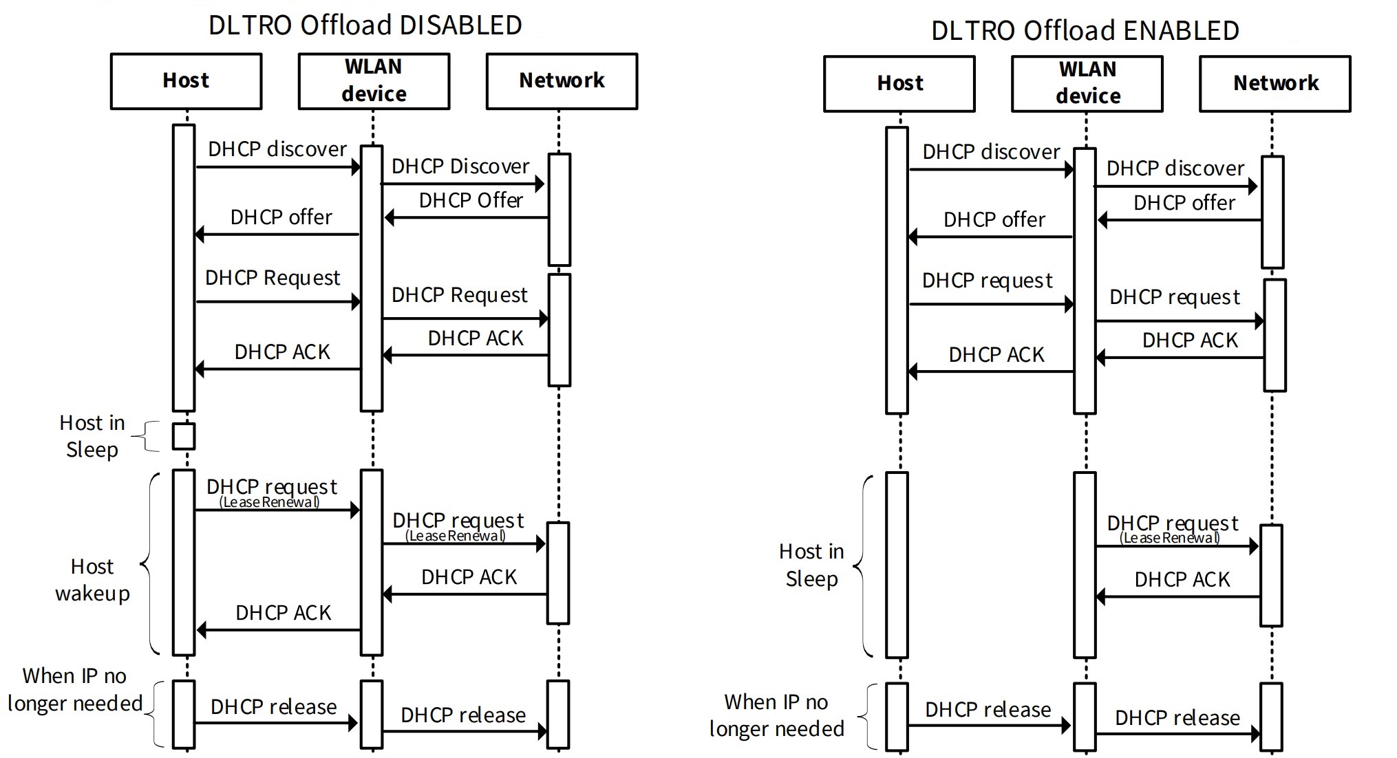
Dynamic Host Configuration Protocol (DHCP) is a network management protocol that dynamically assigns IP addresses to devices on a network, enabling them to communicate using IP. DHCP streamlines the process of assigning IP addresses to all network devices, eliminating the need for manual configuration. When a DHCP-enabled client joins a network, it broadcasts a DHCP Discover message, prompting the DHCP server to respond with a DHCP Offer containing essential IP configuration information, such as the default gateway, IP address, DNS server IP address, and lease time period. The client then sends a DHCP Request message to accept the offered IP address, which the server confirms with a DHCP Acknowledgment (ACK) message. The assigned IP address remains valid for the specified lease time interval, after which the client must renew the IP address by sending a DHCP Request message before the lease expires.
With DHCP Lease Time Renew offload, the WLAN firmware intercepts the DHCP Offer and records the DHCP lease time. When the MCU is in a sleep state, the firmware proactively sends a DHCP Request to the DHCP server before the lease time expires, reducing the need for the MCU to wake up periodically to renew the IP address. When the MCU is in a wake state, the DHCP renew packet is sent by the network stack running on the host.
By offloading DHCP Lease Time Renew to the WLAN firmware, the host device can conserve power and reduce the overhead associated with frequent wake-ups to renew IP addresses. DHCP Lease Time Renew offload can also help improve network reliability and reduce the risk of IP address conflicts, as the WLAN firmware can ensure timely renewal of IP addresses even when the host is in a sleep state.
Figure 9.
DLTRO offload: Disabled vs. enabled
ICMP offload
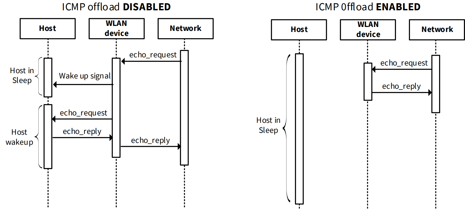
The Internet Control Message Protocol (ICMP) is a network layer protocol that enables network devices to troubleshoot communication issues by sending and receiving diagnostic messages. ICMP's primary function is to verify whether data packets are successfully reaching their intended destination by sending ICMP requests to a specific IP address and receiving timely responses. With ICMP offload, the WLAN firmware takes charge of responding to ICMP ECHO requests by sending PING ECHO response packets to the peer device without interrupting the host processor, allowing the host to remain in a low-power sleep state for an extended period. ICMP offload is active during both host wake and sleep states, ensuring seamless network communication.
By offloading ICMP processing to the WLAN firmware, the host device can conserve power and reduce latency, as it is no longer required to wake up and process ICMP requests. ICMP offload can also help improve network responsiveness and reliability, as the WLAN firmware can respond to ICMP requests in real-time, even when the host is in a sleep state.
Figure 10.
ICMP offload: Disabled vs. enabled
Neighbor Discovery (ND) offload
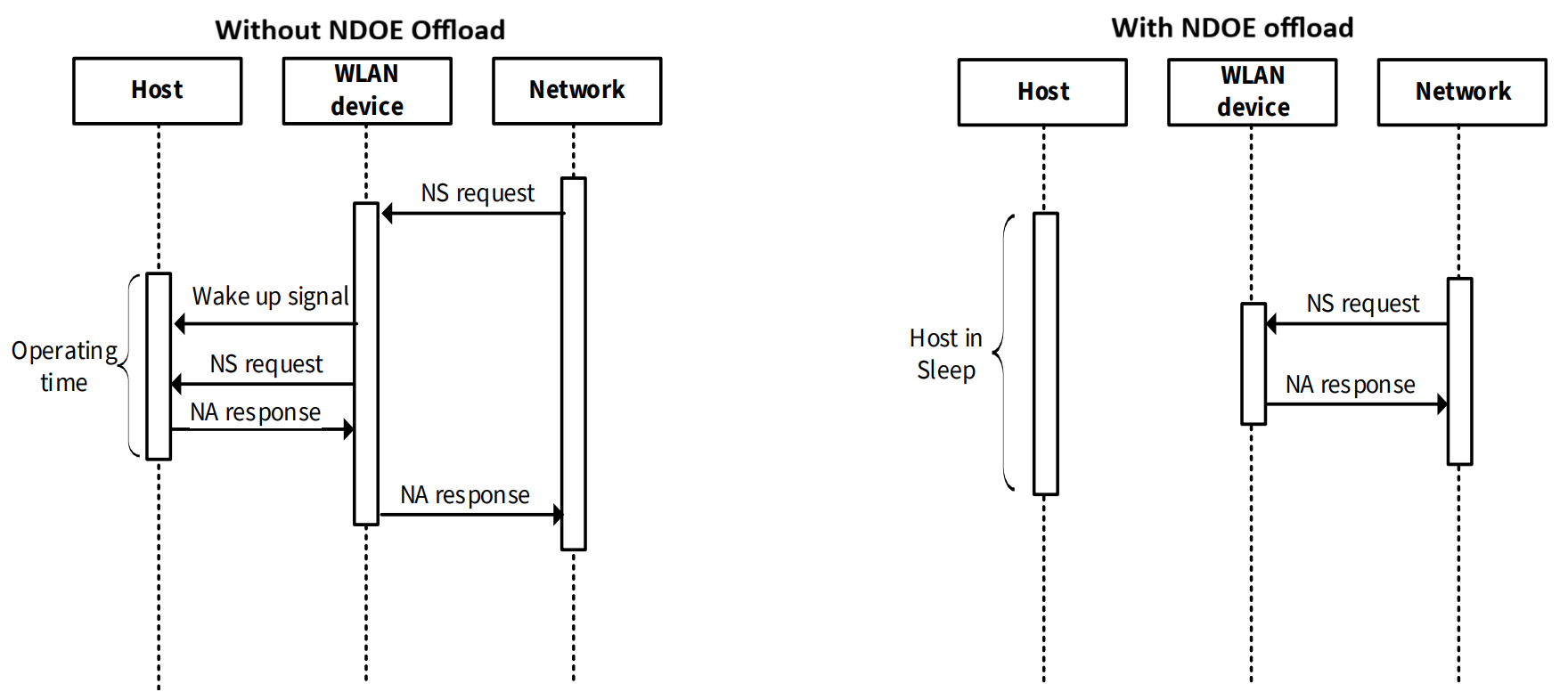
Neighbor Discovery (ND) is a network protocol used in conjunction with Internet Protocol Version 6 (IPv6) to enable nodes on the same link to discover and advertise their presence to neighboring devices. This protocol facilitates the exchange of link-layer addresses between nodes, similar to the Address Resolution Protocol (ARP) in IPv4.
Neighbor Solicitation (NS) messages are sent by a node to determine the link-layer address of a neighboring device or to verify the reachability of a cached link-layer address. These messages are also used for Duplicate Address Detection (DAD) to prevent IP address conflicts. In response to a Neighbor Solicitation, a node sends a Neighbor Advertisement (NA) message, which provides the MAC address associated with a specific IPv6 link-local address. Unsolicited Neighbor Advertisements are also sent to announce changes to a node's IPv6 link-local address. When a device is in a wake state, the network stack receives Neighbor Solicitation messages and responds with Neighbor Advertisement messages.
With Neighbor Discovery offload, the WLAN firmware assumes responsibility for responding to Neighbor Solicitation requests by sending Neighbor Advertisement packets to the peer device without waking up the host processor, allowing the host to remain in a low-power sleep state for an extended period.
By offloading Neighbor Discovery to the WLAN firmware, the host device can conserve power and reduce the overhead associated with processing Neighbor Solicitation messages, resulting in improved battery life and reduced latency.
Figure 11.
Network discovery offload: Disabled vs. enabled
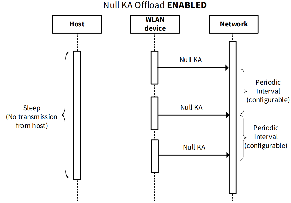
NULL keepalive offload
NULL keepalive is a mechanism designed to prevent wireless connections from being dropped due to inactivity. NULL keepalive packets are 802.11/L2 packets that are transmitted at regular intervals to maintain the wireless association/connection. With NULL keepalive offload, the WLAN firmware assumes responsibility for sending NULL keepalive packets at intervals specified by you. The default interval for NULL keepalive is 110 seconds, which is pre-configured in the WLAN firmware. You have the flexibility to adjust these intervals using the Device Configurator, with the constraint that the interval value must fall within the range of 1 second to 4200 seconds.
The power consumption of the device can be further optimized by adjusting the interval value for NULL keepalive packets, as a longer interval can result in lower power consumption, but may also increase the risk of connection drops.
Figure 12.
Flow of null keepalive transmit
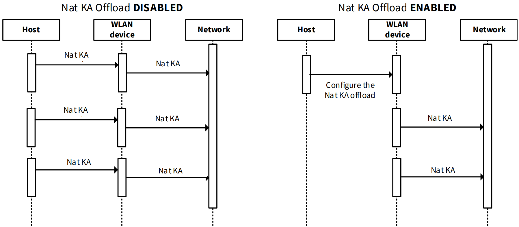
NAT keepalive offload
NAT keepalive periodically sends small UDP packets between the client and server to maintain the NAT tables in routers, ensuring smooth packet forwarding and preventing packet drops due to idle timeouts. With NAT keep-alive offload, the WLAN firmware (FW) takes over the responsibility of sending keepalive packets at regular intervals, even when the host is in a sleep state. This feature is active in both host sleep and wake states.
NAT keepalive offload can help reduce the host's power consumption by offloading the keepalive packet transmission to the WLAN firmware, allowing the host to remain in a low-power state for longer periods. The configured interval for sending keep-alive packets can be adjusted to balance between maintaining NAT table entries and minimizing network traffic.
Figure 13.
NATKA offload: Disabled vs. enabled
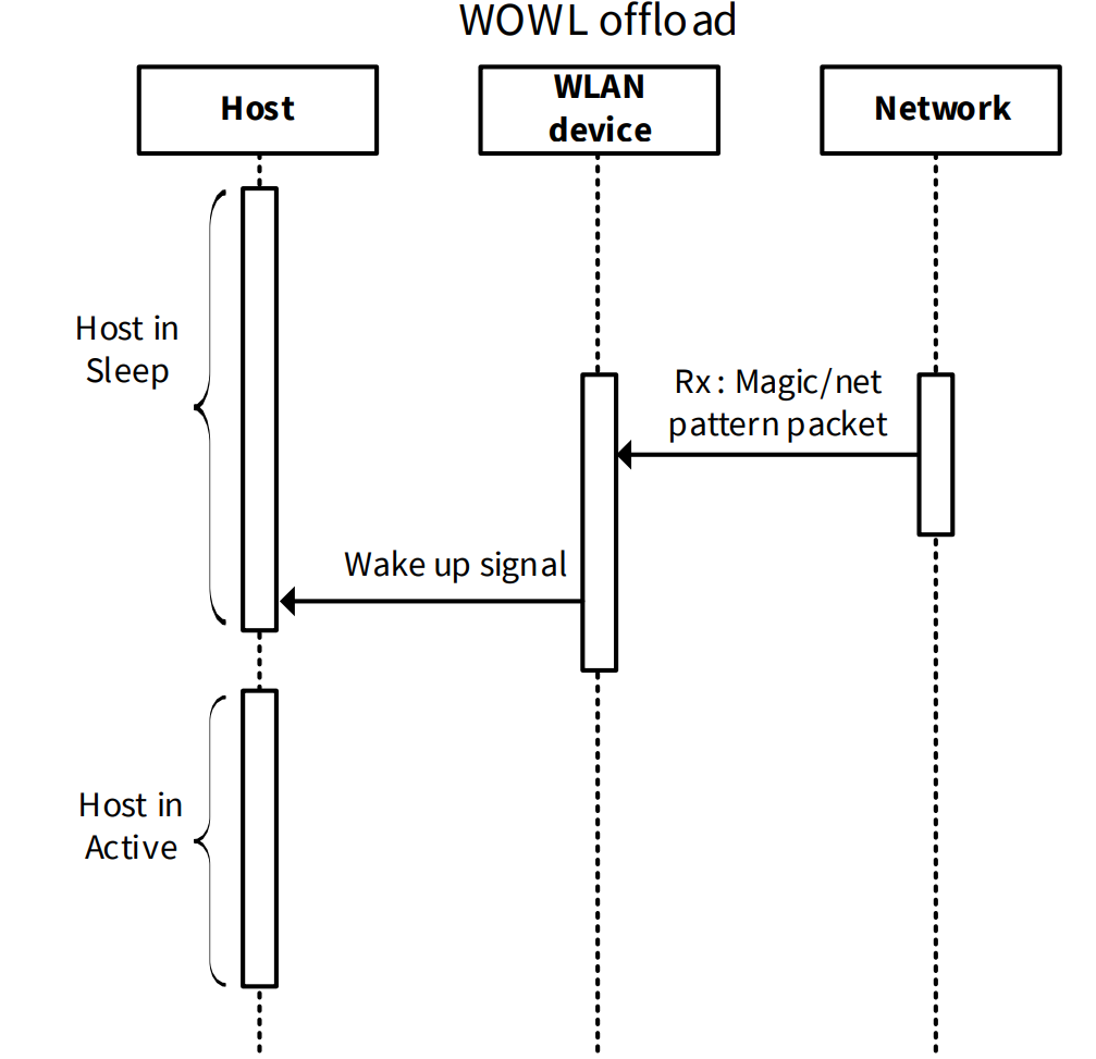
Wake on Wireless LAN
Wake on Wireless LAN (WOWL) allows a host to be turned on or awakened when a WLAN firmware receives a specific network message from the Access Point (AP). This feature is enabled when the host is in a low-power state, enabling the device to conserve energy. The intention of WOWL is to allow the host to enter a sleep mode and wake up only when a specific packet is received, reducing power consumption.
Wake on Magic Pattern:
When a magic packet is received, the WLAN firmware wakes up the host. The magic packet is a broadcast packet containing a payload of 6 bytes of all 255 (FF FF FF FF FF FF in hexadecimal), followed by sixteen repetitions of the target 48-bit MAC address. This feature is particularly useful for remote management and maintenance.
Wake on Net Pattern:
This feature wakes up the host when the packet received in the WLAN matches the configured net pattern, mask, and offset. This allows for more flexibility and customization in determining which packets can wake up the host.
Wake on Pattern Configuration:
By configuring wake on patterns, the host can remain in a sleep state for longer periods without waking up for incoming packets, resulting in significant power savings.
Wake on Unicast:
This feature allows the host to wake up when a unicast packet is received, providing an additional option for waking up the host.
WOWL Timeout:
A configurable timeout can be set to determine how long the host remains in a sleep state before waking up, providing more control over power management.
Figure 14.
Basic flow exchange in wake-on-WLAN
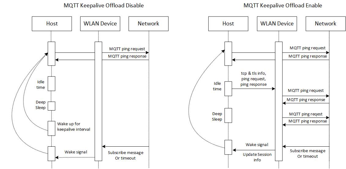
MQTT keepalive offload
MQTT keepalive offload is a feature of the Low-Power Assistant (LPA) tool that reduces power consumption by minimizing the time the host needs to stay awake to support MQTT keepalive requests, which is achieved by offloading the keepalive functionality to the WLAN firmware, allowing the host MCU to remain in Sleep mode and only wake up when an MQTT message containing a pre-configured pattern is received.
Figure 15.
MQTT offload: Disabled vs. enabled
Bluetooth® power optimization techniques
AIROC™ CYW55513 Wi-Fi & Bluetooth® combo chip supports a Bluetooth® 5.3 + BR/EDR-compliant/Bluetooth® LE radio.
Common operations related to power consumption in a Bluetooth® LE application include advertisement and connection events. It is discussed how to optimize various parameters related to both advertisement and connection events to reduce power consumption. This section assumes that you are familiar with Bluetooth® LE fundamentals. See Vol 6: “Core System package [Low Energy Controller]” of the latest
Bluetooth® Core specification
for Bluetooth® LE fundamentals.
Bluetooth®
Configurator
The Bluetooth® Peripheral/Central has an additional configurator called the “Bluetooth® Configurator”; used to generate the AIROC™ Bluetooth® LE GATT database and various Bluetooth® settings for the application. These settings are stored in the file named
design.cybt
. Note that, unlike the Device Configurator, the Bluetooth® Configurator settings, and files are local to each respective application.
For detailed information on how to use the Bluetooth® Configurator, see the
Bluetooth® Configurator guide
.
Advertisement events
Advertisement events broadcast the capabilities of a Bluetooth® LE Peripheral device to Bluetooth® LE Central devices listening to the events. These events can constitute the major portion of a Bluetooth® device’s battery consumption, if not carefully chosen. The interval between two successive advertisement events from the Peripheral forms the advertising interval; it can be fixed or a random value between a min and maximum interval.
To achieve the lowest possible power during advertisement events, you should maximize the advertising interval. However, a larger advertising interval leads to a longer detection time at the Central device and a subsequently longer time for getting connected to the Central. The advertising interval should be between 20 ms and 10.24 seconds. In addition, the advertisement interval between a min and maximum not only improves the tradeoff between power and latency, but also improves the detection probability in noisy environments by randomizing the time at which an advertisement packet is sent out.
Using Bluetooth® Configurator, the advertisement packet duration or interval can be set.
Application requirement | Suggested advertisement interval |
|---|---|
The application requires shorter detection and connection establishment periods such as audio devices or devices that send real-time data | 20 to 100 ms |
The application does not have aggressive connection requirements but still prefers low latency such as fitness trackers or smart watches | 100 to 1000 ms |
The application does not care about latency; power consumption is of more importance, such as in the case of beacons | 1000 to 10000 ms |
In addition to the advertisement interval, the amount of data transmitted during advertisement impacts the power consumption during advertisement events. The smaller the advertisement payload, the lower the power consumption.
Connection events
Connection interval
The connection interval for a Bluetooth® LE link is set by the Central device when a connection is created with the Peripheral device. The Peripheral should have a connection interval that matches the rate at which the sensor data from the Peripheral is sent to the Central device. If the initial connection interval set by the Central is lower than necessary, the Peripheral should request the Central to increase the connection interval to reduce current consumption. This can be done after a connection is established by sending a “connection parameter update request” to the Central.
Use Peripheral latency
Peripheral latency is a Bluetooth® LE feature that allows a Peripheral to listen to the Central device on connection events at a reduced rate. This is useful if the Peripheral device is inactive for some time and has to wait for some activity to occur to send data to the Central device. If no activity is detected for some time, the Peripheral can enter Peripheral latency by sending a connection update request to the Central device. The Peripheral can extend the interval between connection events at which it listens to the Central. This allows the Bluetooth® LE device and the host to be put into Deep Sleep mode for longer durations.
The key advantage of using Peripheral latency is that when the peripheral application detects activity, it can switch the Bluetooth® LE device back ON to listen to the Central at the original connection interval until the data transfer is completed. This avoids the latency in sending the data upon the first activity.
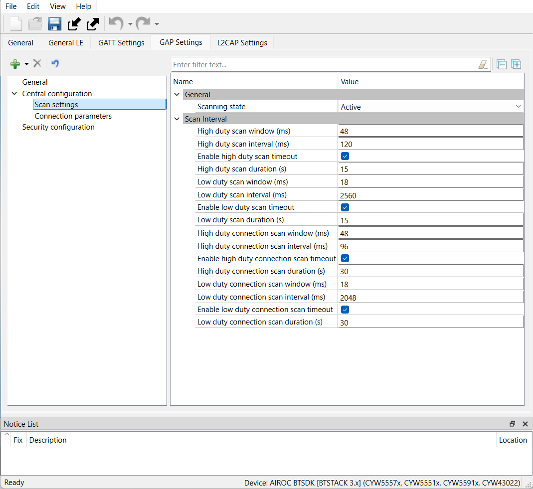
Bluetooth® LE parameters in Bluetooth® Configurator
,
Figure 17
, and
Figure 18
show the configurations of connection parameters, advertisement settings, and scan settings respectively.
Adjusting these parameters can minimize power consumption by keeping the device in low power mode for longer periods, only waking up when required. Refer
PSOC™ Edge MCU: Bluetooth® LE CTS Server code example
and
PSOC™ Edge MCU: Bluetooth® LE CTS Client code example
for more information on power consumption across various modes.
Figure 16.
Connection parameters in Bluetooth® Configurator
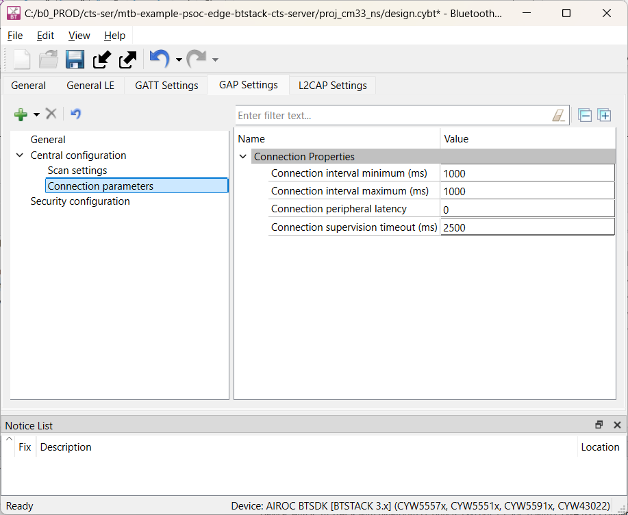
Figure 17.
Advertisement settings in Bluetooth® Configurator
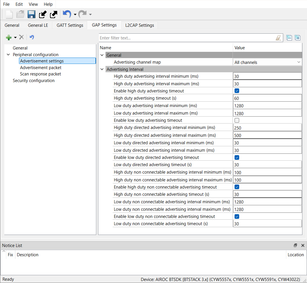
Figure 18.
Scan settings in Bluetooth® Configurator
Low-Power Assistant (LPA)
The Infineon Low-Power Assistant (LPA) tool allows configuring PSOC™ Edge MCU host and WLAN (Wi-Fi/Bluetooth® radio) devices to provide low-power features. Key highlights of the LPA include the following:
Self-aware firmware that detects configurations automatically and enables appropriate low-power features without any additional API calls
Supports embedded operating systems, such as FreeRTOS
GUI-based configuration for ease of use
Supports low-power configuration for PSOC™ Edge MCU, Wi-Fi, and Bluetooth®
LPA lets you optimize various parts of your design to be energy-efficient. The LPA configuration is split into three main parts:
PSOC™ Edge MCU (host) low-power configuration:
Includes PSOC™ Edge MCU-specific low-power configurations, such as core voltage, regulator selection, and RTOS idle power mode
Wi-Fi low-power configuration:
Includes Wi-Fi-specific low-power configurations, such as Wi-Fi host wake signal selection and host offload configurations
Bluetooth® low-power configuration:
Includes Bluetooth® low-power configurations, such as host wake interrupt signal (device to host) and related device integration
Some of these configurations are already part of the firmware and some can be generated through the Device Configurator in ModusToolbox™ software or added manually through code. Given the simplicity of the configurations, adding them through a code is not difficult. However, using the configurator lets you take advantage of a GUI-based configurator in addition to making the generated configuration easily upgradable in the future; it is the recommended way to create low-power configurations.
See the
LPA documentation
for details on the middleware, configurators, and quick start.
The following sections provide a brief on the Wi-Fi, and Bluetooth® low-power configurations available and their usage in different platforms.
LPA configuration
To configure Low-Power Assistant (LPA) settings, some configurations are included in the firmware by default, while others require explicit enablement through the Device Configurator tool, which is part of the ModusToolbox™.
To access the Device Configurator, you can launch it from within ModusToolbox™. Once you have made the necessary configurations, the settings are saved to a file named
design.modus
. This file contains the configuration details for the LPA settings, as well as other device configurations, and can be used to generate the firmware for your device
To check the LPA settings, open
settings
Figure 19
shows the PSOC™ Edge MCU and Wi-Fi LPA (power) settings for the
TARGET_KIT_PSE84_EVAL_EPC2
target. You need to enable the
Power
setting to enable LPA configuration generation. For a detailed description of all the configurations, see the
LPA documentation
Figure 19.
PSOC™ Edge MCU LPA configurations in
design.modus
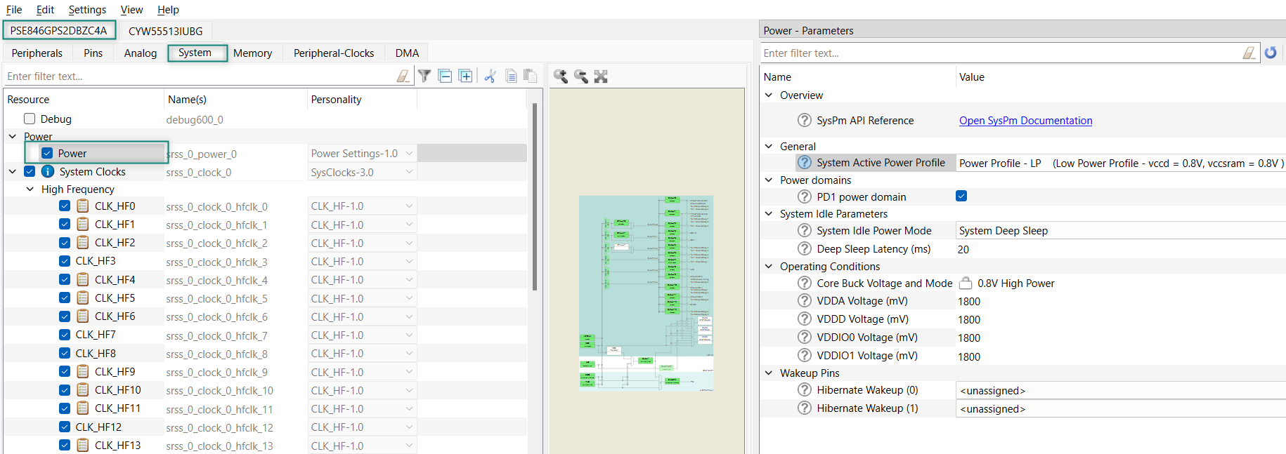
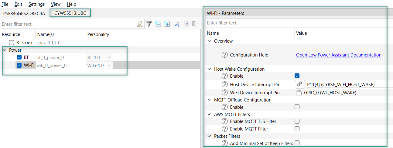
Figure 20.
Wi-Fi/Bluetooth® LPA configuration in
design.modus
Power measurement using KIT_PSE84_EVAL_EPC2
Hardware setup
For power measurement, use a DC power analyzer such as
N6705B
from Keysight because it gives insights on power transitions and a better estimate of power saving achieved. If you do not have access to a power analyzer, use a simple 6 ½-digit multimeter to monitor the PSOC™ Edge MCU and WLAN average power individually.
Do the following for power measurement in KIT_PSE84_EVAL_EPC2:
PSOC™ Edge E84 Evaluation Kit is a generic kit to evaluate the PSOC™ Edge MCU features. To particularly measure the current consumption for this code example, the following changes are required on the hardware.
Remove resistor R188 (680 ohm) on the PSOC™ Edge E84 SOM to disable the connectivity to power LED (D3) on the SOM
Remove resistor R90 (10k ohm) and populate resistor R93 (4.7k ohm) on the PSOC™ Edge E84 SOM to disable the JTAG connected to AIROC™ CYW55513 module
Remove resistor R415 (0 ohm) on the KIT_PSOCE84_EVK to measure the AIROC™ CYW55513 VBAT current across it
Connect wires across J25 (VBAT) and J26 (VDDIO) on PSOC™ Edge E84 Evaluation Kit's baseboard to a power analyzer to measure the power consumed by the PSOC™ Edge E84 MCU
Similarly, connect wires across R415 on PSOC™ Edge E84 Evaluation Kit's baseboard to a power analyzer to measure the current consumed by the AIROC™ CYW55513 connectivity module
PSOC™ Edge MCU: WLAN low-power code example
This section describes power measurement in KIT_PSE84_EVAL_EPC2 with the PSOC™ Edge MCU: WLAN low power code example
1
. This example can be used to measure AIROC™ CYW55513 Wi-Fi & Bluetooth® combo chip power consumption as documented in the datasheet.
By default, the example configures the AIROC™ CYW55513 Wi-Fi & Bluetooth® combo chip in Power Save Without Poll (PS-non-Poll) mode for better throughput and suspends the network stack so that PSOC™ Edge MCU remains in Deep Sleep for as long as no activity is detected in the network.
Set up the KIT_PSE84_EVAL_EPC2 kit as explained in the
Hardware setup
section. Note that this section uses a Keysight N6705B as the reference setup to measure power
Turn on the channels to power the PSOC™ Edge MCU and AIROC™ CYW55513 Wi-Fi & Bluetooth® combo chip from the N6705B power analyzer from Keysight
Follow the
README
instructions provided in the PSOC™ Edge MCU: WLAN low power code example
1
. Build and program the code example. After programming, the application starts automatically.
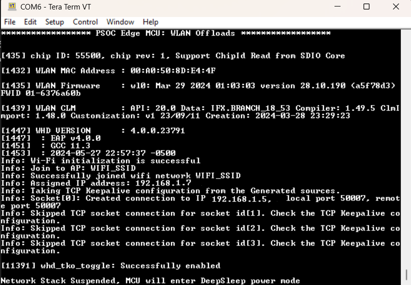
Figure 21
and
Figure 22
show the outputs respectively. You can connect the onboard KitProg for viewing logs in terminal software through the COM port
Ensure that the configured Wi-Fi AP is in range and the device connects to it
Figure 21.
Connected to AP and suspended the network stack
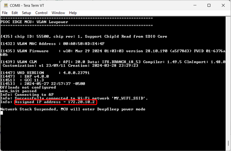
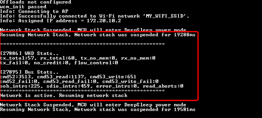
Figure 22.
Resuming the network stack
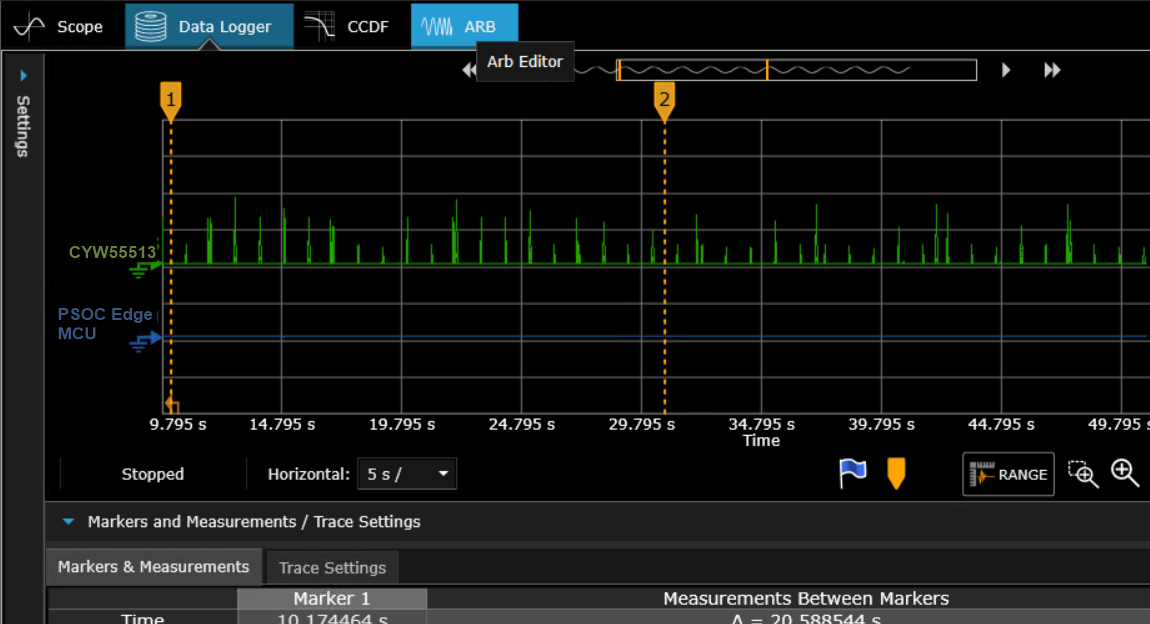
Turn on the Power Analyzer to see the current consumption across the AIROC™ CYW55513 connectivity module and the PSOC™ Edge E84 MCU as shown in
Figure 23
.
The spikes in the current across the AIROC™ CYW55513 connectivity module is due to the beacons sent by the AP. The interval and amplitude of this beacon will vary based on the DTIM value, beacon interval, and frequency set in the router's configuration.
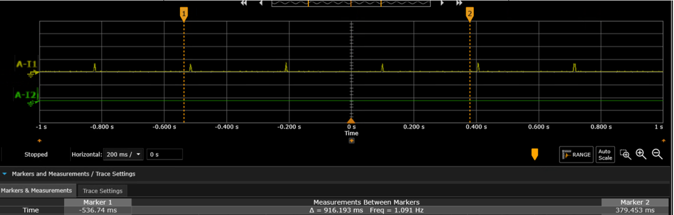
Figure 23.
Sample Power Analyzer output
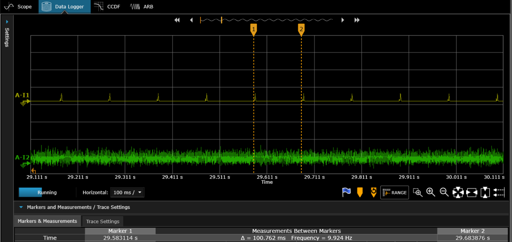
Note that in
Figure 23
, the yellow pulse represents the current consumed by the AIROC™ CYW55513 connectivity module and the green pulse represents the current consumed by the PSOC™ Edge E84 MCU.
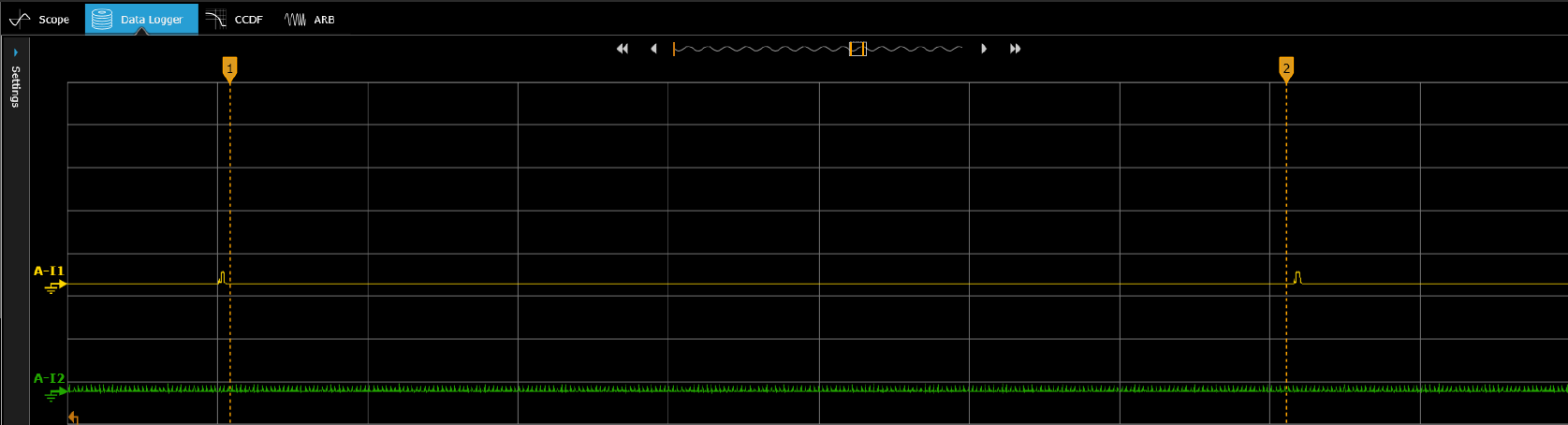
Measure the sleep current (with default router settings) between any two DTIM intervals in the AIROC™ CYW55513 module's current as shown in
Figure 24
.
Figure 24.
Measuring the Deep Sleep current
Enter the router's configuration page and set DTIM = 1, beacon interval = 100, and 2.4 GHz frequency and measure the average current over 3 DTIM intervals as shown in
Figure 25
.
Figure 25.
Average current over 3 DTIM periods for AP (2.4 GHz) beacon interval of 100 and AP DTIM of 1
Similarly, vary the DTIM to 3 and the frequency of the Wi-Fi router to 5 GHz and measure the current consumptions across AIROC™ CYW55513 connectivity module and PSOC™ Edge E84 MCU.
The power measurement of the PSOC™ Edge MCU in Deep Sleep state is 920.49 μW, measured across VBAT (3.3 V) and VDDD (1.8 V). This represents the total power consumption in the Deep Sleep state.
Note:
These power values are not optimized for low power. See the
PSOC™ Edge MCU: Power measurements
code example for MCU power optimization.
State | Device | Current |
|---|---|---|
Sleep | AIROC™ CYW55513 (VBAT) | 54.45 μA |
Average current for this AP configuration (2.4 GHz) beacon interval of 100 and AP DTIM of 1 | AIROC™ CYW55513 (VBAT) | 715.46 μA |
Average current for this AP configuration (2.4 GHz) beacon interval of 100 and AP DTIM of 3 | AIROC™ CYW55513 (VBAT) | 253.57 μA |
Average current for this AP configuration (5 GHz) beacon interval of 100 and AP DTIM of 1 | AIROC™ CYW55513 (VBAT) | 540.26 μA |
Average current for this AP configuration (5 GHz) beacon interval of 100 and AP DTIM of 3 | AIROC™ CYW55513 (VBAT) | 220.24 μA |
PSOC™ Edge MCU: WLAN offloads code example
This section describes power measurement in KIT_PSE84_EVAL_EPC2 with the PSOC™ Edge MCU: WLAN offloads code example
2
. This code example demonstrates various WLAN offloads as mentioned in
Host offloads to WLAN device
of Section 3, which are offered by Infineon AIROC™ Wi-Fi devices using PSOC™ Edge MCU.
This code example focuses on Wi-Fi WLAN offloads. These features offloads to the WLAN device, allowing the host MCU to enter Sleep and Deep Sleep states. Therefore, reducing the overall system power consumption.
By default, all WLAN offloads are enabled.
Set up the KIT_PSE84_EVAL_EPC2 kit as explained in the
Hardware setup
section. Note that this section uses the N6705B power analyzer from Keysight as a reference setup to measure power
Turn on the channels to power PSOC™ Edge MCU andAIROC™ CYW55513 Wi-Fi & Bluetooth® combo chip from N6705B. You can connect the onboard KitProg to view logs in terminal software through the COM port
Ensure that the configured Wi-Fi AP is in range and that the device connects to it
To realize the capability of WLAN offloads and their impact on the host MCU in terms of power savings, the current measurement has been done by considering the following cases
To simulate a congested network environment, another Wi-Fi client device has associated to the same network to which the target kit has associated. In all these current measurement cases, the role of the client device is to send ping and ARP request packets periodically in its configured interval to the IP address of the target kit. Based on whether the LPA offloads are enabled, the host MCU stays in Deep Sleep power mode or wake up due to the ping and arp-ping requests from the client device
WLAN offloads can be enabled or disabled in the Wi-Fi parameters using the Device Configurator
Follow the
README
instructions provides in the code example
2
. Build and program the code example. After programming, the application starts automatically.
Figure 26
shows the output respectively
AP configuration:
DTIM: 3
Beacon Interval: 100 ms
Band: 2.4 GHz
Wireshark setup for monitoring air logs
In this test setup, air sniffer (NUC) is used to monitor the Wireshark logs, which allows to monitor and inspect wireless network traffic, including Wi-Fi packets in real-time
Connect the air sniffer to a monitor or a display device to view the logs
Open Wireshark on the air sniffer, either by launching the application or downloading and installing it from the official website if you have not already
Filter the captured packets using the IP address, MAC address, or offload to focus on the specific traffic of interest
Figure 26.
WLAN offloads terminal output
Case 1: ARP offload
ARP offload is enabled in the firmware by default.
Figure 27.
Verify ARP offload
Verify the functioning of ARP offload by sending an ARP request packet from the command prompt of your PC. Observe that the responses are received from the WLAN device without interrupting the host MCU from Deep Sleep.
$ arp-ping 192.168.1.7
Reply that E8:E8:B7:A0:29:1C is 192.168.1.7 in 0.434ms
Reply that E8:E8:B7:A0:29:1C is 192.168.1.7 in 0.103ms
Reply that E8:E8:B7:A0:29:1C is 192.168.1.7 in 0.109ms
Reply that E8:E8:B7:A0:29:1C is 192.168.1.7 in 0.124ms
Figure 28.
Monitoring ping activity
Case 2: Packet Filter offload
shows the configurations to enable Packet filter offload from the Device Configurator.
Figure 29.
Packet Filter Configuration 1
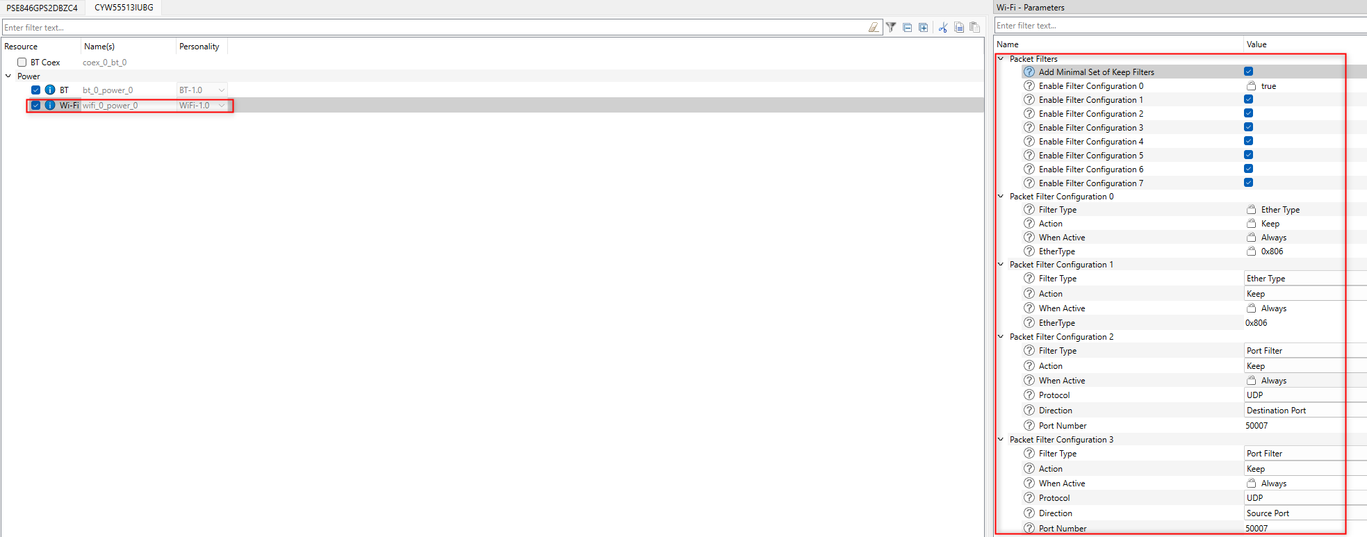
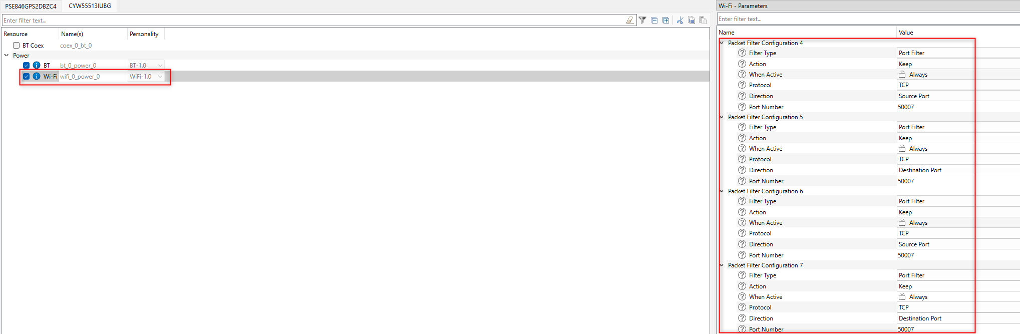
Figure 30.
Packet Filter Configuration 2
Normally, without packet filters, the WLAN subsystem passes all packets destined for the host up to the host network stack for processing. If the host is in System Deep Sleep, the WLAN subsystem will first wake the host, and then pass the packet up to the stack. From there, the network stack will pass the packet on to the application that is listening for that type of packet. If no applications are listening for that type of packet, the network stack drops the packet.
$ ping 192.168.1.7
Pinging 192.168.1.7 with 32 bytes of data:
Request timed out.
Request timed out.
Request timed out.
Request timed out.
Ping statistics for 192.168.1.7:
Packets: Sent = 4, Received = 0, Lost = 4 (100% loss),
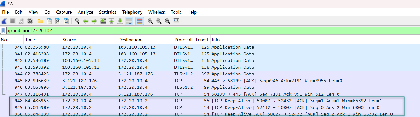
Case 3: TCP keepalive offload
TCP keepalive offload is enabled in the firmware by default. Verify the logs of the TCP connection in
Figure 31
. Verify if the TCP connection is established as shown in
Figure 31
.
Use the Wireshark Sniffer tool for capturing TCP keepalive packets on Windows, Ubuntu, and macOS. The DUT receives the TCP keepalive packets as configured as shown in
Figure 31
.
Figure 31.
TCP keepalive packet logs
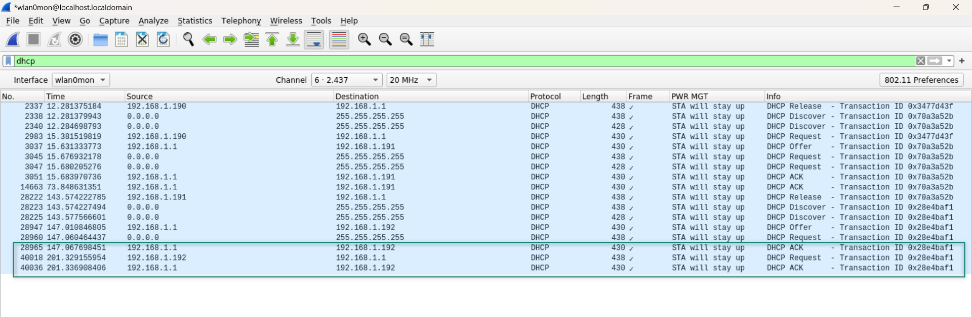
Case 4: DHCP Lease Time Renew offload
This offload is enabled by default in the firmware. You can edit the DHCP lease time in the router settings. In this case, the DHCP lease time is set to 60 seconds in the router settings. Check the Wireshark if the packets are being transmitted in the respective time.
Figure 32
shows the DHCP renewal packets sent every 60 seconds as configured.
Figure 32.
DHCP Lease Time Renewal logs
Case 5: ICMP offload
ICMP offload is enabled in the firmware by default. It allows the AIROC™ CYW55513 device to serve ICMP ping requests directly from the chip, instead of waking the host.
$ ping 192.168.1.7
Pinging 192.168.1.7 with 32 bytes of data:
Request timed out.
Request timed out.
Request timed out.
Request timed out.
Ping statistics for 192.168.1.7:
Packets: Sent = 4, Received = 0, Lost = 4 (100% loss),
Case 6: Neighbor Discovery offload
Neighbor Discovery offload is enabled by default in the WLAN firmware. Therefore, it is not required to do any configuration settings in ModusToolbox™ Device Configurator. Use the
ifconfig
command to verify whether the IPv6 address is up. Alternatively, you can manually assign a static IP address using the following command:
ip -6 addr add fe80::0290:4cff:fec5:1239/64 dev wlan0
Connect the STA1 device to the same AP.
On STA1, initiate IPv6 neighbor discovery using the following command from a neighbor device:
ndisc6 <dut_ipv6> wlan0
Figure 33.
Neighbor Discovery offload logs
Case 7: NULL keepalive offload
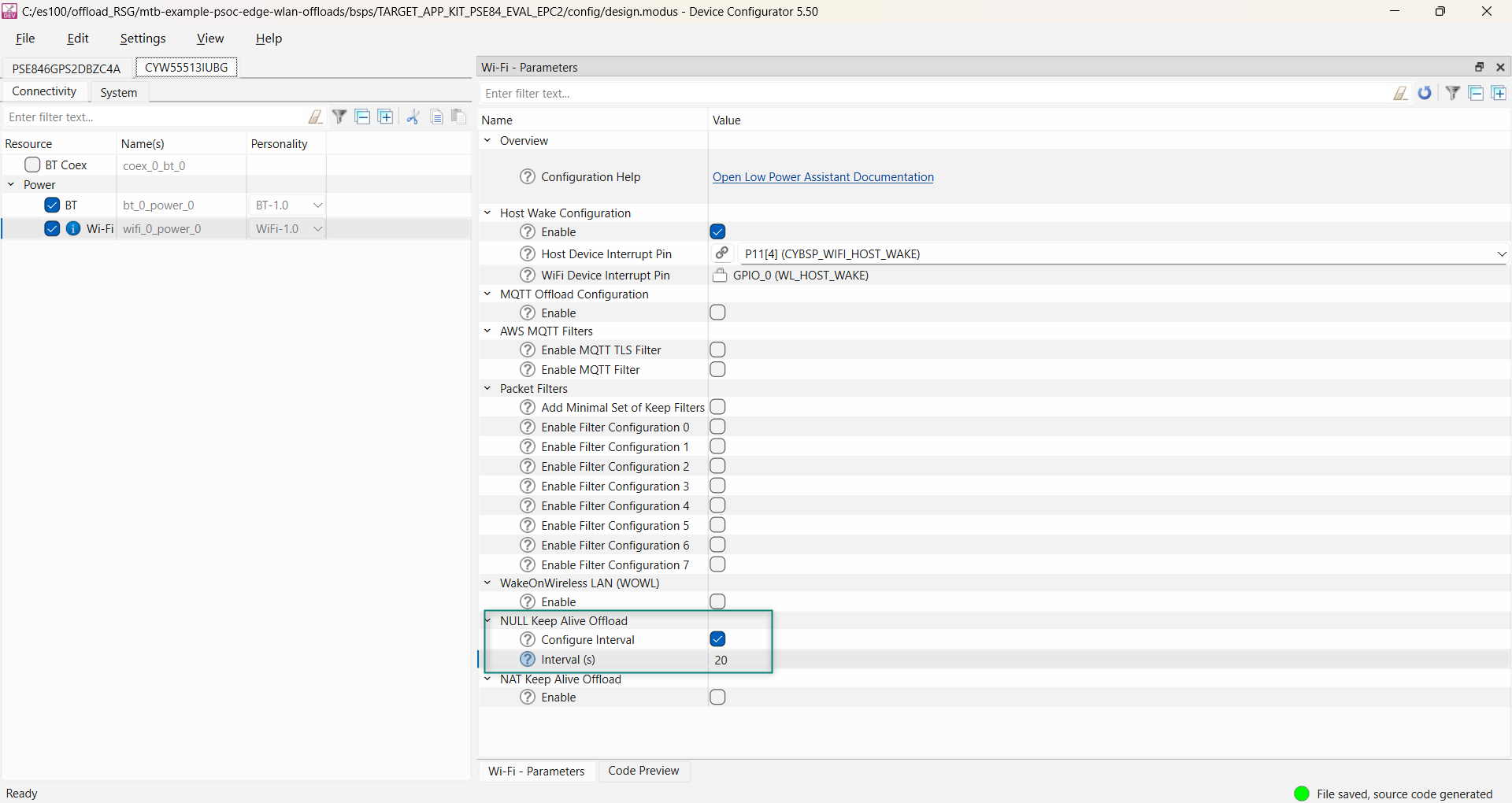
Enable this offload in the Device Configurator.
Figure 34
shows the configurations to enable NULL keepalive offload.
Figure 34.
Null keepalive offload configurations
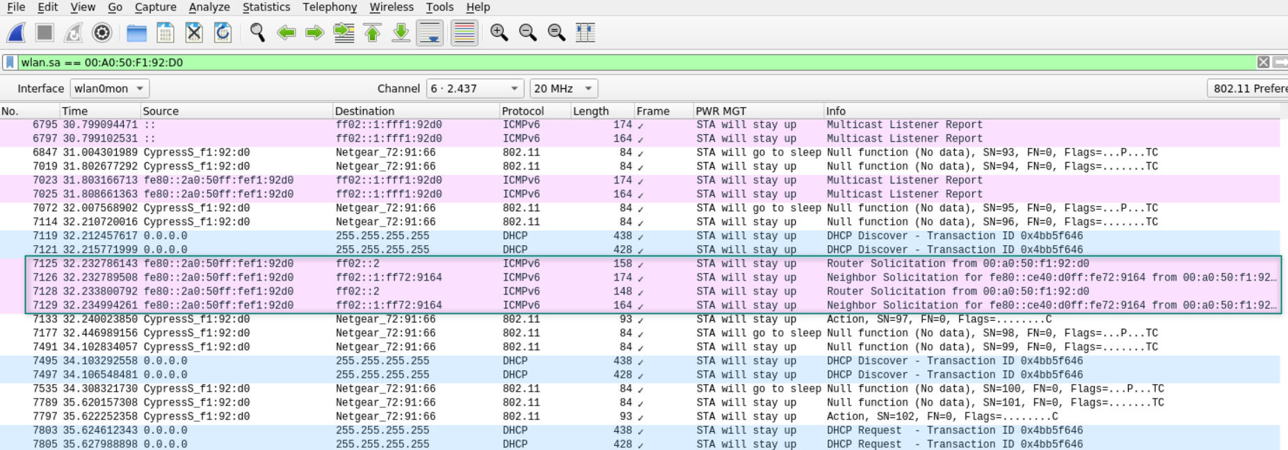
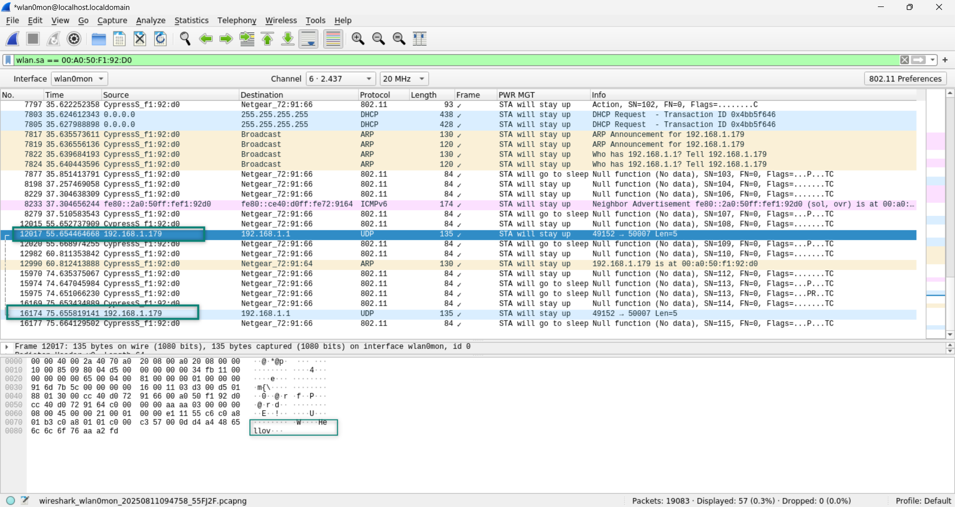
highlights NULL keepalive packets sent every 20 seconds that is configured in the Device Configurator. These packets are sent as null data frames containing no payload. The AIROC™ CYW55513 combo chip sends null keepalive packets at a periodic interval to the AP without exiting Deep Sleep.
Figure 35.
Null keepalive offload logs
Case 8: NAT keepalive Offload
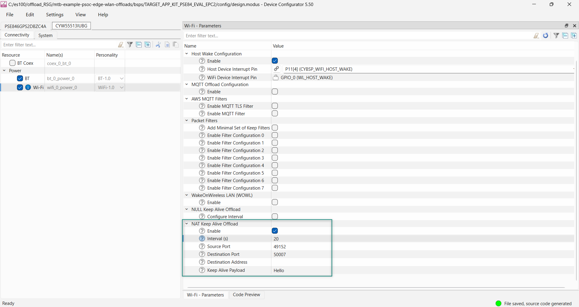
Enable offload is to be enabled in the Device Configurator.
Figure 36
shows the configurations to enable NAT Keepalive offload.
Figure 36.
NAT keepalive configurations
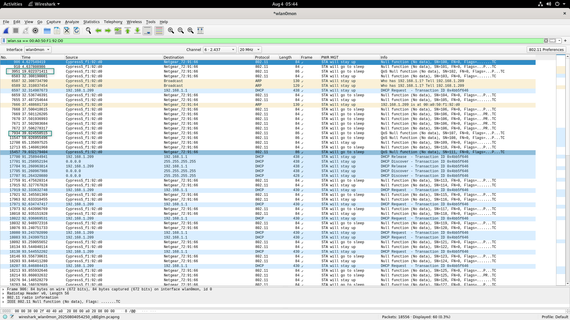
highlights NAT keepalive packets sent every 20 seconds with the payload that is configured in the Device Configurator. NAT keepalive packets are used to maintain the NAT mapping between a private IP address and the public IP address of a device. The AIROC™ CYW55513 combo chip sends NAT keepalive packets at a periodic interval to the AP without waking up the host.
Figure 37.
NAT keepalive offload logs
Case 9: Wake On Wireless LAN
Enable this offload in the Device Configurator.
Figure 38
shows the configurations to enable WOWL.
Figure 38.
WOWL configurations
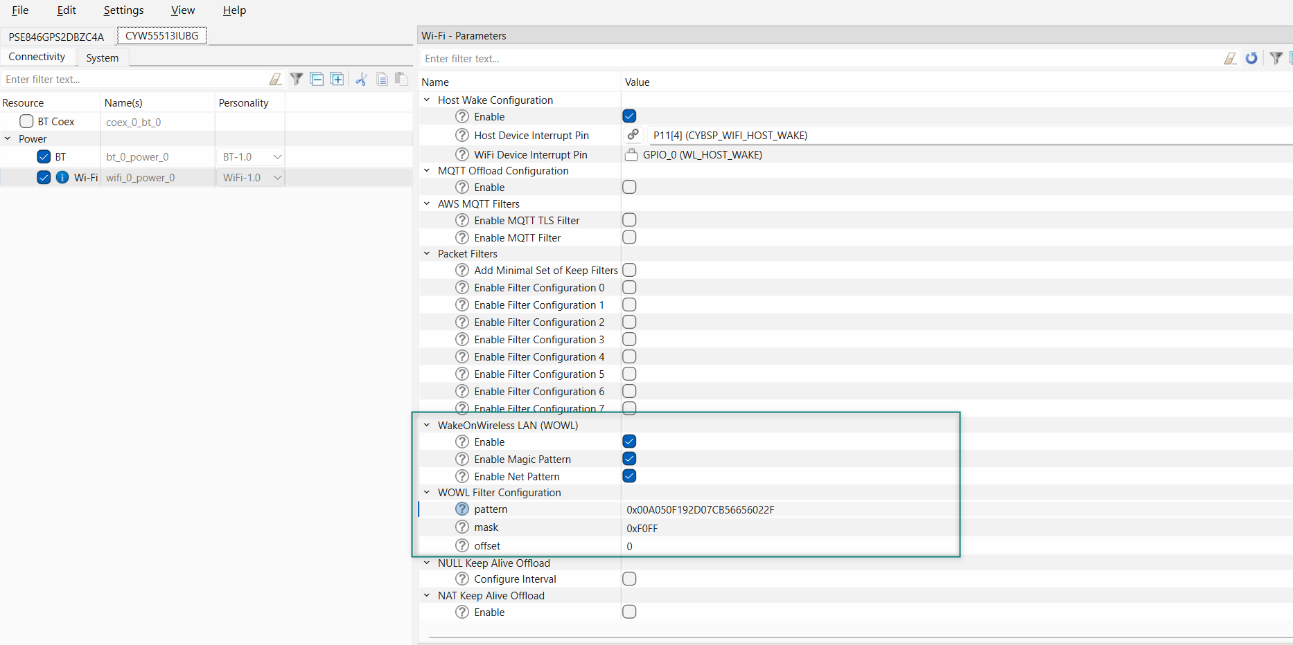
The magic pattern should be as follows:
f"0x(dut_mac_pattern)(peer_mac_pattern)"
To verify, send the Ethernet packet from the peer containing the pattern and monitor that MCU wakes-up for only the configured pattern.
Case 10: MQTT keepalive offload
Enable MQTT offload from the Device Configurator.
Figure 39
shows the configurations to enable MQTT offload.
Figure 39.
MQTT offload configurations
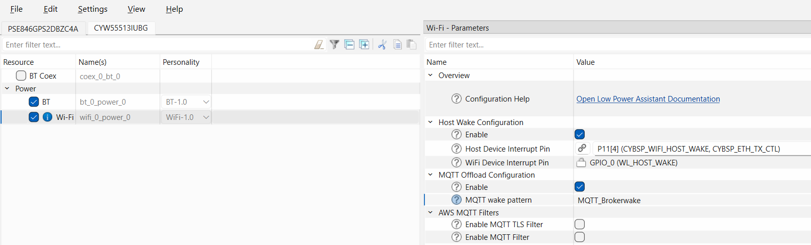
The MQTT wake pattern should be as follows:
"(topic)(wake word)"
To verify the MQTT wake pattern, send the message "wake" from the subscriber of the MQTT broker(topic); if the device wakes up, the verification is successful. Conversely, if other messages are sent, the device should remain in Sleep mode and not wake up.
Note:
Build the application and program if any changes are made in the Device Configurator.
PSOC™ Edge MCU: Bluetooth® LE CTS Client code example
This section describes power measurement in KIT_PSE84_EVAL_EPC2 with the PSOC™ Edge MCU: Bluetooth® LE CTS client code example
3
. This example allows you to measure the current in different states such as no RF activity, high-duty advertisement, low-duty advertisement, and in the connected state.
Set up the KIT_PSE84_EVAL_EPC2 kit as explained in the
Hardware setup
section. Note that this section uses the N6705B power analyzer from Keysight as a reference setup to measure power
Turn on the channels to power the PSOC™ Edge MCU and AIROC™ CYW55513 Wi-Fi & Bluetooth® combo chip from the power analyzer. You can connect the onboard KitProg to view logs in terminal software through the COM port
Follow the
README
instructions provides in the code example
3
. Build and program the code example. After programming, the application starts automatically.
Figure 40
shows the output
On bootup, the AIROC™ CYW55513 Wi-Fi & Bluetooth® combo chip will not start any RF activity. You can note the PSOC™ Edge MCU and AIROC™ CYW55513 Wi-Fi & Bluetooth® combo chip current in this state. Press the
USER_BTN1 (SW2)
to start a high-duty advertisement as shown in
Figure 41
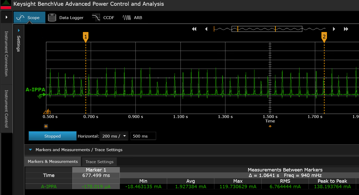
. In
Figure 42
, the green pulse represents the AIROC™ CYW55513 Wi-Fi & Bluetooth® combo chip current, when a high-duty advertisement is going on
Figure 40.
Terminal output when the device is programmed
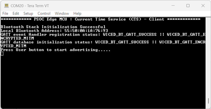
Figure 41.
Terminal output showing connection
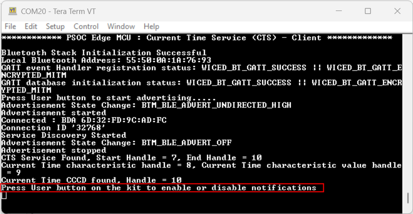
Figure 42.
Current consumption during high-duty advertisement
After 60 seconds, the device will switch to the low-duty advertisement with an interval of 1.28 seconds.
Figure 43.
Current consumption during low-duty advertisement
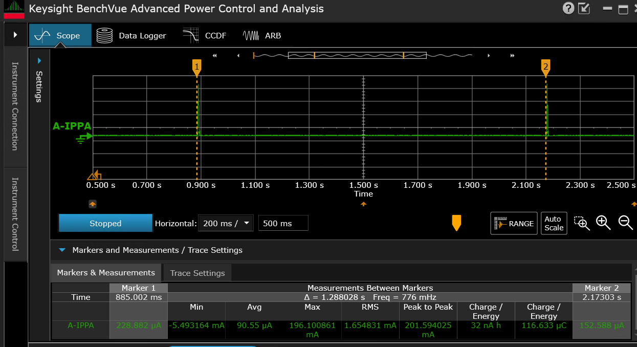
From the graph, observe that the current in the low-duty advertisement period has a higher peak. This is because the device is in Sleep mode and required to wake up for every advertisement event. However, the average current is much lower compared to the high-duty advertisement period.
Figure 44.
Current consumption with connection interval of 10 ms
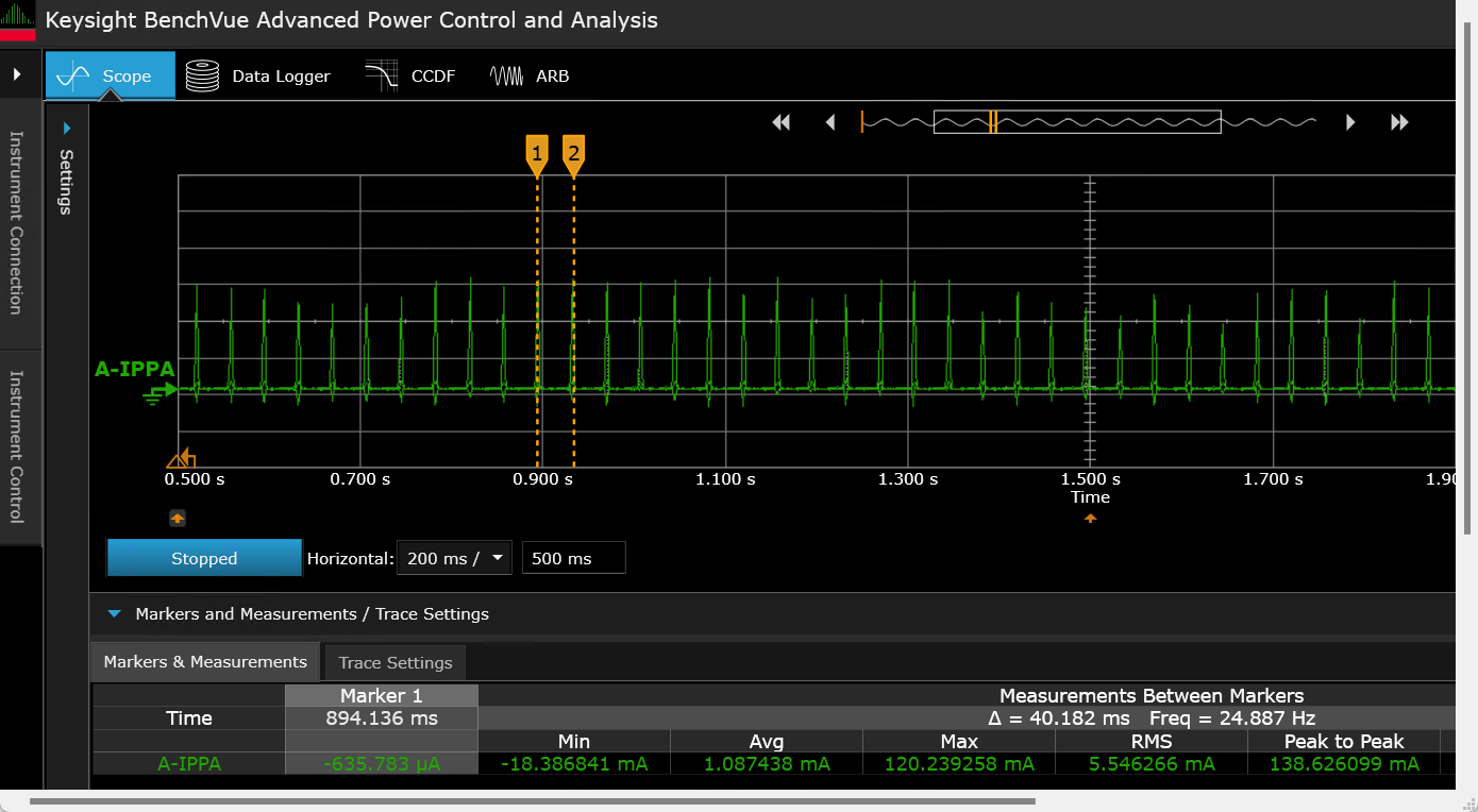
Figure 45.
Current consumption with connection interval of 50 ms
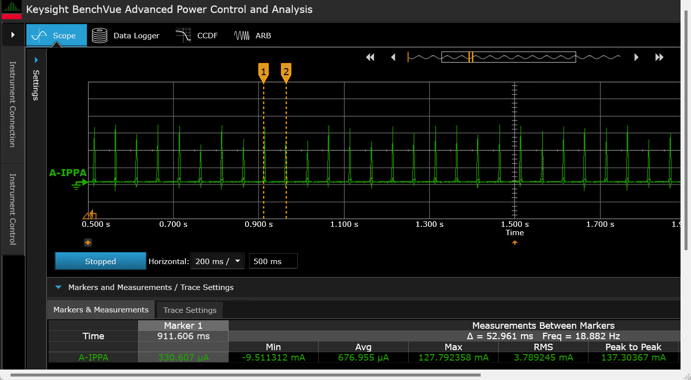
Figure 46.
Current consumption with connection interval of 500 ms
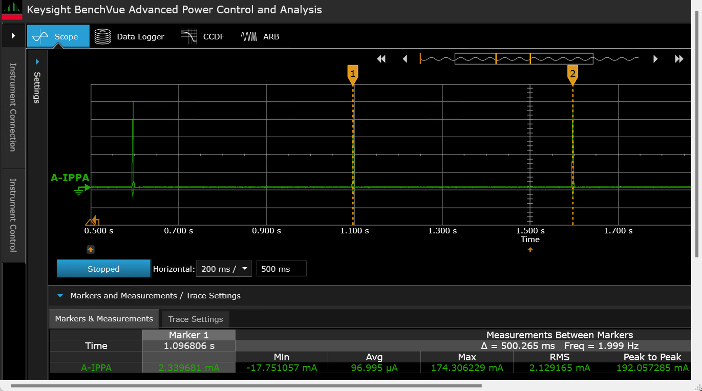
Figure 47.
Current consumption with connection interval of 1000 ms
Bluetooth® state | Setting | Device | AIROC™ CYW55513 |
|---|---|---|---|
High-duty advertisement | ADV interval: 30 ms | AIROC™ CYW55513 (VBAT) | 1.927 mA |
Low-duty advertisement | ADV interval: 1.28 s | AIROC™ CYW55513 (VBAT) | 90.55 μA |
Connected | Conn interval: 8.75 ms | AIROC™ CYW55513 (VBAT) | 2.772 mA |
Connected | Conn interval: 10 ms | AIROC™ CYW55513 (VBAT) | 1.087 mA |
Connected | Conn interval: 50 ms | AIROC™ CYW55513 (VBAT) | 676.955 μA |
Connected | Conn interval: 500 ms | AIROC™ CYW55513 (VBAT) | 96.995 μA |
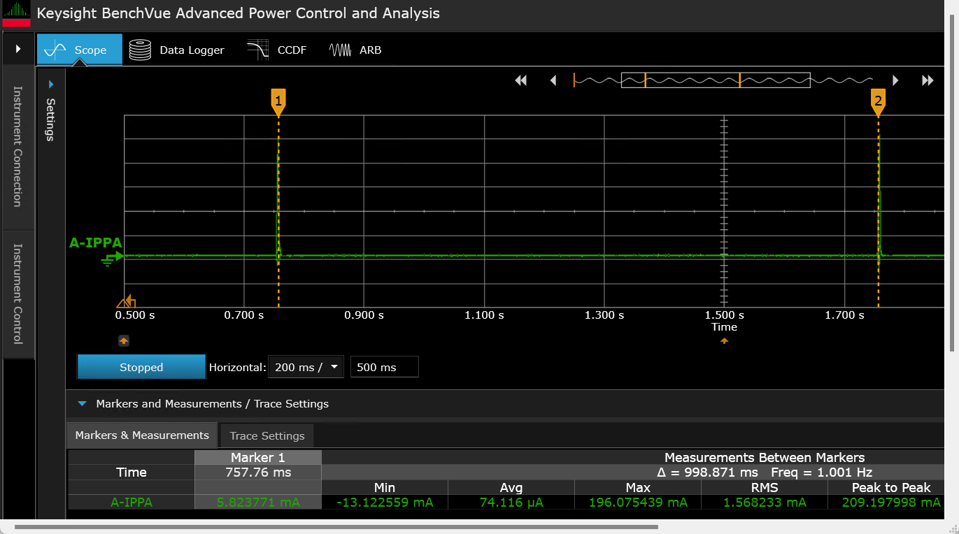
Connected | Conn interval: 1 s | AIROC™ CYW55513 (VBAT) | 74.116 μA |
PSOC™ Edge MCU: Bluetooth® LE CTS Server code example
This section describes power measurement in KIT_PSE84_EVAL_EPC2 with the PSOC™ Edge MCU: Bluetooth® Server code example
4
. This example allows you to measure the current while the device is scanning in high-duty and in low-duty.
By default, the example implements the CTS service as a GATT server.
Set up the KIT_PSE84_EVAL_EPC22 kit as explained in the
Hardware setup
section. Note that this section uses the N6705B power analyzer from Keysight as a reference setup to measure power
Turn ON the channels to power the PSOC™ Edge MCU and AIROC™CYW55513 Wi-Fi & Bluetooth® combo chip from the power analyzer. You can connect the onboard KitProg to view logs in terminal software through the COM port
Follow the
README
instructions provides in the code example
4
. Build and program the code example. After programming, the application starts automatically.
Figure 48
and
Figure 49
show the outputs respectively
On bootup, the AIROC™CYW55513 Wi-Fi & Bluetooth® combo chip will not have any RF activity
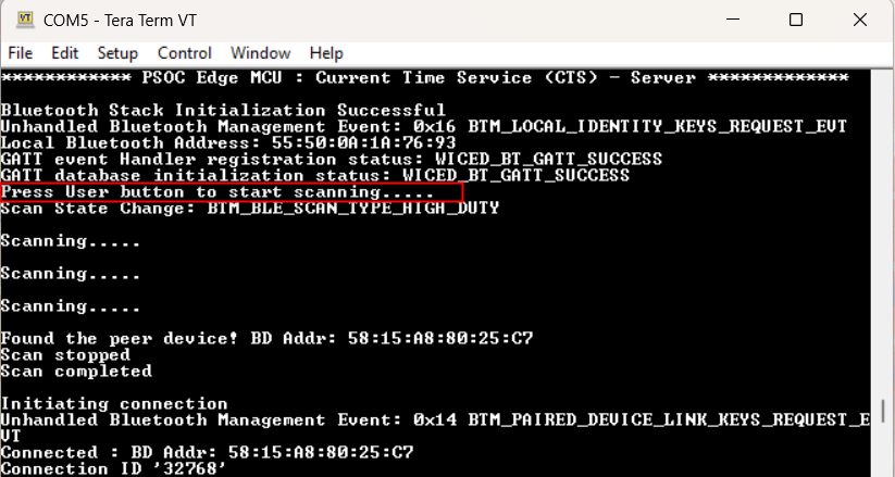
Figure 48.
Terminal output for standby mode
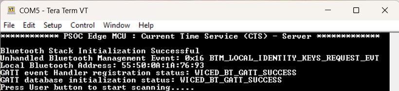
Figure 49.
Terminal output for high duty scan
Power measurement
This example enables you to measure power in three different AIROC™ Bluetooth® LE states; standby, scanning, and connected states. Follow these steps to enter each state and measure power for different kits.
To enter different states:
Standby state:
After programming the device, AIROC™ Bluetooth® LE is initialized and stays in the standby state. On the terminal, check for the message 'Bluetooth® stack initialization successful' and now you can measure power for the standby state
Scanning state:
Press the
User button (SW2)
on your kit to start scanning. Note that the kit with CTS client CE must be advertising when it starts scanning. When it discovers the peer device, it sends a connection request. A high-duty scan will be performed initially for 30 seconds. Then the device switches to low-duty scanning without a timeout. High-duty scanning of 30 seconds is chosen for faster discovery. This configuration can be changed if required using the Bluetooth® Configurator tool that comes with ModusToolbox™ installation
Connected state:
After the scanner finds the advertiser, the connection is established. The terminal displays the message 'Connected : BDA xx:xx:xx:xx:xx:xx'
Figure 50.
Current consumption during standby mode
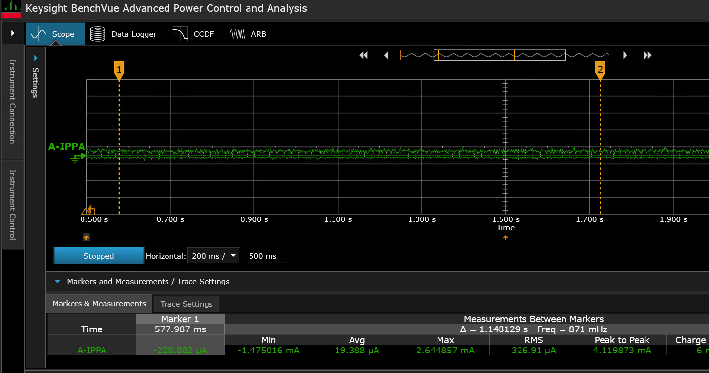
Figure 51.
Current consumption during high-duty scanning
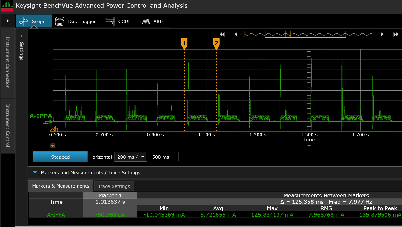
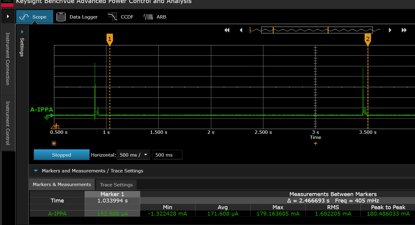
Figure 52.
Current consumption during low-duty scanning
Bluetooth® state | CYW55513IUBG |
|---|---|
Standby mode | 19.388 μA |
High duty scanning | 5.721 mA |
Low duty scanning | 171.608 μA |
Summary
The PSOC™ Edge MCU and AIROC™ CYW55513 Wi-Fi & Bluetooth® combo chip provide an industry-leading low-power IoT platform that provides many power management options. The Infineon low-power assistant middleware enables adding the low-power operation to your IoT design with ease. By following proper methods and design techniques, you can optimize your system for the lowest possible power consumption without degrading performance.
References
Webpages
Infineon Technologies AG:
PSOC™ Edge Arm® Cortex® Multicore
;
Available online
Infineon Technologies AG:
AIROC™ CYW55513 Wi-Fi & Bluetooth® combo chip
;
Available online
Application notes
Infineon Technologies AG:
AN235935 – Getting started with PSOC™ Edge E84 MCU on ModusToolbox™ software
;
Available online
Infineon Technologies AG:
AN237976 – PSOC™ Edge E84 MCU low-power modes and power reduction techniques
;
Available online
Datasheets
Infineon Technologies AG:
PSOC™ Edge E8x2, E8x3, E8x5, E8x6 datasheet
;
Available online
Infineon Technologies AG:
AIROC™ CYW55513 Wi-Fi & Bluetooth® combo chip datasheet
;
Available online
Reference manual
Infineon Technologies AG:
PSOC™ Edge E8x2, E8x3, E8x5, E8x6 reference manuals
;
Available online
Code examples on GitHub
Infineon Technologies AG:
PSOC™ Edge MCU: WLAN low-power
;
Available online
Infineon Technologies AG:
PSOC™ Edge MCU: WLAN offloads
;
Available online
Infineon Technologies AG:
PSOC™ Edge MCU: Bluetooth® LE CTS Client
;
Available online
Infineon Technologies AG:
PSOC™ Edge MCU: Bluetooth® LE CTS Server
;
Available online
Tool
Infineon Technologies AG:
ModusToolbox™ software
;
Available online
ARP
Address Resolution Protocol
ARP
BSS
Basic Service Set
CE
code example
DAD
Duplicate Address Detection
DHCP
Dynamic Host Configuration Protocol
DLTRO
DHCP Lease Time Renew offload
DNS
Domain Name System
DSP
digital signal processor
DTIM
Delivery Traffic Indication Map
DUT
Device Under Test
EDR
Enhanced Data Rate
FTP
File Transfer Protocol
FW
firmware
GPIO
general-purpose input/output
GSPI
Generic Serial Peripheral Interface
HP
High Performance
ICMP
Internet Control Message Protocol
IoT
Internet of Things
JTAG
Joint Test Action Group
LAN
Local Area Network
LNA
low-noise amplifier
LP
Low Power
LPA
low-power assistant
LPO
low-power oscillator
LR
Long Range
NA
Neighbor Advertisement
ND
Neighbor Discovery
NN
neural network
NS
Neighbor Solicitation
PA
power amplifier
PC
personal computer
PDM
pulse-density modulation
PILO
precision internal low-speed oscillator
PLL
phase-locked loop
PMU
power management unit
PPU
Power Policy Unit
RST
reset
RTC
real-time clock
SDIO
Secure-Digital Input-Output
SOM
system-on module
STA
station
TBTT
Target Beacon Transmission Time
TCP
Transfer Control Protocol
TCPKA
TCP keepalive offload
TDM
time-division multiplexing
TIM
Traffic Indication Map
U-APSD
unscheduled automatic power save delivery
UDP
User Datagram Protocol
ULP
ultra-low-power
WHD
Wi-Fi Host Driver
WOWL
Wake on Wireless LAN
Revision history
Document revision | Date | Description of changes |
|---|---|---|
** | 2025-09-17 | Initial release |
Trademarks
The Bluetooth® word mark and logos are registered trademarks owned by Bluetooth SIG, Inc., and any use of such marks by Infineon is under license.
PSOC™, formerly known as PSoC™, is a trademark of Infineon Technologies. Any references to PSoC™ in this document or others shall be deemed to refer to PSOC™.
1
The device will not enter System Deep Sleep mode until all related Power Policy Units (PPUs) are set to the correct states, as specified in
Table 2
2
See the PSOC™ Edge E84 MCU architecture reference manual for more information on Power Policy Unit (PPU)