AN235935 Getting started with PSOC™ Edge E8 MCU on ModusToolbox™ software
About this document
Scope and purpose
This application note introduces the
PSOC™ Edge
MCU, which is a dual-CPU programmable system-on-chip with Arm® Cortex® -M33 as the system processor, enabling low-power application and Arm® Cortex® -M55 as a primary application processor coupled with Arm® Ethos-U55 as a neural net co-processor.
This application note provides information on the
PSOC™ Edge
MCU architecture and development tools and shows how to create a first application using the ModusToolbox™ software. This application note also guides you to additional resources available online to accelerate the learning about
PSOC™ Edge
MCU.
Intended audience
This document is intended for the users who are new to
PSOC™ Edge
MCU and ModusToolbox™ software.
Software version
3.6 or above
Introduction
The initial sections 1 to 3 introduce the
PSOC™ Edge
MCU and its features including an introduction to software tools and resources. To quickly get started by creating a sample application, please consider going directly to section 4
First
PSOC™ Edge
MCU design using Eclipse IDE for ModusToolbox™ software
.
The
PSOC™ Edge
MCU is a programmable embedded system-on-chip having dual-CPUs. It integrates Arm® Cortex®-M33 up to 200 MHz and Arm® Cortex®-M55 up to 400 MHz coupled with an Arm® Ethos-U55 neural network coprocessor, graphics, audio block, and DSP capability. It also includes Secure Enclave having crypto accelerators and protection units. This MCU has high-performance memory expansion capability (QSPI), low-power analog subsystem with high-performance analog-to-digital conversion, low-power comparators, on-board IoT connectivity module (on SOM), communication channels, programmable analog and digital blocks allowing higher flexibility, in-field tuning of the design with faster time-to-market.
The
PSOC™ Edge
MCU is suitable for power sensitive applications including:
Smart thermostat
Smart lock
Smart home appliance
Industrial HMI
Smart Wearable
The ModusToolbox™ software environment supports the
PSOC™ Edge
MCU application development with a set of tools for configuring the device, setting up peripherals, and complementing projects with world-class middleware. See the Infineon GitHub repositories for board support packages (BSPs) for all kits and libraries along with a comprehensive array of example applications to get you started.
This application note introduces you to the capabilities of the
PSOC™ Edge
MCU, which provides an overview of the development ecosystem, and gets you started with a simple 'Hello World' application wherein you learn to use the
PSOC™ Edge
MCU. You can learn how to create the application from an empty starter application, but the completed design is available as a code example for ModusToolbox™.
Development ecosystem
PSOC™ resources
A wealth of data available here that helps you to select the right
PSOC™
MCU and quickly and effectively integrate it into your design. For more
PSOC™ Edge
MCU related documents, see the PSOC™ Edge MCU webpage .
Overview: PSOC™ Edge family
Datasheet:
002-33162: PSOC™ Edge E8x2, E8x3, E8x5, E8x6 MCU datasheet ; this document provides the device-specific electrical specifications
Reference manuals:
002-37464: PSOC™ Edge E8x2, E8x3, E8x5, E8x6 MCU architecture reference manual ; this document contains the architectural specification of different hardware blocks present in the MCU
002-37465: PSOC™ Edge E8x2, E8x3, E8x5, E8x6 MCU registers reference manual ; this document contains the register list and bit-filed description of all the hardware blocks present in the MCU
Application notes:
- AN235935: Getting started with PSOC™ Edge MCU on ModusToolbox™
- AN236517: PCB layout guidelines for PSOC™ Edge MCU
- AN237976: PSOC™ Edge MCU low-power modes and power reduction techniques
- AN238090: Connecting to Cloud Services using ModusToolbox™
- AN237849: Getting started with PSOC™ Edge security
- AN236697: Getting started with PSOC™ Edge MCU and AIROC™ connectivity devices
- AN239191: Getting started with graphics on PSOC™ Edge MCU
- AN239774: Selecting and configuring memories for power and performance in PSOC™ Edge MCU
- AN239757: Authenticated Debug for PSOC™ Edge
Code examples: Numerous example applications featuring various peripheral and system middlewares
Development kit resources
002-38793: Quick start guide
002-39007: User guide
Kit schematic and layout files
630-60647-01: Baseboard schematic
630-60673-01: SOM schematic
PSOC™ Edge resources:
Training videos: Video training on products and tools
Technical support: PSOC™ developer community forum , Knowledge base articles
Firmware/application development
ModusToolbox™ software
The ModusToolbox™ software is a modern, extensible development environment supporting a wide range of Infineon microcontroller devices. It provides a flexible set of tools and a diverse, high-quality collection of application-focused software. These include configuration tools, low-level drivers, libraries, and operating system support, most of which are compatible with Linux-, macOS-, and Windows-hosted environments.
Software resources available at GitHub support one or more of the target ecosystems:
MCU and Bluetooth® SoC ecosystem: A full-featured platform for PSOC™ MCU, Bluetooth®, and Bluetooth® low-energy application development
Connectivity ecosystem: A set of libraries providing core functionality of Wi-Fi, including connectivity, security, firmware upgrade support, and application layer protocols for applications
Amazon FreeRTOS ecosystem: Extends the FreeRTOS kernel with software libraries that make it easy to securely connect small, low-power Infineon devices to most cloud services
ModusToolbox™ tools and resources can also be used on the command line. For more details, see the build system chapter in the
ModusToolbox™ tools package user guide
.
Installing ModusToolbox™ tools package
The ModusToolbox™ tools package can be installed using any of the below methods:
ModusToolbox™ Setup program
: It is highly recommended to use the ModusToolbox™ Setup program for a simplified installation experience. You can download and use the ModusToolbox™ Setup program from
Infineon Development Center
to install the tools package, as well as many other packages such as early access packs, Programming tools, etc. Refer to the
Setup program user guide
for more details
Standalone installation
: The user may also download just the ModusToolbox™ tools package from the
Infineon Development Center
for offline installation. For more details, see the
ModusToolbox™ tools package installation guide
After installing the software, see the
ModusToolbox™ tools package user guide
to get an overview of the software.
Choosing an IDE
The ModusToolbox™ software is supported across Windows, Linux, and macOS platforms. The ModusToolbox™ software supports third-party IDEs, including the Eclipse IDE, Visual Studio Code, Arm® MDK (μVision), and IAR Embedded Workbench. The tools package includes an implementation for the Eclipse IDE for convenience. The associated BSP and library configurators also work on all three host operating systems.
Beginning with the ModusToolbox™ tools package version 3.4.0, the Eclipse IDE for ModusToolbox™ is no longer included by default. Instead, it is a separate package that you can install via the ModusToolbox™ Setup program.
You can develop firmware for the
PSOC™
Edge MCU using any one of the following IDEs: Eclipse, IAR Embedded Workbench, Keil μVision 5, or Visual Studio Code. This application note uses Eclipse IDE for demonstration purpose.
See the following documents to learn how to use ModusToolbox™ with the different IDEs:
Software features
The ModusToolbox™ tools package installer includes the design configurators and tools and the build system infrastructure.
The build system infrastructure includes the new project creation wizard that can execute independent of the Eclipse IDE, the make infrastructure, and other tools. This means you can choose your compiler, IDE, RTOS, and ecosystem without compromising usability or access to our wide portfolio of middleware assets, which include HMI, machine learning, Wi-Fi, Bluetooth®, security, and various other features.
Design configurators are the tools that help you create the configurable code for required BSP or middleware. For more details, see the
Configurators
section.
Figure 1.
ModusToolbox™ software stack
shows a high-level view of the application capabilities of Infineon devices using the ModusToolbox™ software. For more details on the overview of the ModusToolbox™ software, see the
ModusToolbox™ tools package user guide
.
All the application-level development flows depend on the low-level resources provided. These include the following:
Libraries/middleware (MW): Extensive middleware libraries that provide specific capabilities to an application. The available middleware spans across connectivity (OTA, Bluetooth®, AWS IoT, Bluetooth® LE, Secure Sockets to
PSOC™
MCU-specific functionality (USB, device firmware upgrade (DFU), and emWin). All the middleware is delivered as libraries via GitHub repositories
Board Support Packages (BSP): A BSP is the layer of firmware containing board-specific drivers and other functions. The BSP is a set of libraries that provide APIs to initialize the board and provide access to board-level peripherals. It includes low-level resources such as the Peripheral Driver Library (PDL) for the
PSOC™
MCU and macros for board peripherals. Custom BSPs can be created to enable support for end-application boards. See BSP Assistant to create your BSP
Device Support Library (DSL): A device support library combines content from several distinct software packages into a single package which includes the following major assets:
PSOC™
MCU Peripheral Driver Library (PDL): The PDL integrates device header files, start-up code, and peripheral drivers into a single package. The PDL supports the
PSOC™
MCU family. The drivers abstract the hardware functions into a set of easy-to-use APIs. These are fully documented in the PDL API Reference.
The PDL reduces the need to understand register usage and bit structures, therefore easing software development for the extensive set of peripherals in the
PSOC™
MCU series. Configure the driver for the application and then call APIs to initialize and use the peripheral
Hardware Abstraction Layer (HAL): The HAL provides a high-level interface to configure and use hardware blocks on MCUs. It is a generic interface that can be used across multiple product families. The focus on ease-of-use and portability means the HAL does not expose all the low-level peripheral functionality. The HAL wraps the lower-level drivers (such as
PSOC™
MCU PDL) and middlewares to provides a high-level interface to the MCU. The interface is abstracted to work on any MCU. This helps you write the application firmware independent of the target MCU
Device Utilities (device-utils): This asset handles the pre-defined System Power Management (SysPm) callback implementations for peripherals which require special handling when the MCU enters or exits DeepSleep
Configurators:ModusToolbox™ Configurators are stand-alone tools that can be used to set up and configure
PSOC™
Edge MCU resources and other middleware components without using the Eclipse IDE. The Device configurators and middleware configurators use the
design.x
files within the application workspace. You can then point to the generated source code and continue developing firmware in your IDE.
If there is a change in the device configuration, edit the
design.x
files using the configurators and regenerate the code. It is recommended that you generate resource configurations using the configuration tool provided with ModusToolbox™ software.
For more details on configurators, see the
Configurators
section
Application structure
The ModusToolbox™ v3.x release supports multi-core functionality. All applications for the
PSOC™ Edge
MCU will have a dual-core three project structure. The applications have app-owned BSPs, meaning the BSP will be common to all projects inside a multi-core application.
The folder structure of a typical code example application is illustrated below.
              ├───mtb-example-app
              │   │   common.mk
              │   │   common_app.mk
              │   │   Makefile (MTB_TYPE = APPLICATION)
              │   │
              │   ├───bsps
              │   │   └───TARGET_BSP1 (app-owned BSP)
              │   │
              │   ├───images
              │   │
              │   ├───proj_cm33_s (First Project)
              │   │   │   main.c
              │   │   │   Makefile (MTB_TYPE = PROJECT)
              │   │   │   project1_helper.c
              │   │   │   project1_helper.h
              │   │   │
              │   │   ├───deps
              │   │   │       lib1.mtb (Local)
              │   │   │       lib2.mtb (Shared)
              │   │   │
              │   │   └───libs
              │   │           lib1 (Infineon Git repo)
              │   │
              │   ├───proj_cm33_ns (Second Project)
              │   │
              │   ├───proj_cm55 (Third Project)
              │   │
              │   └───templates
              │       └───TARGET_BSP1
              │           └───config
              │                   design.modus
              │
              └───mtb-shared
                  └───lib2 (Infineon Git repo)
PSOC™ Edge software resources
The software for the
PSOC™ Edge
MCU includes configurators, drivers, libraries, and middleware, as well as various utilities, makefiles, and scripts. It also includes relevant drivers, middleware, examples for use with IoT devices, and connectivity solutions. You may use any or all tools in any environment that you prefer. The following sections provide detailed information about these software resources.
Configurators
The ModusToolbox™ software provides graphical applications called configurators that make it easier to configure a hardware block. For example, instead of having to search through all the documentation to configure a serial communication block as a UART with a desired configuration, open the device configurator and set the baud rate, parity, and stop bits. Upon saving the hardware configuration, the tool generates the "C" code to initialize the hardware with the desired configuration.
Two types of configurators are:
BSP configurators that configure items that are specific to the MCU hardware
Library configurators that configure options for middleware libraries
Configurators are independent of each other, but they can be used together to provide flexible configuration options. They can be used stand-alone, in conjunction with other tools, or within a complete IDE. Configurators are used for:
Setting options and generating code to configure drivers
Setting up connections such as pins and clocks for a peripheral
Setting options and generating code to configure middleware
For the
PSOC™ Edge
MCU applications, the available configurators include the following:
Device Configurator: Set up the system (platform) functions, pins, and the basic peripherals (e.g., UART, Timer, and PWM)
ML Configurator: To fit the pre-trained model of choice to the target device with a set of optimization parameters (only available as a part of a separate pack)
QSPI Configurator: Configure an external memory and generate the required code
Smart I/O Configurator: Configure smart I/O pins
Bluetooth® Configurator: Configure the Bluetooth® settings
Each of the above configurators creates their own design files. BSP configurator file (e.g.,
design.modus
) are provided as part of the BSP with default configurations, while library configurators (e.g.,
design.cybt
) are provided by the application. When an application is created based on Infineon BSP, the application makes use of BSP configurator files from the Infineon BSP repository. You can customize or create all the configurator files as per the application requirements using the ModusToolbox™ software. To create a custom BSP, see
BSP Assistant
. For more details, see the
ModusToolbox™ help
section.
Library management for PSOC™ Edge MCU
The application can have shared or local libraries for the projects. If needed, different projects can use different versions of the same library. The shared libraries are downloaded in the mtb_shared directory. The application should use the
deps
folder to add library dependencies. The
deps
folder contains files with the
.mtb
file extension, which is used by ModusToolbox™ to download its git repository. These libraries are direct dependencies of the ModusToolbox™ project.
The Library Manager helps to add, remove, or update the libraries of your projects. It also identifies whether the particular library has a direct dependency on any other library using the manifest repository available on GitHub and fetches all the dependencies of that particular library. These dependency libraries are indirect dependencies of the ModusToolbox™ project. These dependencies can be seen in the
libs
folder. For more information, see the
Library Manager user guide
located at
<install_dir>/ModusToolbox/tools_<version>/library-manager/docs/library-manager.pdf
.
Software development for PSOC™ Edge MCU
The ModusToolbox™ ecosystem provides significant source code and tools to enable software development for PSOC™ Edge MCUs. You can use tools to:
Specify how you want to configure the hardware
Generate code that you can use in the firmware
Include various middleware libraries for additional functionality, such as emUSB or FreeRTOS
This source code makes it easier to develop the firmware for supported devices. It helps you quickly customize and build firmware without needing to understand the register set.
In the ModusToolbox™ environment, you can use configurators to configure either the device or a middleware library, such as the Bluetooth® LE stack. The BSP configurator files are used to configure device peripherals, pins, and memory using peripheral driver library code. The middleware is delivered as separate libraries for each feature or function so that it can be used across multiple platforms. For example, abstraction-rtos, lwIP, USB, and so on.
Firmware developers who wish to work at the register level should refer to the driver source code from the PDL. The PDL includes all the device-specific header files and startup code you need for the project. It also serves as a reference for each driver. Because the PDL is provided as source code, you can see how it accesses the hardware at the register level.
Some devices do not support particular peripherals. The PDL is a superset of all the drivers for any supported device. This superset design means:
All API elements needed to initialize, configure, and use a peripheral are available
The PDL is useful across various PSOC™ Edge MCUs, regardless of available peripherals
The PDL includes error checking to ensure that the targeted peripheral is present on the selected device
This enables the code to maintain compatibility across members of the
PSOC™ Edge
MCU family, as long as the peripherals are available. A device header file specifies the peripherals that are available for a device. If you write code that attempts to use an unsupported peripheral, you will get an error at compile time. Before writing code to use a peripheral, consult the datasheet for the particular device to confirm support for that peripheral.
As
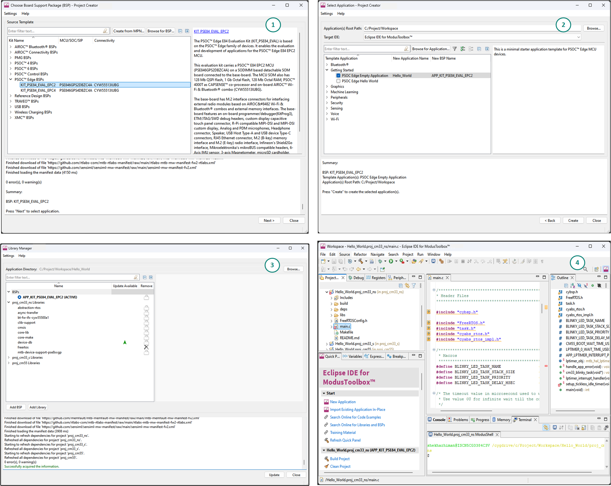
Figure 2
shows, with the ModusToolbox™ software, you can do the following:
Choose a BSP (Project Creator)
Create a new application based on a list of starter applications, filtered by the BSPs that each application supports (Project Creator)
Add BSP or middleware libraries (Library Manager)
Develop the application firmware for the
PSOC™ Edge
MCU (IDE of choice or command line)
Figure 2.
ModusToolbox™ resources and middleware
ModusToolbox™ help
The ModusToolbox™ ecosystem provides documentation and training. One way to access it is launching the Eclipse IDE for ModusToolbox™ software and navigating to the following
Help
menu items:
Choose
Help
>
ModusToolbox™ General Documentation
:
ModusToolbox™ Documentation Index:
Provides brief descriptions and links to various types of documentation included as part the ModusToolbox™ software
ModusToolbox™ Installation Guide:
Provides instructions for installing the ModusToolbox™ software
ModusToolbox™ User Guide:
This guide primarily covers the ModusToolbox™ aspects of building, programming and debugging applications. It also covers various aspects of the tools installed along with the IDE
ModusToolbox™ Training Class Material:
For the training material, see the ModusToolbox™ Software Training webpage.
Release Notes
For documentation on Eclipse IDE for ModusToolbox™, choose
Help
>
Eclipse IDE for ModusToolbox™ General Documentation
:
Quick Start Guide:
Provides you the basics for using Eclipse IDE for ModusToolbox™
User Guide:
Provides descriptions about creating applications as well as building, programming, and debugging them using Eclipse IDE
Eclipse IDE for ModusToolbox™ Help:
Provides description on how to create new applications, update application code, change middleware settings, and program/debug applications
Eclipse IDE Survival Guide
FreeRTOS support with ModusToolbox™
Adding native FreeRTOS support to a ModusToolbox™ application project is like adding any middleware library. You can include the FreeRTOS middleware in your application by using the Library Manager.
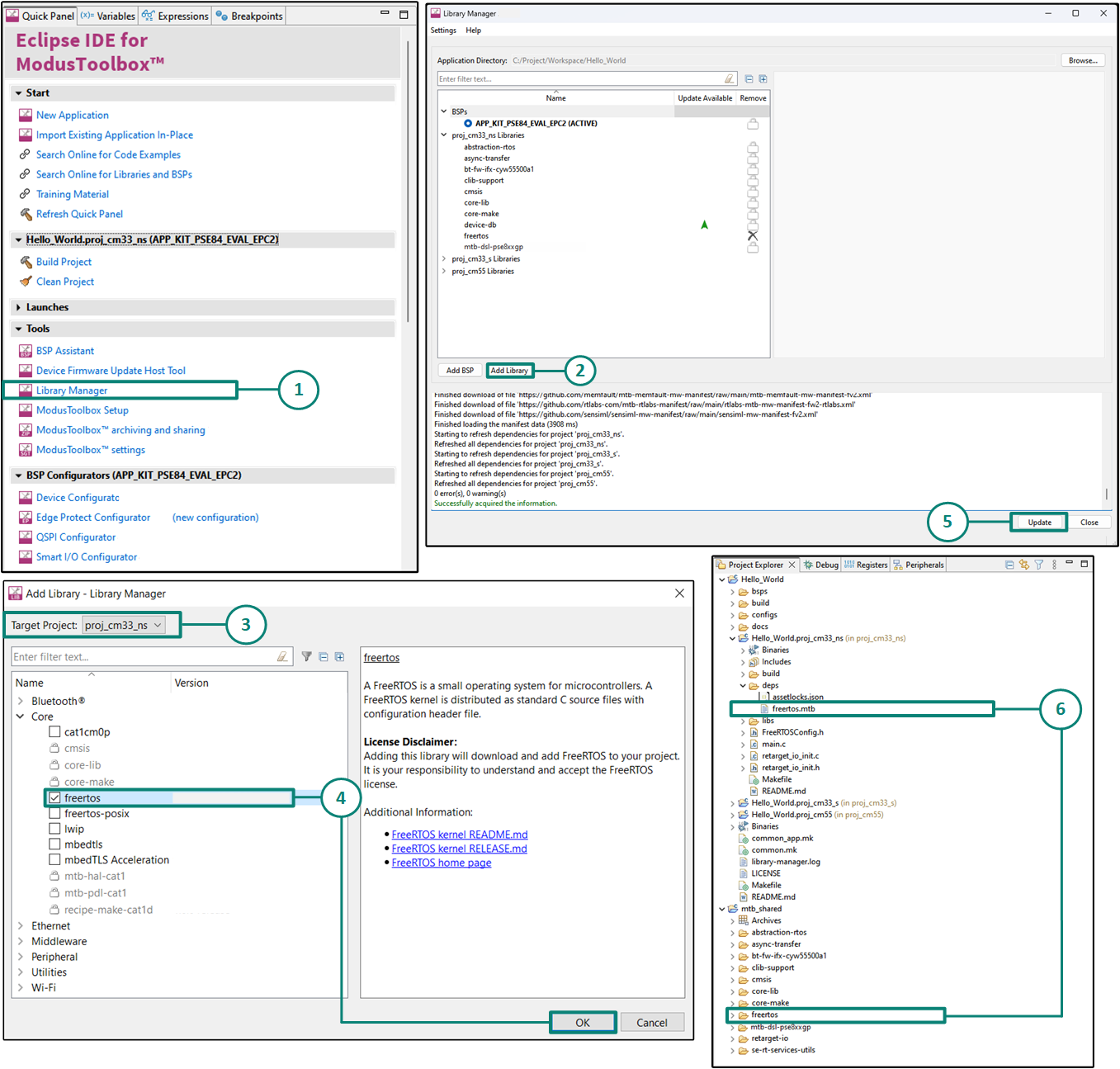
If using the Eclipse IDE, do the following as marked in
Figure 3
:
Open
Library Manager
from the Quick Panel.
Select
"Add Library"
in the Library manager.
Select the project
to add the FreeRTOS middleware.
Select
FreeRTOS library
that is present in the "core" tab. Click
OK
to close the "Add Library" dialog.
Click
"Update"
in Library Manager to fetch the FreeRTOS library.
The
freertos.mtb
file pointing to the FreeRTOS middleware is added to the application project's deps directory. The middleware content is also downloaded and placed inside the corresponding
freertos
folder. The default location is in the shared asset
mtb_shared
repository.
Figure 3.
Import FreeRTOS middleware in ModusToolbox™ application
To continue working with FreeRTOS, follow the steps mentioned in the Quick Start section of
FreeRTOS documentation
.
Programming and Debugging
The ModusToolbox™ software supports the
Open On-Chip Debugger
(OpenOCD) using a GDB server and supports the J-Link debug probe.
You can use various IDEs to program devices and establish a debug session (see
Choosing an IDE
). For programming, the
PSOC™ Programmer
is available separately. It is a cross-platform application for programming Infineon microcontroller devices. It can program, erase, verify, and read the flash of the target device.
The
PSOC™ Edge
MCU has a KitProg3 onboard programmer and debugger. It supports the Cortex® microcontroller Software Interface Standard - Debug Access Port (CMSIS-DAP). For more details, see the
KitProg3 user guide
.
ModusToolbox™ requires KitProg3 or an external programmer which then uses the OpenOCD protocol for debugging the
PSOC™ Edge
MCU applications. It also supports GDB debugging using industry-standard probes such as the Segger J-Link.
For more information on debugging firmware on the
PSOC™ Edge
MCU with ModusToolbox™, see the Program and Debug section in the
Eclipse IDE for ModusToolbox™ user guide
.
PSOC™ Edge MCU development kit
This application note uses the
PSOC™
Edge E84 Evaluation Kit for developing and programming the application on the MCU. There are two categories of parts in this family, the Edge Protect Category 2 (EPC 2) and the Edge Protect Category 4 (EPC 4) parts. These parts are compliant to the Edge Protect categories 2 and 4 as described
here
. Each part is supported by its dedicated Board Support Package (BSP). For further details on the distinction and comparison between the two Edge Protect Categories, refer to
AN237849 - Getting Started with the
PSOC™
Edge Security
document.
For the purposes of this document, we will use the Board Support Package (BSP) with the EPC 2 part (KIT_PSE84_EVAL_EPC2).
The evaluation kit carries a
PSOC™
Edge E84 MCU on a SODIMM-based detachable SOM board connected to the baseboard. The MCU SOM also has 128 Mb of QSPI flash, 1Gb of Octal flash, 128 Mb of Octal RAM,
PSOC™
4000T as the CAPSENSE™ co-processor, and an on-board AIROC™ Wi-Fi & Bluetooth ®combo.
The baseboard has the following:
M.2 interface connectors for interfacing external radio modules based on AIROC™ Wi-Fi & Bluetooth ® combos and external memory interfaces
An on-board programmer and debugger (KitProg3)
ETM/JTAG/SWD debug headers
Custom display capacitive touch panel connector
R-Pi-compatible MIPI-DSI and MIPI-DSI custom display
Analog and PDM microphones
Headphone connector and a speaker
USB host type-A and USB device type-C connectors
RJ45 Ethernet connector
M.2 (B-key) memory interface and M.2 (E-key) radio interface
Infineon’s Shield2Go interface and Mikroelektronika's mikroBUS compatible headers
6-Axis IMU sensor and 3-axis magnetometer
microSD cardholder
CAPSENSE™ buttons and slider
User LEDs and buttons
For more details, see the
PSOC™
Edge E84 Evaluation Kit user guide.
Device features
The
PSOC™
Edge product line has extensive features as shown in
Figure 4
. For more information, see the device datasheet, the reference manual, and the
References
section. The following are the major features:
Always-on domain
Acoustic activity detection
ADC, operational amplifiers, comparator, and DACs
Autonomous Analog
2x Continuous-Time Blocks (CTB) offering Analog Front-End (AFE) functions such as:
Programmable Gain Amplifier (PGA)
Transimpedance Amplifier (TIA)
Pseudo-Differential Amplifier
Comparator
SAR ADC with
5 Msps sample rate at 12 bits or 250 ksps at 16 bits in System High Performance mode
200 ksps sample rate at 12 bits or 12.5 ksps at 16 bits in System Deep-Sleep mode
Accumulation and averaging – 2x, 4x, 8x … 256x
Limit detection, Offset and gain calibration
2x 12-bit DAC with 1 μS refresh time, automatic waveform generation
2x Programmable Threshold Comparators (PTComp) with post-processing supporting Audio Activity Detection (AAD) and Motor Control
Autonomous Controller capable of performing following functions in Device DeepSleep Mode
Power cycling of individual blocks
Send triggers and/or interrupts to the CPU
Digital output to as many as four GPIOs
Security features
Lockstep secure enclave in low‑power always‑on domain
Secure Infineon RoT key storage; secure boot
Tamper detection, side channel attack (SCA) mitigation, and protection against fault injection attacks
Secure enclave runtime services for Arm® Platform Security Architecture (PSA) compliant cryptography, key management, secure storage and attestation services; available on EPC 4 part numbers only. (See device datasheet)
Up to Infineon Edge Protect Category 4 (EPC 4), depending on part number. (See device datasheet)
Off‑the‑shelf Trusted Firmware‑M enablement and Mbed‑TLS for crypto operations
Secure isolation of processing environments via Arm® TrustZone with root-of-trust established at boot by Cortex®‑M33 CPU
Factory-provisioned device unique keypair (DICE_DeviceID), Hardware Unique Key (HUK), Unique DeviceSecret (UDS) and Infineon device certificates
Infineon proprietary protection units for memory and peripherals
Secure firmware update; secure debug, secure RMA mode for field failure analysis
Low‑power security, control, and communication CPU
Cortex®‑M33 with FPU, DSP, and MPU up to 200 MHz in System High Performance (HP) power mode. (See device datasheet for power modes)
16 KB I‑cache
RRAM module for NVM
DMA
Hardware crypto accelerator with comprehensive support of cryptographic algorithms
High-performance compute, DSP, and machine learning (ML) blocks
Cortex®‑M55 CPU with DSP extension at 400 MHz in System High Performance (HP) power mode
FPU, MVE extension with vectored fixed and floating point
32‑KB I‑cache and 32‑KB D‑cache
256‑KB I- and 256‑KB D‑TCMs
Ethos‑U55 NN coprocessor with 128 multiply-accumulate operations (MACs) per cycle; 51.2 billion operations per second
HPDMA
Multi‑AXI high‑bandwidth interconnect
Communications and connectivity
HS USB host/device, 480 Mbps
SD host controllers with eMMC mode
Serial memory interfaces (SMIF) with octal DDR
Ethernet 10/100 media access control (MAC)
CAN FD
I3C bus for 2‑wire sensor hubs
I2C, SPI, and UART via serial communication blocks (SCB)
HMI functional blocks
2.5D graphics processor for rendering images and text
Display controller with MIPI DSI
Audio multi‑microphone interface for far-field applications
Optimizable power
Independent voltage domains allowing selectable domain power for low-power or high-performance (See device datasheet)
Active, sleep, deep sleep, and hibernate modes
On‑chip DC‑DC buck converter
Dynamic voltage and frequency scaling, for real‑time power optimization
Granular SRAM blocks for selectable SRAM retention
Programmable GPIO pins
Programmable drive modes, strengths, and slew rates
Overvoltage tolerant (OVT) pins for I2C compliance
ModusToolbox™ design environment
Code development and debugging in a cross-OS (Windows, Linux, Mac OS) IDE-neutral environment supporting Visual Studio Code, IAR, Keil and Eclipse IDEs
Installable software development kits (SDK) for peripheral initialization, clock and pin configuration, and middleware selection
Peripheral driver library (PDL) for peripheral APIs, including SD host controller for connection to IoT devices; and ML library
Industry-standard CMSIS pack support
RTOS support, including FreeRTOS
DEEPCRAFT™ Studio enabling the full journey from ML model development to embedded software
Figure 4.
PSOC™ Edge
MCU block diagram
First PSOC™ Edge MCU design using Eclipse IDE for ModusToolbox™ software
This section describes the following:
How to build a simple PSOC™ Edge MCU-based design and program it onto the development kit
Makes it easy to learn PSOC™ Edge MCU design techniques and how to use the ModusToolbox™ software and Eclipse IDE
Prerequisites
Before you get started, make sure that you have the appropriate development kit for the
PSOC™ Edge
MCU product line, and have installed the required software. You also need internet access to the GitHub repositories during project creation.
Hardware prerequisites
The following design example is developed for the
PSOC™
Edge E84 Evaluation kit with the Edge Protect Category 2 (EPC 2) part (KIT_PSE84_EVAL_EPC2). However, you can build the application for other development kits including the Edge Protect Category 4 (EPC 4) part (KIT_PSE84_EVAL_EPC4). For more details, see the
Application development instructions
section.
For the design example shown in this application note, the minimum required revision for the
PSOC™
Edge E84 Evaluation kit is Rev *G.
For the provisioning flow, the minimum version of KitProg3 firmware required on
PSOC™
Edge E84 Evaluation kit is
2.60.1412
. Please see
Program the device
section for steps to upgrade the KitProg3 firmware.
On the
PSOC™
Edge E84 Evaluation kit please ensure below jumper and pin configuration are correctly placed on board.
Ensure
Boot SW
should be in 'High'/ON position
Ensure
J20
and
J21
should be in Tristate/Not-Connected(NC) position
Software prerequisites
Following are the software prerequisites
ModusToolbox™ software v3.6 or above.
See Installing ModusToolbox™ tools package for detailed installation instructions
ModusToolbox™ Edge Protect Security Suite v1.6.0 or above
ModusToolbox™ Programming Tools v1.5.0 or above
Arm® GNU Toolchain(GCC) v14.2.1
If you install the ModusToolbox™ tools package using the ModusToolbox™ Setup program, the Edge Protect Security Suite, Programming Tools and GCC Toolchain are installed automatically as required dependencies. If you instead get the tools package from the Infineon Developer Center, you must download and install these dependencies manually.
Application development instructions
The following sections provide guidelines on how to develop an application:
Create a new application
View and modify the design
Write firmware
Build the application
Program the device
Test your design
This design is developed for the
PSOC™
Edge E84 Evaluation Kit (KIT_PSE84_EVAL_EPC2).
About the design
This design uses the Arm® Cortex® M33 core of the
PSOC™ Edge
MCU to execute the following two tasks: UART communication and LED control.
At device reset, the secure boot process starts from the ROM boot with the secure enclave (SE) as the root of trust (RoT). It passes through a series of immutable boot codes and starts the CM33 secure application. This application needs to be in MCUboot format. The ModusToolbox™ build process supports the converting of the user image into MCUboot format using the combiner-signer feature of EdgeProtectTools.
The CM33 secure application performs the TrustZone configurations and launches the non secure application running on the same CM33 core.
The non-secure CM33 application is started and then proceeds to initialize the board peripherals and other resources. It enables the CM55 core and the project for CM55 core puts it to deepsleep. The CM33 non-secure application uses the UART to print a “Hello World” message to the serial port stream, and starts blinking the user LED on the kit.
Create a new application
This section provides a step-by-step guideline for creating a new application. It uses the
Empty App
starter application and manually adds the functionality from the
Hello World
starter application. The Eclipse IDE for ModusToolbox™ is used in the instructions, but you can use any IDE or the command line if you prefer.
If you are familiar with developing projects with ModusToolbox™ software, you can use the
Hello World
starter application directly. It is a complete design, with all the firmware written for the supported kits. You can walk through the instructions and observe how the steps are implemented in the code example.
If you start from scratch and follow all the instructions in this application note, you can use the
Hello World
code example as a reference while following the instructions.
Launch the
Dashboard
application to get started. Note that the
Dashboard
application needs access to the internet to successfully clone the starter application onto your machine.
The
Dashboard
application helps you get started using the various tools with easy access to documentation and training material, a simple path for creating applications, and creating and editing BSPs.
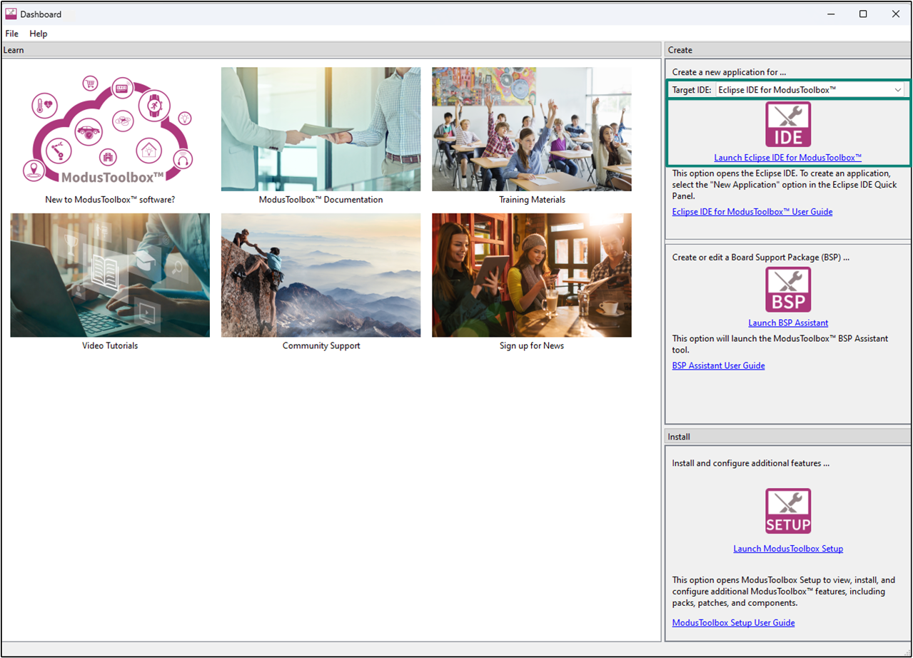
Do the following to create a new application:
Open the Dashboard application by clicking on
[ModusToolbox installation path]/tools_X.X/dashboard/dashboard.exe
In the right pane of the
Dashboard
window, select
Eclipse IDE for ModusToolbox™
in the
Target IDE
drop-down list and click
Launch Eclipse IDE for ModusToolbox™
Figure 5.
Dashboard application
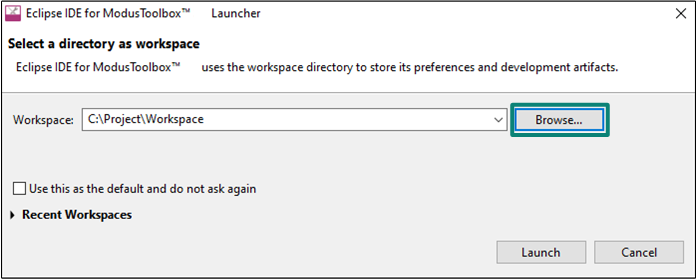
Select a new workspace
At launch, Eclipse IDE for ModusToolbox™ presents a dialog to choose a directory to use as the workspace directory. The workspace directory is used to store workspace preferences and development artifacts. You can choose an existing empty directory by clicking the Browse button, as shown in the following
Figure 6
. Alternatively, you can type in a directory name to be used as the workspace directory along with the complete path, and the Eclipse IDE will create the directory for you.
Figure 6.
Select a directory as the workspace
Create a new ModusToolbox™ application
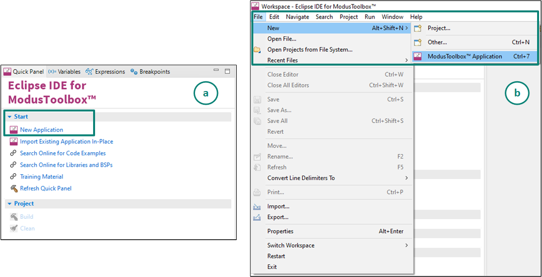
From the Quick Panel, Click on
Start
, and then click
New Application
Alternatively, you can choose
File > New > ModusToolbox™ Application
, as shown in
Figure 7
The Project Creator opens.
Figure 7.
Create a new ModusToolbox™ application
Select a target
PSOC™
development kit.
ModusToolbox™ speeds up the development process by providing BSPs that set various workspace project options for the specified development kit in the new application dialog
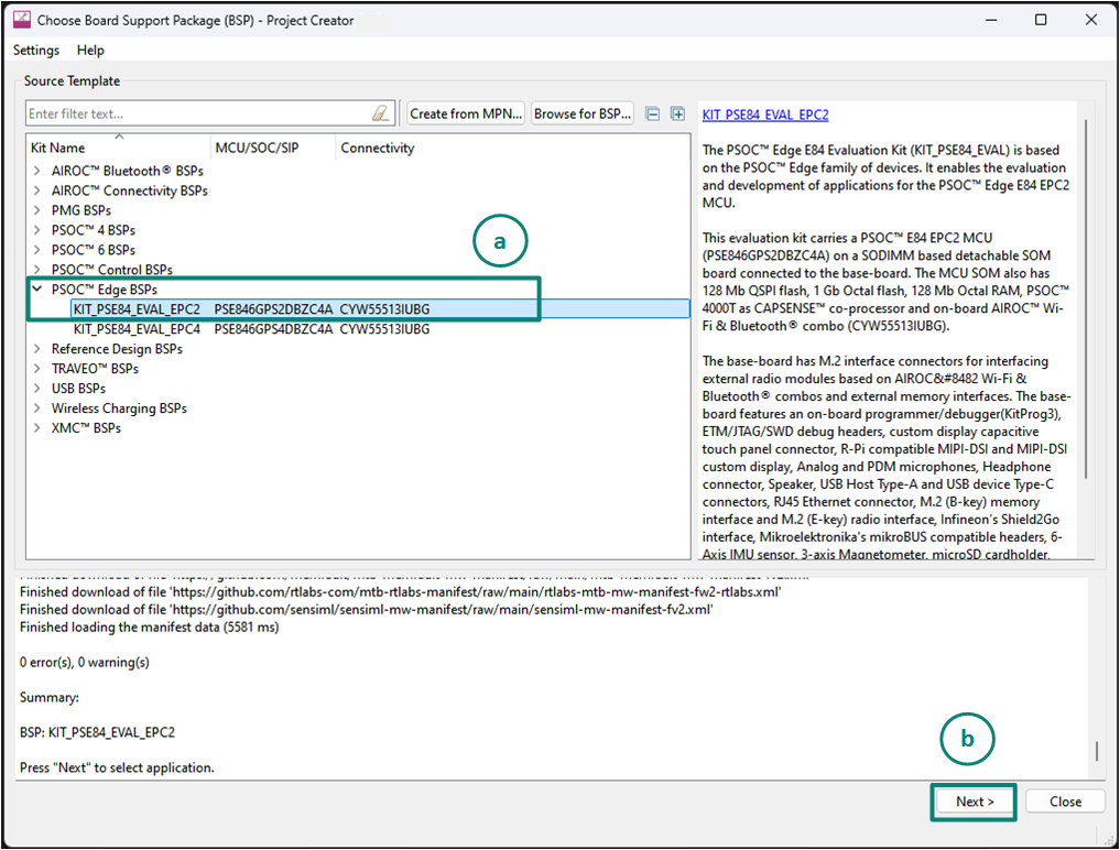
In the
Choose Board Support Package (BSP)
dialog, choose the
Kit Name
. For example, choose
KIT_PSE84_EVAL_EPC2
, as shown in
Figure 8
Click
Next
.
Figure 8.
Choose target hardware
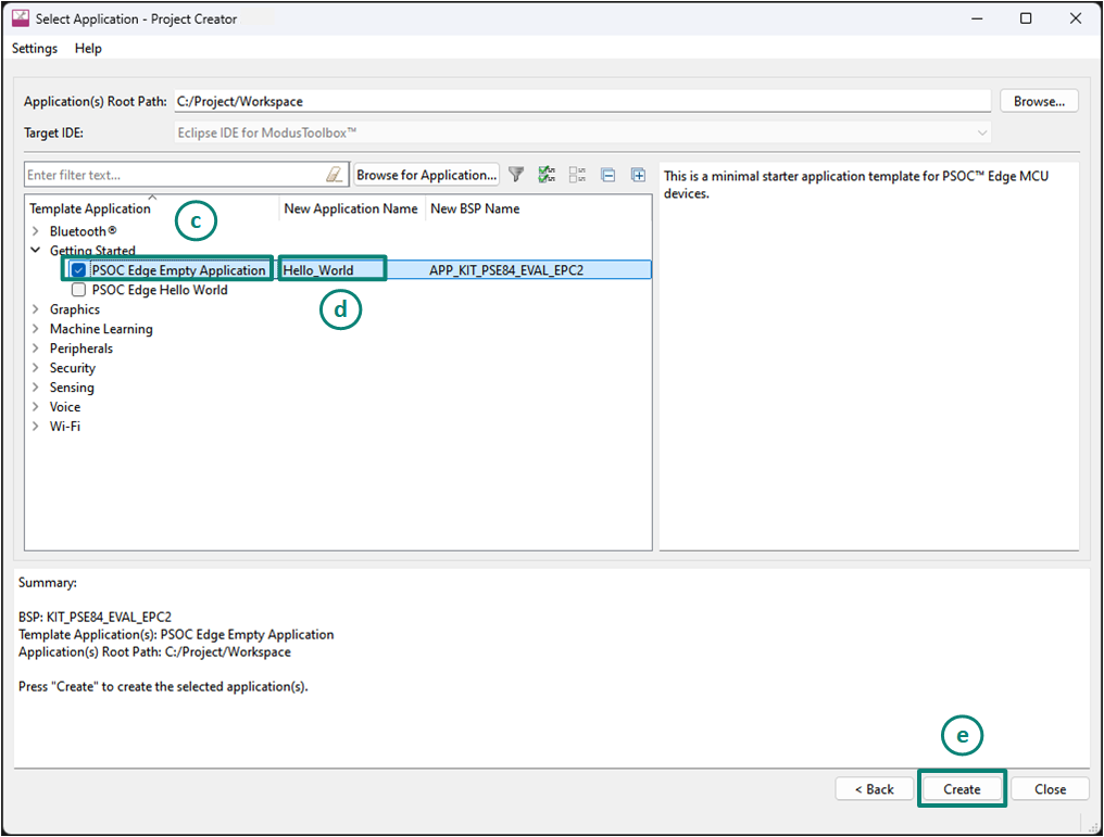
In the
Select Application
dialog, select
Empty App
starter application, as shown in
Figure 9
In the name field, type a name for the application, such as
Hello_World
. You can choose to leave the default name if you prefer
Click on
Create
and wait for the Project Creator to automatically close once the project is successfully created.
Figure 9.
Choose starter application
A new ModusToolbox™ application is created successfully.
View and modify the design
shows the Eclipse IDE Project interface, displaying the structure of the application project.
All
PSOC™ Edge
MCU applications have a dual-CPU three-project structure to develop code for the CM33 and CM55 cores. The CM33 core has two separate projects for the Secure Processing Environment (SPE) and Non-Secure Processing Environment (NSPE). A project folder consists of various subfolders, each denoting a specific aspect of the project.
Figure 10.
Project
PSOC™ Edge
view
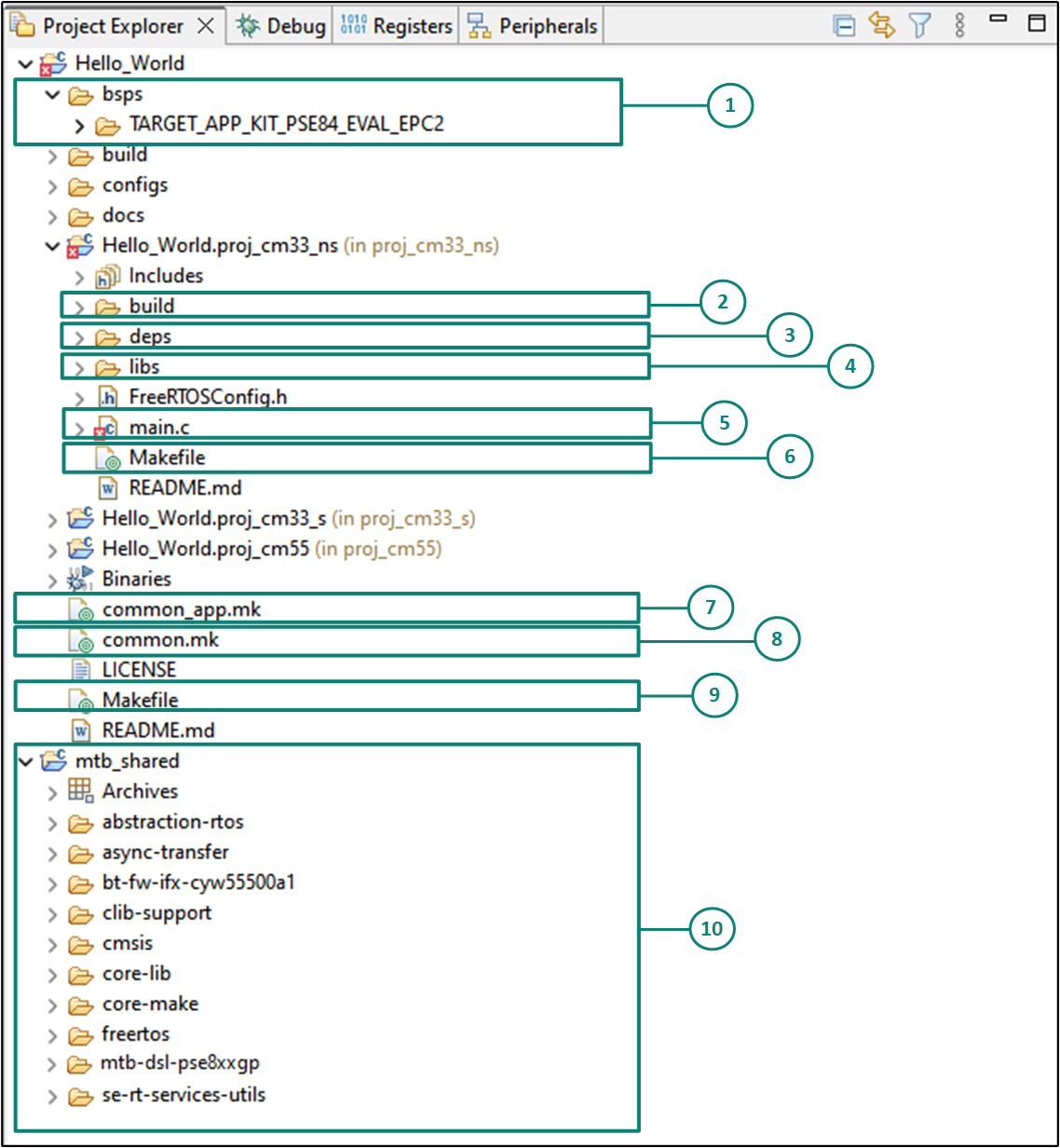
The following is the folder structure for one of the projects (proj_cm33_ns), as shown in
Figure 10
. A similar folder structure is present for the other two projects (proj_cm33_s) and (proj_cm55).
bsps folder
The bsps folder is common to all projects in a multi-core application. The files provided by the BSP are present here and are listed under the
TARGET_<bsp name>
sub-folders. All the input files for the device and peripheral configurators are in the
config
folder inside the BSP. The
Generated Source
folder in the BSP contains the files that are generated by the configurators and are prefixed with
cycfg_
. These files contain the design configuration as defined by the BSP. From ModusToolbox™ 3.x or later, you can directly customize BSP configurator files for the application rather than overriding the default design configurator files with custom design configurator files since BSPs are completely owned by the application.
The BSP folder also contains the linker scripts and the start-up code for the
PSOC™ Edge
MCU used on the board.
build folder
The build folder contains all the artifacts resulting from a build of the project. The output files are organized by target BSPs.
deps folder
The deps folder contains
.mtb
files, which provide the locations from which ModusToolbox™ pulls the libraries that are directly referenced by the application. For assets present in the manifest files, we use
mtb://
to fetch them into the project. For assets not present in the manifest, we use the GitHub location of that asset library in the
.mtb
file. The
.mtb
files also contain a git Commit Hash or Tag that tells which version of the library is to be fetched and a path as to where the library should be stored locally.
For example, if retarget-io is needed (as will be added later in this application note), then
retarget-io.mtb
points to
mtb://retarget-io#release-v2.0.200#$$ASSET_REPO$$/retarget-io/release-v2.0.200
. The variable
$$ASSET_REPO$$
points to the root of the shared location, which defaults to mtb_shared. If the library must be local to the application instead of shared, you may change to 'Local' in Library Manager.
This sub-directory also contains the
locking_commit.log
file, which keeps track of the version for each dependent library.
libs folder
The libs folder also contains
.mtb
files. In this case, they point to libraries that are included indirectly as a dependency of a BSP or another library. For each indirect dependency, the Library Manager places an .mtb file in this folder. These files have been populated based on the targets available in deps folder.
The libs folder contains the file
mtb.mk
, which stores the relative paths of the all the libraries required by the application. The build system uses this file to find all the libraries required by the application.
Everything in the libs folder is generated by the Library Manager; therefore, user is not expected to manually edit anything in that folder.
main.c
file
This is the file containing the source code of the project. Each project has its own source code file. If a project has multiple source code files, they can be grouped under a "source" folder.
Project-level Makefile
This is the project's Makefile. It includes numerous variables used for the projects, such as
COMPONENTS
,
CORE
,
CORE_NAME
, and other variables used to specify flags and pre-build and post build commands. This file also includes path information for source code discovery, shared repo location, and path to the compiler. Plus, it includes the
common.mk
file from the application and the path information to the start.mk file in the installation tools directory.
common_app.mk
file
This makefile is shared across the entire application and all its projects. It contains path information to indicate the location of the installation
tools_<version>
directory.
common.mk
file
This Makefile is shared across all projects. It contains variables including: MTB_TYPE, TARGET, TOOLCHAIN, and CONFIG. This file includes a reference to the
common_app.mk
file.
Application-level Makefile
An application contains a Makefile which is at the application's root folder. This file contains the set of directives that the make tool uses to compile and link the application project. This Makefile contains the
MTB_TYPE
variable set to
APPLICATION
, plus the
MTB_PROJECTS
variable to specify the included projects. This file also includes the
common_app.mk
file and the path information to the
application.mk
file in the installation
tools_<version>
directory. This is responsible for forwarding build related requests to the individual core projects and dealing with post-build activities (for example, generating single monolithic HEX files that can be used to program all projects simultaneously) when they are complete.
mtb_shared folder
By default, when creating a new application or adding a library to an existing application and specifying it as shared, all libraries are placed in an
mtb_shared
directory adjacent to the application directories.
The
mtb_shared
folder is shared between different applications within a workspace. Different applications may use different versions of shared libraries if necessary.
Each workspace you create with one or more applications will include a
mtb_shared
directory adjacent to the application directories, and this is where the shared libraries are cloned by default. To modify this location, specify the
CY_GETLIBS_PATH
variable. Duplicate libraries are checked to see if they point to the same commit, and if so, only one copy is kept in the
mtb_shared
directory. You can regenerate these files using the Library Manager as and when needed.
Opening the Device Configurator
BSP configurator files are in the
bsps/TARGET_<BSP-name>/config
folder. For example, click
<Application-name>
from
Project Explorer
then click
Device Configurator
link in the
Quick Panel
to open the file design.modus in the
Device Configurator
as shown in
Figure 12
. You can also open other configuration files in their respective configurators or click the corresponding links in the
Quick Panel
.
Note that this section is for information only and aims to get the user familiarized with the device configurator tool. All configurations needed for the Hello World demo is already present in the default design file. The user is not expected to do any device configuration changes for this demo.
Figure 11.
Select device configurator from quick panel
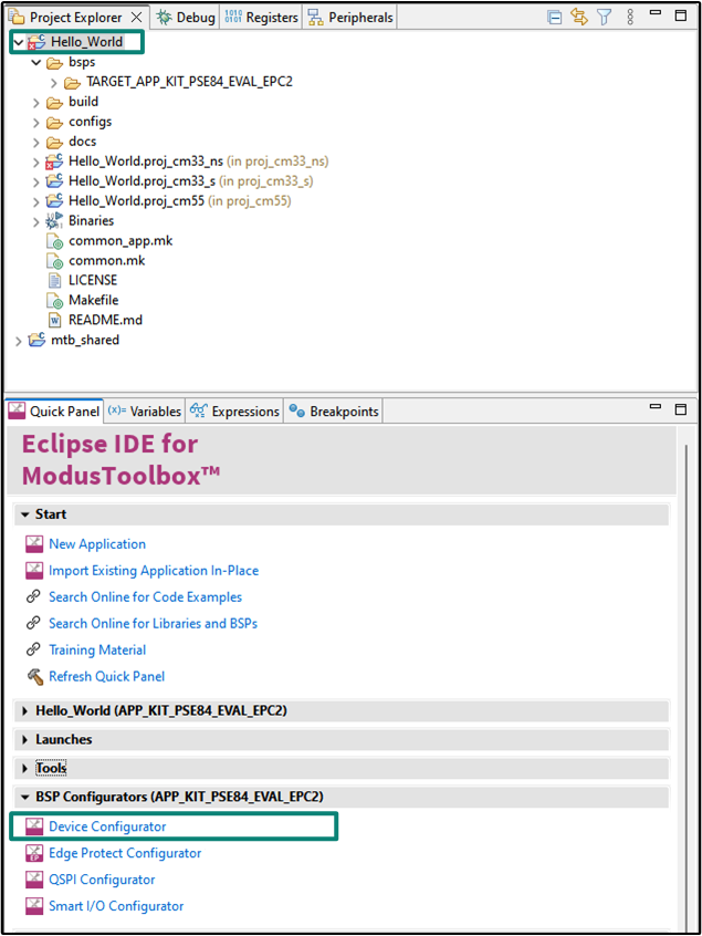
Figure 12.
Device Configurator
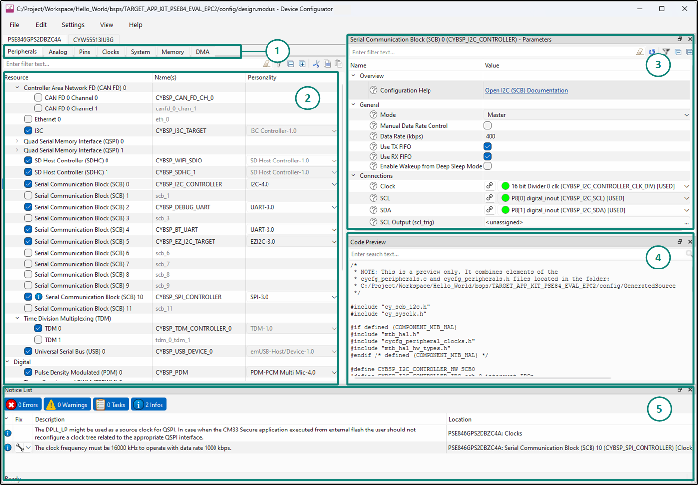
shows the following various panes in the device configurator GUI tool:
Resources and Categories pane
List of Resources
Parameters pane
Code Review pane
Notices pane
The
Device Configurator
provides a set of
Resources Categories
tabs. Here, you can choose between different resources available in the device such as peripherals, pins, and clocks from the
List of Resources
.
You can choose how a resource behaves by choosing a
Personality
for the resource. For example, a
Serial Communication Block (SCB)
resource can have
EZI2C
,
I2C
,
SPI
, or
UART
personalities. The
Alias
is the resource name, which is used in the firmware development. One or more aliases can be specified by using a comma or spaces to separate them.
The
Parameters
pane is where you enter the configuration parameters for each enabled resource and the selected personality. The
Code Preview
pane shows the configuration code generated per the configuration parameters selected. This code is populated in the
cycfg_
files in the
Generated Source
folder. The Parameters pane and Code Preview pane may be displayed as tabs instead of separate windows but the contents will be the same. Any errors, warnings, and information messages arising out of the configuration are displayed in the
Notices
pane. For more details, see the
Device Configurator userguide
.
The default BSP comes with a few peripherals pre-configured. You may change these configurations and settings or add your own as per requirement of your application. These configurations can be directly utilized by the application code to implement the functionality of configured resources. For more details, see
Write firmware
.
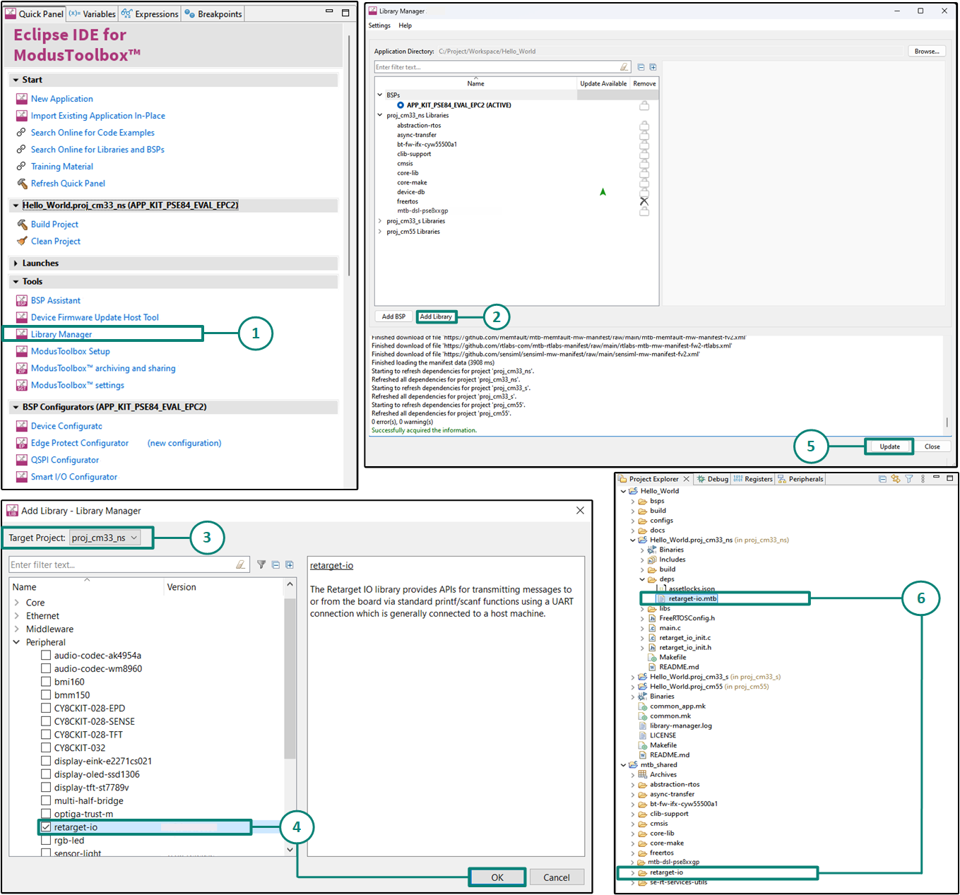
Add retarget-io middleware
In this step, add the
retarget-io
middleware to redirect standard input and output streams to the UART configured by the BSP. The middleware initialization is done in the
main.c
file. Do the following to add this middleware, as shown in
Figure 13
:
First select the application in the project explorer and then In the
Quick Panel
, click
Library Manager
In the subsequent dialog, click
Add Libraries
Select the
Target Project
as
proj_cm33_ns
because this is the project in which we will be writing our application code
Under
Peripherals
, select and enable
retarget-io
and click
OK
Click
Update
to add the library to that project
The
retarget-io.mtb
file pointing to the Retarget-IO middleware is added to the application project's deps directory. The middleware content is also downloaded and placed inside the corresponding folder called retarget-io. The default location is in the shared asset repo that is mtb_shared
Figure 13.
Add the retarget-io middleware
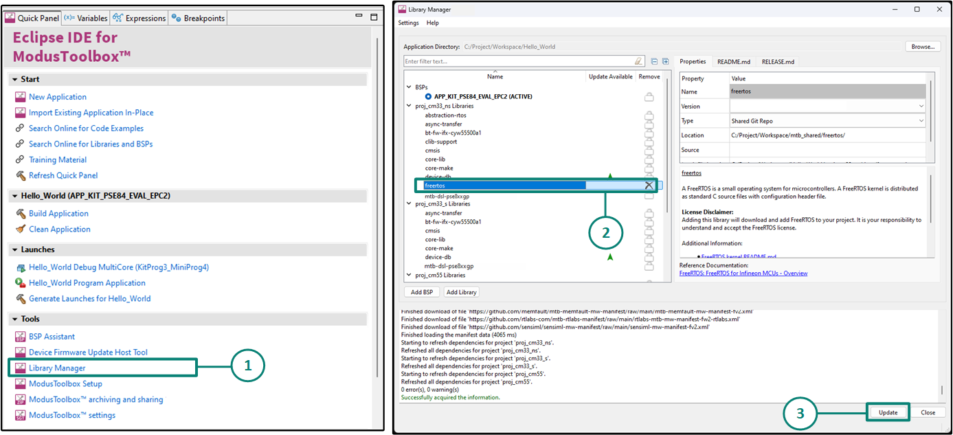
Remove FreeRTOS library
The FreeRTOS library comes with the Empty Application code example. If you are using the Empty Application to create an application which does not use FreeRTOS, you will need to remove the library.
In this example, Empty Application is being modified into a Hello World application which does not require any RTOS for its functionality; thus, FreeRTOS should be removed from the library manager. You should also remove the RTOS related contents of the
"COMPONENTS"
variable in the project-level Makefiles.
Follow the next steps to remove the middleware, as shown in
Figure 14
:
Open
Library Manager
from the Quick Panel
Select
FreeRTOS
in the proj_cm33_ns libraries list and click on the "cross" button next to the library
Click
Update
to remove FreeRTOS from the project. Similarly, the library can be removed from other project (proj_cm55) as well
In each of the project-level
Makefiles
, delete the "
FREERTOS
and
RTOS_AWARE
" from the
COMPONENTS
variable
COMPONENTS+=
FREERTOS RTOS_AWARE
Delete the
FreeRTOSConfig.h
file present in each project
Figure 14.
Remove FreeRTOS from the project
Write firmware
At this stage in the development process, an application was created with the assistance of an application template and modified it to add the
retarget-io
middleware and remove freeRTOS middleware. In this section, the firmware implementing the design functionality will be written.
If you are working from scratch using the
PSOC™
Edge
Empty Application
, copy the respective source code to the
main.c
of the application project from the code snippet provided in this section. If you are using the
Hello World
code example, all the required files are already in the application.
Firmware flow
Examine the code in the
main.c
files of the non-secure CM33 project and the CM55 project. A basic secure CM33 project is also provided with applications for necessary security initializations and configurations. In this example, we use the default secure CM33 project; however, this can be modified to suit the use-case.
Figure 15
shows the firmware flowchart.
At device reset, the secure boot process starts from the ROM boot with the secure enclave (SE) as the root of trust (RoT). From the secure enclave, the boot flow is passed on to the system CPU subsystem where the secure CM33 application starts. After all necessary secure configurations, the flow is passed on to the non-secure CM33 application. Resource initialization for this example is performed by this CM33 non-secure project. It configures the system clocks, pins, clock to peripheral connections, and other platform resources. It then enables the CM55 core using the
Cy_SysEnableCM55()
function and the CM55 core is subsequently put to DeepSleep mode.
In the CM33 non-secure application, the BSP initialization function initializes the clocks and system resources. The
retarget-io
middleware is configured to use the debug UART. The debug UART prints a “Hello World!” message on the terminal emulator using the on-board KitProg3 acting as a USB-UART bridge to create a virtual COM port. The user LED's output logic state is continuously toggled with a delay of 1000 milliseconds.
Note that the application code uses BSP, PDL, and middleware functions to execute the intended functionality. You can open the Device Configurator to view the aliases that are setup in the BSP.
-
cybsp_init(): Sets up the BSP and initializes all the system resources of the device including system clocks and power regulators. It also performs device and memory security configurations when called from the Secure Processing Environment (SPE) -
init_retarget_io(): This is a user defined function to initialize the debug UART. It uses the aliases set up in the BSP for the debug UART pins to configure the debug UART using the Retarget IO middleware with a standard baud rate of 115200 and redirects the input/output stream to the debug UART Cy_SysEnableCM55()
: This API is used to enable the CM55 core
Cy_GPIO_Inv()
: The user LED is already configured in the BSP. This API is used to toggle the pin's output logic state
Figure 15.
Firmware flowchart
Code Listing 1
:
main.c
file from the non-secure CM33 project
proj_cm33_ns
/*******************************************************************************
* File Name        : main.c
*
* Description      : This source file contains the main routine for non-secure
*                    application in the CM33 CPU
*
* Related Document : See README.md
*
********************************************************************************
* $ Copyright 2023-YEAR Cypress Semiconductor $
*******************************************************************************/

/*******************************************************************************
* Header Files
*******************************************************************************/

#include "cybsp.h"
#include "retarget_io_init.h"

/*******************************************************************************
* Macros
*******************************************************************************/
#define BLINKY_LED_DELAY_MSEC       (1000U)

/* The timeout value in microseconds used to wait for CM55 core to be booted */
#define CM55_BOOT_WAIT_TIME_USEC    (10U)

/* App boot address for CM55 project */
#define CM55_APP_BOOT_ADDR          (CYMEM_CM33_0_m55_nvm_START + \
                                   CYBSP_MCUBOOT_HEADER_SIZE)

/*******************************************************************************
* Function Name: main
********************************************************************************
* Summary:
* This is the main function of the CM33 non-secure application.
*
* It initializes the device and board peripherals. It also initializes the
* retarget-io middleware to be used with the debug UART port using which
* "Hello World!" is printed on the debug UART. The LED pin is initialized with
* default configurations. The CM55 core is enabled and then the programs enters
* an infinite while loop which toggles the LED1 with a frequency of 1 Hz.
*
* Parameters:
*  none
*
* Return:
*  int
*
*******************************************************************************/
int main(void)
{
cy_rslt_t result = CY_RSLT_SUCCESS;

/* Initialize the device and board peripherals. */
result = cybsp_init();

/* Board initialization failed. Stop program execution. */
if (CY_RSLT_SUCCESS != result)
{
   handle_app_error();
}

/* Enable global interrupts */
__enable_irq();

/* Initialize retarget-io middleware */
init_retarget_io();

/* \x1b[2J\x1b[;H - ANSI ESC sequence for clear screen. */
printf("\x1b[2J\x1b[;H");

printf("****************** "
      "PSOC Edge MCU: Hello world "
      "****************** \r\n\n");

printf("Hello World!\r\n\n");
printf("For more projects, "
      "visit our code examples repositories:\r\n\n");

printf("https://github.com/Infineon/"
      "Code-Examples-for-ModusToolbox-Software\r\n\n");

/* Enable CM55. */
/* CM55_APP_BOOT_ADDR must be updated if CM55 memory layout is changed.*/
Cy_SysEnableCM55(MXCM55, CM55_APP_BOOT_ADDR, CM55_BOOT_WAIT_TIME_USEC);

for(;;)
{
   Cy_GPIO_Inv(CYBSP_USER_LED1_PORT, CYBSP_USER_LED1_PIN);
   Cy_SysLib_Delay(BLINKY_LED_DELAY_MSEC);
}
}

/* [] END OF FILE */
Code Listing 3
:
retarget_io_init.h
file from the CM33 project
proj_cm33_ns
project
/*******************************************************************************
 * File Name:   retarget_io_init.h
 *
 * Description:  This file is the public interface of retarget_io_init.c and
 *               contains the necessary UART configuration parameters.
 *
 * Related Document: See README.md
 *
 *******************************************************************************
* $ Copyright 2023-YEAR Cypress Semiconductor $
*******************************************************************************/

#ifndef _RETARGET_IO_INIT_H_
#define _RETARGET_IO_INIT_H_

/*******************************************************************************
* Header Files
*******************************************************************************/
#include "cybsp.h"
#include "mtb_hal.h"
#include "cy_retarget_io.h"
#include "mtb_syspm_callbacks.h"

/*******************************************************************************
* Macros
*******************************************************************************/

/* retarget-io deepsleep callback macros */
#define DEBUG_UART_RTS_PORT     (NULL)
#define DEBUG_UART_RTS_PIN      (0U)

/* Default syspm callback configuration elements */
#define SYSPM_SKIP_MODE         (0U)
#define SYSPM_CALLBACK_ORDER    (1U)


/*******************************************************************************
* Function prototypes
*******************************************************************************/
void init_retarget_io(void);

/*******************************************************************************
* Function Name: handle_app_error
********************************************************************************
* Summary:
* User defined error handling function
*
* Parameters:
*  void
*
* Return:
*  void
*
*******************************************************************************/
__STATIC_INLINE void handle_app_error(void)
{
    /* Disable all interrupts. */
    __disable_irq();

    CY_ASSERT(0);

    /* Infinite loop */
    while(true);
}

#endif /* _RETARGET_IO_INIT_H_ */

/* [] END OF FILE */
Code Listing 4
:
main.c
file from the CM55 project
proj_cm55
/*******************************************************************************
* File Name        : main.c
*
* Description      : This source file contains the main routine for CM55 CPU
*
* Related Document : See README.md
*
********************************************************************************
* $ Copyright 2023-YEAR Cypress Semiconductor $
*******************************************************************************/

/*******************************************************************************
* Header File
*******************************************************************************/

#include "cybsp.h"

/*******************************************************************************
* Function Name: main
********************************************************************************
* Summary:
* This is the main function for CM55 application.
*
* CM33 application enables the CM55 CPU and then the CM55 CPU enters
* deep sleep.
*
* Parameters:
*  void
*
* Return:
*  int
*
*******************************************************************************/
int main(void)
{
    cy_rslt_t result;

    /* Initialize the device and board peripherals */
    result = cybsp_init();

    /* Board init failed. Stop program execution */
    if (CY_RSLT_SUCCESS != result)
    {
        /* Disable all interrupts. */
        __disable_irq();

        CY_ASSERT(0);

        /* Infinite loop */
        while(true);
    }

    /* Enable global interrupts */
    __enable_irq();

    /* Put the CPU to Deep Sleep */
    for (;;)
    {
        Cy_SysPm_CpuEnterDeepSleep(CY_SYSPM_WAIT_FOR_INTERRUPT);
    }
}

/* [] END OF FILE */
This completes the summary of how the firmware works in the code example. For more detailed information, see the source files.
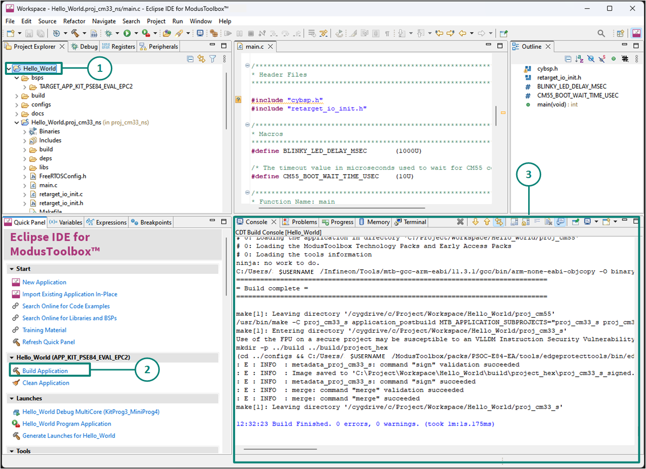
Build the application
This section explains how to build the application. Follow these steps, as shown in
Figure 16
:
Select the application project in the
Project Explorer
view
Click
Build Application
shortcut under the
Hello_World (APP_KIT_PSE84_EVAL_EPC2)
group in the
Quick Panel
It selects the build configuration from Makefiles and compiles or links all projects that constitute the application. By default, debug configurations are selected. The
Console view
lists the results of the build operation, as shown in
Figure 16
Figure 16.
Build the Application
Note:
You can also use the command-line interface (CLI) to build the application. See the
Build system chapter
in the
ModusToolbox™ tools package user guide
. This document is located in the
/ docs_<version>/
folder in the ModusToolbox™ installation directory.
Program the device
This section explains how to program the
PSOC™ Edge
MCU.
The ModusToolbox™ software uses the
Open On-Chip Debugger (OpenOCD)
to program and debug applications on
PSOC™ Edge
MCUs. For ModusToolbox™ software to identify the device on the kit, the kit must be running KitProg3. For more details, see
Programming and Debugging
.
If you are using a development kit with a built-in programmer, connect the board to the computer using the USB cable. You may also need to update KitProg firmware using the fw-loader tool. The tool and instructions are available in the
Firmware Loader
GitHub repository. If you do not upgrade, you will see an error, such as "unable to find CMSIS-DAP device" or "KitProg firmware is out of date". For more information, please refer to
Firmware Loader user guide
.
Note that for the provisioning flow, the minimum required version of KitProg3 firmware is 2.60.1412. To update the KitProg3 firmware on
PSOC™
Edge E84 Evaluation kit (KIT_PSE84_EVAL_EPC2), do the following:
Open modus-shell present at location
<install-location>/ModusToolbox/tools_x.x/modus-shell
in the ModusToolbox™ installation directory
Paste and run the following command
fw-loader --update-kp3
If you are developing on your own hardware, you may need a hardware programmer and debugger; for example, a
JLink
or
ULinkpro
.
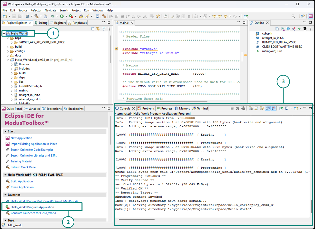
To program the application, do the following, as shown in
Figure 17
:
Select the project
Hello_World
Select the application project and click the
Hello_World Program Application (KitProg3_MiniProg4)
shortcut under the
Launches
group in the
Quick Panel
, as
Figure 17
shows. The IDE selects and runs the appropriate run configuration
The
Console
lists the results of the programming operation
Figure 17.
Programming an application to a device
This step also performs a build if any files have been modified since the last build.
Test your design
This section describes how to test the design.
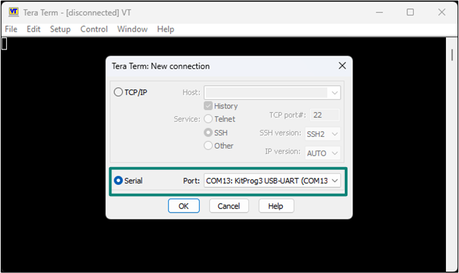
Do the following steps to observe the output of the design. This application note uses TeraTerm as the UART terminal emulator to view the results. You can use any serial terminal to view the output.
Select the serial port
Launch
Tera Term
and select the USB-UART COM port as
Figure 18
shows. Note that COM port number may be different.
Figure 18.
Selecting the KitProg3 COM port in Tera Term
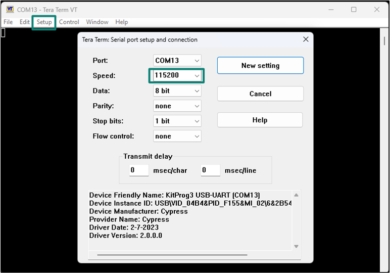
Set the baud rate
Set the baud rate to 115200 under Setup > Serial port, as shown in
Figure 19
.
Figure 19.
Configuring the baud rate in Tera Term
Reset the device
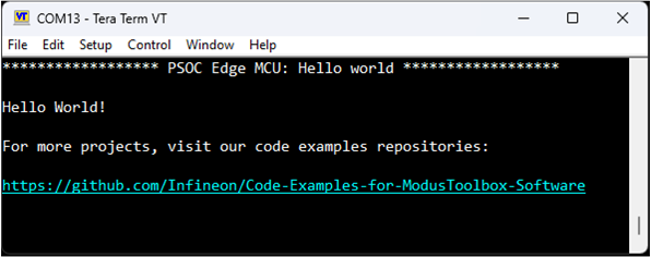
Press the reset switch (SW1) on the kit. A message appears on the terminal, as shown in
Figure 20
. The user LED on the kit starts blinking.
Figure 20.
Printed UART message
Booting from external OSPI flash
The
PSOC™
Edge Evaluation Kit (EVK) supports booting from the following two external memories:
Quad Serial Peripheral Interface (QSPI) flash
Octal Serial Peripheral Interface (OSPI) flash
They are connected to the same serial memory interface (SMIF) through two different slave select lines. All code examples including the Hello World application, are configured to boot from the external QSPI flash.
This section is entirely optional and serves as a guide for users who wish to switch from the external Quad SPI flash memory to the external Octal SPI flash memory.
To check the version of Extended Boot, open modus-shell and execute one of the following command depending on the device. This command expects edgeprotecttools bin directory in the path environment variable.
edgeprotecttools -t pse8xs2 device-info
or
edgeprotecttools -t pse8xs4 device-info
To update/replace the Extended Boot present in the
PSOC™
Edge device, see section
Replacing the Extended Boot
in the
AN237849 - Getting Started with
PSOC™
Edge Security
document.
Provision the
PSOC™
Edge EVK with the correct set of configurations required for switching the boot flow to Octal SPI. For details about provisioning and policy configurations, see section
Switching between Octal and Quad SPI external flash memory
in the
AN237849 - Getting Started with the
PSOC™
Edge Security
document
Open Device Configurator. In the' Memory Tab', delete all configured memory regions under Serial Memory Interface (SMIF) Block 0, Memory 1. For details on editing memory regions, refer the section 'Memory tab' of the
Infineon Device Configurator User Guide
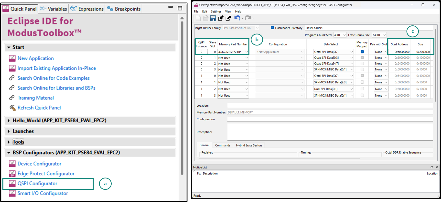
Use the ModusToolbox™ QSPI configurator to update configuration files, configure memory slots, and generate code for your application to allow it to program into the external Octal SPI flash, see
Figure 21
.
You can launch the QSPI configurator GUI using either of the below methods:
On the Eclipse IDE, click on the
QSPI configurator
under BSP configurators (APP_KIT_PSE84_EVAL_EPC2)
On the command-line, open modus-shell, navigate to the
<application-directory>
of the code example, and run the following 'make' command:
make qspi-configurator
It can be observed that the current configuration supports the external Quad SPI flash. In the first row, with
QSPI Instance 0
and
Slave Slot 0
, click on the drop-down menu for the column
Memory Part Number
and select
Auto Detect SFDP
. For the second row with
QSPI Instance 0
and
Slave Slot 1
, set the
Memory Part Number
and select
Not Used
Set the memory start address for the Octal SPI flash to
0x60000000
, the same as configured for the Quad SPI flash. The memory size can be left as the default
0x20000000
as the SMIF0 (XIP_Port0) region has a maximum size of 64 MB
Save the QSPI configuration file
Figure 21.
Launching the QSPI configurator and configuring the booting from OSPI flash
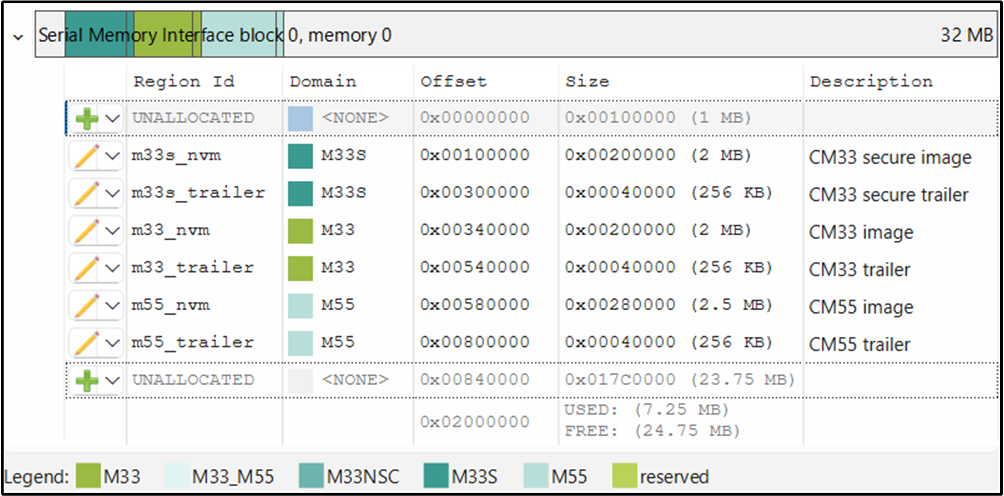
In the Device Configurator, open the Memory tab. Under Serial Memory Interface (SMIF) Block 0, Memory 0, add the memory regions to match the layout shown in
Figure 22
. Adjust each region’s size as needed for your application.
Figure 22.
Memory regions for OSPI flash
We can now program the application into the external Octal SPI flash. Build the code example and program it onto the
PSOC™
Edge EVK. The
PSOC™
Edge EVK is now provisioned with configurations to enable boot from external OSPI flash (SMIF0)
The EVK can either boot from the internal RRAM memory or from the external OSPI flash, depending on the BOOT SW switch configuration. The EVK will not work with the other code examples that are configured to run from Quad SPI flash out of the box. To move back to Quad SPI flash, revert the SMIF policy configurations and provision the
PSOC™
Edge EVK again with the updated policy. Refer to the
AN237849 - Getting Started with
PSOC™
Edge Security document
for more detail.
Summary
This application note demonstrated the
PSOC™ Edge
MCU device architecture and the associated development tools required for creating and modifying an application to utilize the varied functionality of this MCU.
The
PSOC™ Edge
MCU is a truly programmable embedded system-on-chip with configurable analog and digital peripheral functions and memory. It is highly versatile dual-CPU microcontroller with a neural net companion processor on a single chip. The integrated features and low-power modes make
PSOC™ Edge
MCU an ideal choice for smart home, IoT gateways, and other related applications.
References
Glossary
This section lists the most commonly used terms that you might encounter while working with
PSOC™
family of devices.
Board support package (BSP) : A BSP is the layer of firmware containing board-specific drivers and other functions. The board support package is a set of libraries that provide firmware APIs to initialize the board and provide access to board level peripherals
PSOC™ Programmer : Cypress Programmer is a flexible, cross-platform application for programming Cypress devices. It can Program, Erase, Verify, and Read the flash of the target device
KitProg: The KitProg is an onboard programmer/debugger with USB-I2C and USB-UART bridge functionality. The KitProg is integrated onto most PSOC™ development kits
MiniProg3 / MiniProg4 : Programming hardware for development that is used to program PSOC™ devices on your custom board or PSOC™ development kits that do not support a built-in programmer
Personality: A personality expresses the configurability of a resource for a functionality. For example, the SCB resource can be configured to be an UART, SPI or I2C personalities
PSOC™ : A programmable, embedded design platform that includes a CPU, such as the 32-bit Arm® Cortex®-M0, with both analog and digital programmable blocks. It accelerates embedded system design with reliable, easy-to-use solutions, such as touch sensing, and enables low-power designs
Middleware : Middleware is a set of firmware modules that provide specific capabilities to an application. Some middleware may provide network protocols (e.g. MQTT), and some may provide high level software interfaces to device features (e.g. USB, audio)
Peripheral driver library (PDL): The peripheral driver library (PDL) simplifies software development for the PSOC™ MCU family. PDL contains a set of low-level APIs to control hardware peripherals such as UART and SPI. The interfaces are usually specific to a particular micro-controller or micro-controller family. Since the PDL interacts with the hardware at a lower level it is less portable between devices, especially those with different architectures. The PDL reduces the need to understand register usage and bit structures, therefore easing software development for the extensive set of peripherals available
Hardware abstraction layer (HAL): HAL provides a generic, device agnostic interface that can be used across multiple product families. The HAL is designed for portability, not as a general-purpose user library. HAL drivers are thin wrappers around lower-level device specific (e.g.: PDL) APIs and are focused on the runtime behavior of the hardware, not initialization. The HAL is designed to be compatible with a wide range of devices including low memory, multi-core, connectivity and secure devices
ModusToolbox™ : An Eclipse based embedded design platform for IoT designers that provides a single, coherent, and familiar design experience combining the industry's most deployed Wi-Fi and Bluetooth® technologies, and the lowest power, most flexible MCUs with best-in-class sensing
Revision history
Document revision | Date | Description of changes |
|---|---|---|
*I | 2025-09-15 | Release to web |
Trademarks
The Bluetooth® word mark and logos are registered trademarks owned by Bluetooth SIG, Inc., and any use of such marks by Infineon is under license.
PSOC™, formerly known as PSoC™, is a trademark of Infineon Technologies. Any references to PSoC™ in this document or others shall be deemed to refer to PSOC™.