AN241775 Getting started with Hardware Abstraction Layer (HAL) on PSOC™ Edge MCU
About this document
Scope and purpose
This document introduces
the new Hardware Abstraction Layer (HAL) library for Infineon PSOC™ Edge MCUs.
Intended audience
This document is intended for users who are looking to migrate their applications to use the new HAL library or use it in their applications in ModusToolbox™ applications.
Introduction to Infineon’s new Hardware Abstraction Layer (HAL)
The Infineon device support library combines content from several distinct software packages into a single package which includes the following software packages: The Peripheral Driver library (PDL), Device utilities, Device information and Hardware abstraction Layer (HAL).
Figure 1
shows a high-level overview of the software stack used in a ModusToolbox™ application.
Figure 1.
ModusToolbox™ software stack
The Infineon Hardware Abstraction Layer (HAL) for PSOC™ Edge device family has undergone significant changes compared to the legacy HAL supported for PSOC™ 6 and other device families, refocusing on the needs of middleware and streamlining its functionality.
The new HAL eliminates unnecessary APIs and drivers, de-emphasizing its usage in the application layer while focusing on middleware support. Configuration can be handled via the Device Configurator, with initialization performed by the Peripheral Driver Library (PDL). Hardware resource management, peripheral initialization and routing configurations including pins and clocks, and other higher-level functionalities, previously abstracted by legacy HAL, is now completely handled at the PDL level, with improved transparency and customization. Some of these responsibilities are handled by the configurator tools running on the desktop. The tasks which previously consumed MCU resources to perform at runtime are now performed once at the design configuration stage itself, thereby improving runtime performance.
The HAL now focuses on portability, providing a consistent interface across different hardware platforms. This guide will walk users through the changes, new procedures, and best practices for using the updated HAL, ensuring a smooth transition and optimal performance.
What is the new HAL?
The functionality of legacy HAL is now split into different components as shown in
Figure 2
.
Figure 2.
Comparison between legacy and new HAL
below captures the high-level functional differences between legacy and new HAL and also establishes the reasoning behind the update.
Parameter | Legacy HAL | new HAL |
|---|---|---|
Purpose and layering clarity | Legacy HAL often blended features and hidden setup steps that sometimes hid what was happening at the device level | The new HAL becomes a separate layer focused on serving the middleware |
Configuration and initialization split | The configuration and initialization patterns were often mixed, or done via HAL helpers that abstracted device setup | The new HAL expects that the resource must be enabled either in the configurator or directly in the application code using PDL APIs. Middleware talks to a consistent HAL API once the device is set up |
Moving functionality down to PDL | Some higher-level functionality lived in the HAL, potentially masking device differences | This new design re-centers device-dependent behavior in the PDL layer, where it belongs. This improves predictability, performance tuning, and debug experience of applications Some high-level HAL functionality (like IPC and Async Transfer) is split into separate libraries that can be used together with either HAL or PDL |
Enables transparency | The legacy HAL relied on behind-the-scenes 'magic' like auto-allocation, implicit power or clock steps | The new HAL defines explicit code paths and clearer control. This helps certification, analysis, and maintenance specially for safety and security sensitive applications |
Using new HAL with ModusToolbox™ code examples
As discussed in the earlier section, ModusToolbox™ code examples will no longer directly interface with the HAL drivers. All code examples supporting the PSOC™ Edge family of devices use the new design flow for HAL usage.
In case of middleware usage, the expected flow is as follows:
Application initializes and enables the peripheral using configurator-generated PDL configuration structures or via the PDL APIs
Application then sets up the peripheral with a context object using HAL APIs. Note that this step only initializes the HAL data structures and does not initialize the hardware
The HAL object is then passed on to the middleware which performs the requested operations using configurator-generated HAL API
See the sequence diagram in the
Figure 3
for the expected ModusToolbox™ application flow.
Figure 3.
Application flow diagram for usage with or without middleware
This application note guides you about the workflows necessary for setting up and using HAL in code examples. This document covers a high-level overview of necessary concepts for understanding HAL, and provides pointers to migrate an existing HAL-based code example to new HAL-based approach featuring example code snippets.
Important concepts for understanding HAL
Typical HAL setup sequence
There are two broad buckets of HAL driver API organization:
Setup functions: Initialize a HAL object for a specific hardware instance
Runtime functions: Perform operations after setup (read, write, start, stop, etc.)
This section describes how to use the setup function in PSOC™ Edge applications. The setup function has the following signature:
mtb_hal_<functional_block>_setup(mtb_hal_<functional_block>_t* obj,
                                mtb_hal_<functional_block>_config_t* cfg,
                                cy_stc_<functional_block>_context_t* context,
                                mtb_hal_clock_t* clock);
Parameter | Description |
|---|---|
Pointer to a driver-specific HAL object (for example, ) | You must allocate this object in the application and then pass it into the setup function. This HAL object should be treated as a handle and its fields should not be modified by the application. The setup function will use this object to initialize the instance for usage by subsequent runtime HAL functions You must always pass the same object to all subsequent runtime APIs for that hardware instance. If this HAL object is passed into other libraries that use the HAL, it must be passed as a pointer reference |
Pointer to the HAL configuration structure (for example, ) | This is generally generated by the Infineon Device Configurator tool at build time for the configured resource. You can also define this structure at application level when required. This structure contains the hardware configuration parameters needed for HAL operations. The configuration structures are available in the folder For drivers that support clock configuration, this structure includes a pointer to an that provides the HAL’s default clock interface functions |
Pointer to the PDL context structure (for example, ) | Some drivers require this additional context object for low-level implementation. It is an internal, opaque object used by the driver. The firmware should not read from it or write to it The application is responsible for allocating the context and passing it by reference to the driver’s setup and runtime functions. The same context pointer must also be passed to the PDL initialization function which is called before the HAL setup The application must ensure that the allocated context structure is valid and in scope while the peripheral instance is in use |
Pointer to a custom clock instance (for example, ) | Optional parameter. You may pass this if a custom clock interface function is required. A common use case is split responsibilities across security domains:
If a custom clock interface is not required, you may pass for this parameter. In this case, the HAL uses the default clock interface from the HAL configuration structure |
The following is an example code snippet for UART initialization using HAL:
/* Application code starts */

/* Application-owned instances */
mtb_hal_uart_t uart_obj;                    /* Opaque handle for the UART */
const mtb_hal_config_t* uart_cfg = ...      /* Generated by the device configurator */
cy_stc_scb_uart_context_t uart_context = .../* Opaque context structure for PDL */
const mtb_hal_clock_t custom_clock = ...    /* Optional custom clock interface */

/* Setup: provide the object, configuration, and optionally a custom clock */
mtb_hal_uart_setup(&uart_obj, &hal_cfg, &uart_context, &custom_clock);

/* If not overriding the clock, pass NULL: */
// mtb_hal_uart_setup(&uart_obj, &hal_cfg, &uart_context, NULL);

/* Application code ends */

/* Middleware code starts */

/* Use the same object for all runtime operations */
mtb_hal_uart_write(&uart_obj, tx_buf, tx_len);
mtb_hal_uart_read(&uart_obj, rx_buf, rx_len);

/* Middleware code ends */
For a more detailed discussion, see section
Examples for HAL usage with middleware
.
Initialization sequence
The application is responsible for initializing the hardware that middleware libraries will access through the HAL. You may refer to the retarget-io initialization sequence in the
PSOC Edge MCU: Hello World
code example.
The HAL instance should be initialized in the following sequence:
Initialize the peripheral with the PDL APIs
Enable the peripheral using the PDL APIs
Set up the corresponding HAL object using the
_setup
function
Initialize the middleware using the same HAL object
If applicable, configure and enable the interrupt handler using the PDL APIs
If present, register the
SysPm
callback handler using the PDL APIs
When the Device Configurator is used to set up the hardware, it automatically generates configuration structures. The application may ignore these generated structures and define them manually if required.
RTOS integration
Some HAL drivers can behave differently in an RTOS environment, especially for operations that need to wait for a significant amount of time. In an RTOS-aware configuration, these functions perform waits through the RTOS API so other threads can continue running. In non-RTOS (bare-metal) environments, they use busy-wait loops instead. To indicate that an RTOS is in use, enable the
RTOS_AWARE
component (
COMPONENTS+=RTOS_AWARE
) in the project Makefile. When this is set, the HAL uses the
RTOS Abstraction APIs
to handle waits.
When using the HAL in an RTOS environment with the
RTOS_AWARE
component enabled, HAL driver setup must occur after the RTOS has been initialized to ensure that RTOS resources, such as semaphores used by the HAL drivers, are properly initialized.
It is not safe to invoke more than one operation on the same HAL driver instance at the same time. If multiple threads access a HAL driver instance, the caller is responsible for enforcing mutual exclusion (for example, with an RTOS mutex or semaphore) so that only one thread interacts with that instance at any given time.
SysPm callbacks
Two kinds of APIs exist in the legacy system power management (SysPm) HAL:
Power state transitions: The functions like
cyhal_syspm_enter_deepsleep()
that help in transitioning across the device’s power mode
Callback support: These APIs help to decide if it’s safe to change power modes and to prepare/restore peripherals around those transitions
The new HAL keeps the power mode transition functions (e.g. ,enter Sleep/DeepSleep) but does not keep the functions to transition between different active power states like (Low Power (LP), Ultra Low Power (ULP) and High performance (HP)). Middleware (for example, an RTOS) can call these APIs to enter low-power modes. The application must take care of all steps (including changing the core voltage and system clock frequencies) necessary to prepare for or restore after a transition to a low-power state.
The new HAL no longer auto-registers the System Power Management (
SysPm
) callbacks. It is the application's responsibility to register callbacks where necessary. The PDL provides ready-made, default callback implementations for common peripherals. The Device Utilities (device-utils) handles the pre-defined
SysPm
callback implementations for peripherals which require special handling when the MCU enters or exits DeepSleep. This helps in having a reliable and controlled power management experience.
Clock management
The application is responsible for setting up and initializing clocks, either directly through PDL API or through Device Configurator GUI. Some HAL drivers may need to adjust a clock at run time (for example, changing a UART baud rate). To enable this, each driver’s
_setup
function accepts an optional
mtb_hal_clock_t
pointer that provides a clock interface the driver can use. See section
Initialization sequence
for details.
There are now two ways to provide the clock interface
The configurator generates a structure (often referenced as
_hal_config
) for all initialized peripherals that includes a pointer to the HAL’s default clock interface (
mtb_hal_clock_t
). If no custom clock interface is supplied (parameter passed as
NULL
), the driver will use this default interface automatically. This is ideal for simple applications that don’t need special clock handling
In case custom clock control is required for a peripheral, you must pass the relevant custom clock interface to the
_setup
function. A common use case is when the secure partition owns clock management, while a non-secure partition owns the peripheral. The custom clock interface can enforce that separation
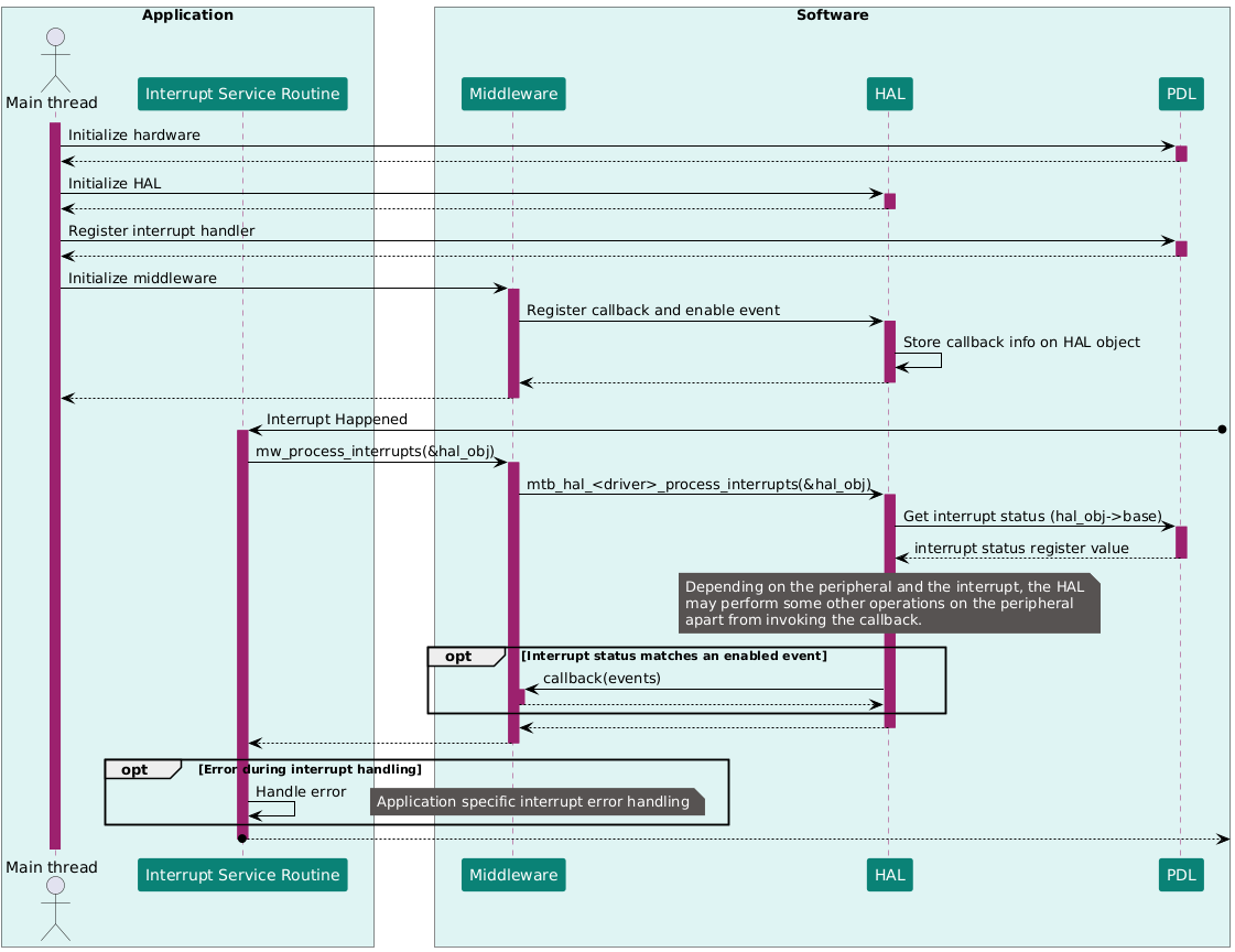
Interrupt handling
HAL drivers that support interrupt handling expose a function to process peripheral interrupts (commonly named process_interrupts or
_process_interrupt
). Any middleware that relies on such a HAL driver provides its own wrapper around the driver’s interrupt-processing functions.
For every peripheral instance used by a middleware (and typically for instances the application uses directly as well), the application is responsible for implementing and registering the interrupt handler. That handler must invoke the corresponding middleware-level interrupt processing function for that specific instance. This instance-by-instance linkage ensures that interrupts are routed correctly, preserves the separation of concerns among the application, middleware, and HAL, and keeps the interrupt path consistent across the code base.
See
Figure 4
for a sequence diagram on the interrupt handling mechanism in Modustoolbox™ applications which use HAL through middlewares.
Figure 4.
Interrupt handling using HAL
Guide to migrate code examples from legacy HAL-based code examples
This section provides tips and suggestions to migrate existing HAL-based code examples to either completely PDL-based or PDL with HAL for middleware setup. All PSOC™ Edge code examples available in ModusToolbox™ already follow this strategy.
The legacy Infineon HAL provided a generic interface which was supposed to be used across multiple MCU product families. This was achieved by having the HAL as a layer built on top of platform-specific Peripheral Driver Libraries (PDL). In the legacy implementation, most of the HAL APIs were wrapping PDL APIs to achieve the desired functionality (see the PDL API reference guide for details). While the new HAL is focused on the needs of middleware libraries, it can be used by an application if the functionality provided meets the application needs.
This section takes the GPIO library functions as an example because they are widely used in applications. Some inline functions (like read, write, and toggle) can directly be mapped from legacy HAL to PDL as shown in the table below.
Legacy HAL | PDL |
|---|---|
| |
| |
| |
Other complex functions (like initialization) might not find an exact one-to-one mapping with PDL. You can use the Infineon ModuToolbox™ Device Configurator to initialize and use the peripheral or you may write up your own custom configuration for the initialization of peripherals in the application code using PDL APIs.
To configure a GPIO using ModuToolbox™ Device Configurator, follow the steps:
Open Device Configurator and navigate to the
Pins
tab and select the port and pin which need to be configured
Figure 5.
Select the port and pin number for the GPIO
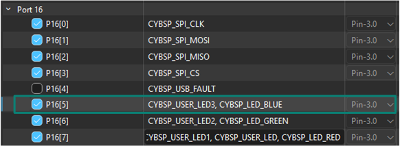
Click the checkbox to enable the pin. All pins have a default alias which is used as reference in the configuration structures and application code. You may optionally define a custom alias for your pin
When the pin is selected, use the
Parameters
pane to define the configurations for the pin like the drive mode, drive strength, and slew rate.
Figure 6.
Define the configurations in the Parameters pane
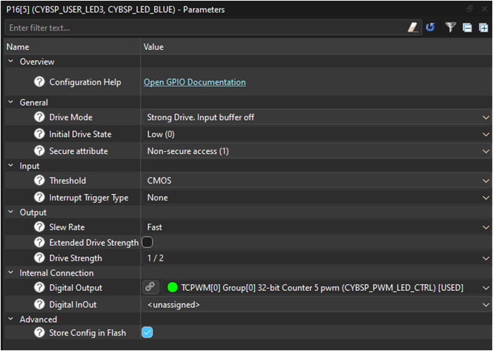
The pin is now enabled and set up with the desired configurations. You can use the same alias to use the pin
A GPIO can also be configured using PDL bypassing the Device Configurator. In this case, you will need to write your own configuration structure and use it in the application code. See the following code snippet for reference.
static const cy_stc_gpio_pin_config_t LED1_config =
{
    .outVal    = 0u,                      /* Start low (adjust to 1u if LED is active-low and you want it off) */
    .driveMode = CY_GPIO_DM_STRONG,       /* Push-pull output */
    .hsiom     = HSIOM_SEL_GPIO,          /* Route to GPIO function */
    .slewRate  = CY_GPIO_SLEW_FAST,       /* Optional: fast edge rate */
    .driveSel  = CY_GPIO_DRIVE_1_2,       /* Optional: 1/2 drive to reduce EMI/current */
    .nonSec    = 1u                       /* Mark pin as Non-Secure */
    /* All other fields left at default (0): interrupts disabled, default thresholds, etc. */
};
/* Initialize the LED pin with the configuration structure. */
Cy_GPIO_Pin_Init(CYBSP_USER_LED1_PORT, CYBSP_USER_LED1_PIN, &LED1_config);

/* Toggle the LED */
Cy_GPIO_Inv(CYBSP_USER_LED1_PORT, CYBSP_USER_LED1_PIN);
Examples for HAL usage with middleware
This section discusses the setup and usage of the new HAL with examples which are commonly used in PSOC™ Edge code examples.
Retarget-io setup (UART usage)
Retarget-io is a utility library to retarget the standard input/output (STDIO) messages to a UART port. With this library, you can directly print messages on a UART terminal using
printf()
. You can specify the TX pin, RX pin, and the baud rate when configuring the UART. See this library on GitHub:
.
You may refer to the
PSOC Edge MCU: Hello World
code example for a demonstration of using the UART HAL with the retarget-io middleware.
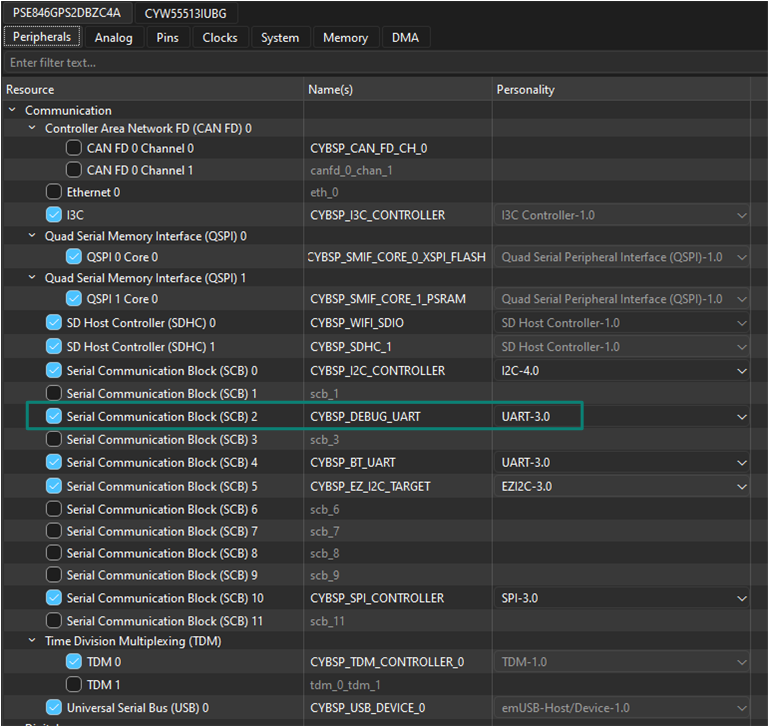
As the first step, enable the SCB2 peripheral under the
Peripherals
tab in the Device Configurator and select
UART
as the mode of operation. On PSOC™ Edge E84 evaluation kit, SCB2 is connected to the KitProg UART bridge. Note that the SCB2 peripheral is enabled by default and configured in the BSP with the alias
CYBSP_DEBUG_UART
as shown in the following figure
Figure 7.
SCB2 peripheral aliased and configured for UART operation
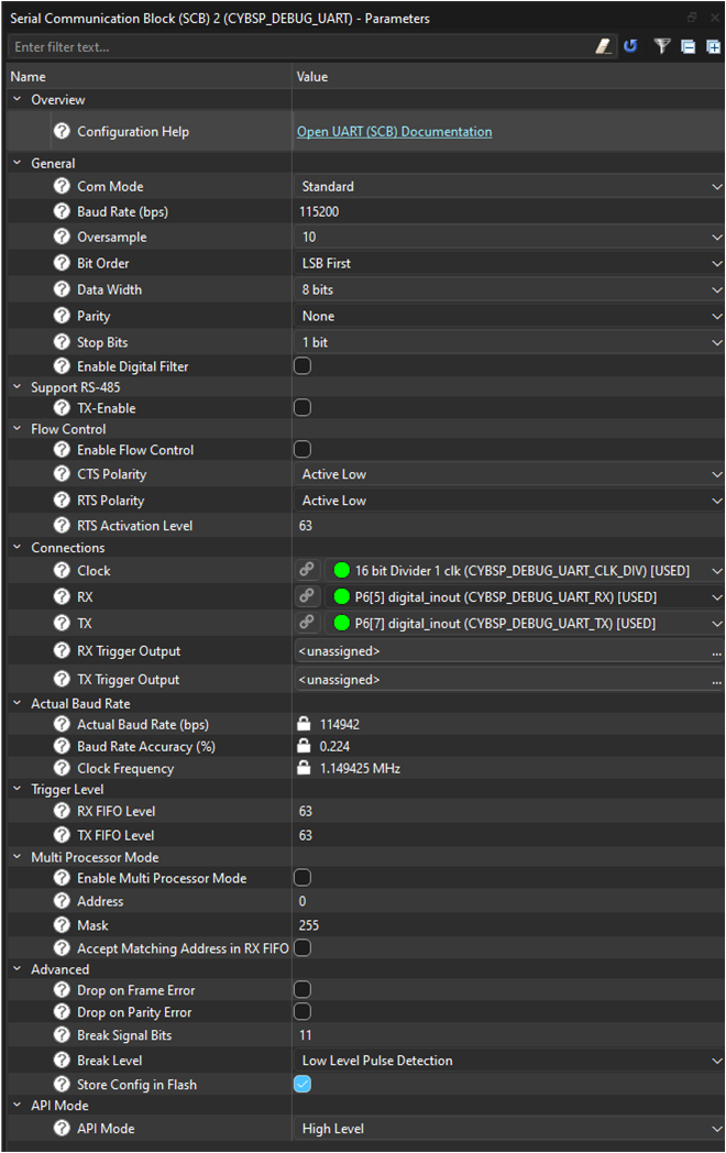
Configure the SCB2 block to be used as UART with the following set of configurations in the
Parameters
pane. Configuration includes the clock source configuration for the UART peripheral, UART TX and RX pins, CTS/RTS pins if flow control is desired, baud rate, and other UART config parameters
Figure 8.
UART configuration parameters
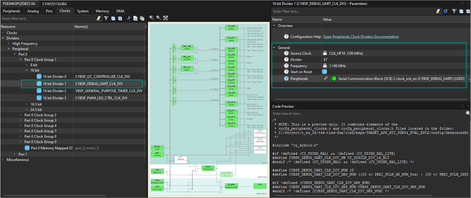
Set up the clock divider value depending on the desired baud rate in the
Clocks
tab as shown in the following figure. This setting is already configured with the 16-bit divider 1 clock divider in the default BSP
Figure 9.
UART clock divider
Import the 'retarget-io' middleware library using ModusToolbox™ Library Manager. See
1
on steps to add libraries to projects
Once imported, add #include "cy_retarget_io.h" inclusion in the application source file
Create and use the HAL object
DEBUG_UART_hal_obj
to set up the UART HAL and pass the same object to initialize the
retarget-io
middleware
Follow the steps as highlighted in the section Initialization sequence to initialize and set up the SCB UART
Initialize the SCB UART
result = (cy_rslt_t)Cy_SCB_UART_Init(CYBSP_DEBUG_UART_HW,
                                    &CYBSP_DEBUG_UART_config,
                                    &DEBUG_UART_context);

/* Check Result */
Enable the UART peripheral
Cy_SCB_UART_Enable(CYBSP_DEBUG_UART_HW);Set up the HAL UART object
result = mtb_hal_uart_setup(&DEBUG_UART_hal_obj,
                                &CYBSP_DEBUG_UART_hal_config,
                                &DEBUG_UART_context, NULL);
/* Check result */
Initialize the middleware using the HAL object
result = cy_retarget_io_init(&DEBUG_UART_hal_obj);
/* Check result */
If required, register a callback to handle the transitions to low-power modes. If the system idle power mode is set as Sleep or Deep Sleep, it is essential to register the
SysPm
callback for the peripheral. This can be done by registering with
Cy_SysPm_RegisterCallback
either the predefined callbacks from the
SysPm
callbacks under Device Utilities (device-utils) library or a new callback function specific to your application needs. This callback will manage the necessary procedures for the peripheral while transitioning in and out of low-power modes like Sleep or Deep Sleep gracefully. For more information, refer to
Cy_SysPm_RegisterCallback
in PDL documentation. See the
PSOC Edge MCU: Hello World
code example for SysPm callback implementation for the retarget-io middleware
Start printing to UART using
printf()
See the following code snippets for implementation details.
/* For the RetargetIO (Debug UART) usage. */
static cy_stc_scb_uart_context_t    DEBUG_UART_context;
static mtb_hal_uart_t               DEBUG_UART_hal_obj;
/* Retarget-io deepsleep callback parameters  */
#if (CY_CFG_PWR_SYS_IDLE_MODE == CY_CFG_PWR_MODE_DEEPSLEEP)

/* Context reference structure for Debug UART */
static mtb_syspm_uart_deepsleep_context_t retarget_io_syspm_ds_context =
{
    .uart_context       = &DEBUG_UART_context,
    .async_context      = NULL,
    .tx_pin =
    {
        .port           = CYBSP_DEBUG_UART_TX_PORT,
        .pinNum         = CYBSP_DEBUG_UART_TX_PIN,
        .hsiom          = CYBSP_DEBUG_UART_TX_HSIOM
    },
    .rts_pin =
    {
        .port           = DEBUG_UART_RTS_PORT,
        .pinNum         = DEBUG_UART_RTS_PIN,
        .hsiom          = HSIOM_SEL_GPIO
    }
};

/* SysPm callback parameter structure for Debug UART */
static cy_stc_syspm_callback_params_t retarget_io_syspm_cb_params =
{
    .context            = &retarget_io_syspm_ds_context,
    .base               = CYBSP_DEBUG_UART_HW
};

/* SysPm callback structure for Debug UART */
static cy_stc_syspm_callback_t retarget_io_syspm_cb =
{
    .callback           = &mtb_syspm_scb_uart_deepsleep_callback,
    .skipMode           = SYSPM_SKIP_MODE,
    .type               = CY_SYSPM_DEEPSLEEP,
    .callbackParams     = &retarget_io_syspm_cb_params,
    .prevItm            = NULL,
    .nextItm            = NULL,
    .order              = SYSPM_CALLBACK_ORDER
};
#endif /* (CY_CFG_PWR_SYS_IDLE_MODE == CY_CFG_PWR_MODE_DEEPSLEEP) */
void init_retarget_io(void)
{
    cy_rslt_t result = CY_RSLT_SUCCESS;

    /* Initialize the SCB UART */
    result = (cy_rslt_t)Cy_SCB_UART_Init(CYBSP_DEBUG_UART_HW,
                                        &CYBSP_DEBUG_UART_config,
                                        &DEBUG_UART_context);

    /* UART initialization failed. Stop program execution. */
    if (CY_RSLT_SUCCESS != result)
    {
        handle_app_error();
    }

    /* Enable the SCB UART */
    Cy_SCB_UART_Enable(CYBSP_DEBUG_UART_HW);

    result = mtb_hal_uart_setup(&DEBUG_UART_hal_obj,
                                &CYBSP_DEBUG_UART_hal_config,
                                &DEBUG_UART_context, NULL);

    /* UART setup failed. Stop program execution. */
    if (CY_RSLT_SUCCESS != result)
    {
        handle_app_error();
    }

    /* Initialize retarget-io to use the debug UART port. */
    result = cy_retarget_io_init(&DEBUG_UART_hal_obj);

    /* retarget-io initialization failed. Stop program execution. */
    if (CY_RSLT_SUCCESS != result)
    {
        handle_app_error();
    }

#if (CY_CFG_PWR_SYS_IDLE_MODE == CY_CFG_PWR_MODE_DEEPSLEEP)
    /* UART SysPm callback registration for retarget-io */
    Cy_SysPm_RegisterCallback(&retarget_io_syspm_cb);
#endif /* (CY_CFG_PWR_SYS_IDLE_MODE == CY_CFG_PWR_MODE_DEEPSLEEP
BMI 270 motion sensor (I2C usage)
The BMI270 inertial measurement unit (IMU) motion sensor library provides functions for interfacing with the Bosch BMI270 I2C 16-bit inertial measurement unit (IMU) with 3-axis accelerometer and 3-axis gyroscope. The sensor-motion-bmi270 is a middleware library and can be set up to be used with the new HAL workflow. The Bosch BMI270 sensor is available on the PSOC™ Edge E84 Evaluation Kit and is interfaced to the MCU through I2C (SCB0). The same sensor may connect to some other I2C instance on a different evaluation board. See the board documentation for details. See this library on GitHub:
.
You may refer to the
PSOC Edge MCU: Sensor hub data acquisition
code example for a demonstration of using the I2C HAL with the BMI 270 motion sensor library.
As the first step, enable the SCB0 peripheral under the
Peripherals
tab in the Device Configurator and select
I2C
as the mode of operation. Note that the SCB0 peripheral is enabled by default and configured in the BSP with the alias
CYBSP_I2C_CONTROLLER
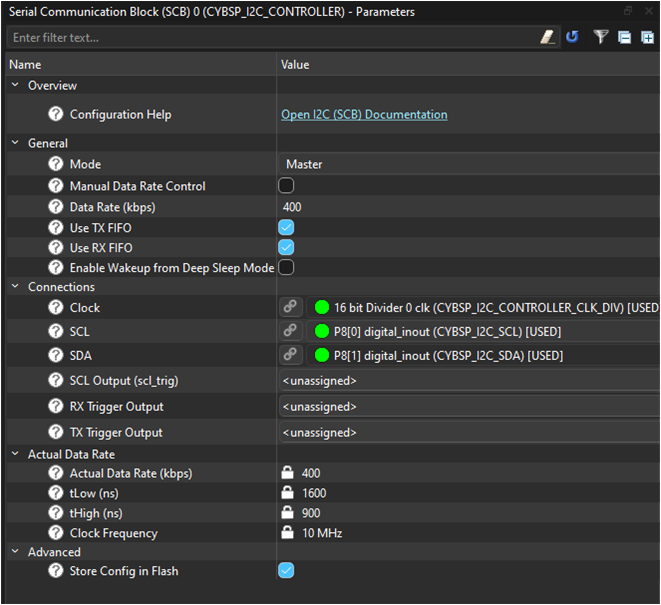
Configure the SCB2 block to be used as I2C with the following set of configurations in the
Parameters
pane. Configurations include the I2C mode, data rate, Clock , SCL and SDA connections
Figure 10.
I2C configuration parameters
Import the
sensor-motion-bmi270
middleware library using ModusToolbox™ Library Manager. See
1
on steps to add libraries to projects
Once imported, Add #include "mtb_bmi270.h" inclusion in the application source file
Create and use the
CYBSP_I2C_CONTROLLER_hal_obj
HAL object to set up the I2C HAL and pass the same object to initialize the
sensor-motion-bmi270
middleware
Follow the steps as highlighted in the section "Initialization sequence" to initialize and set up SCB I2C
Initialize SCB I2C
initStatus = Cy_SCB_I2C_Init(CYBSP_I2C_CONTROLLER_HW,
                                &CYBSP_I2C_CONTROLLER_config,
                                &CYBSP_I2C_CONTROLLER_context);
/* Check result */
Enable the I2C peripheral
Cy_SCB_I2C_Enable(CYBSP_I2C_CONTROLLER_HW);Set up the HAL I2C object
result = mtb_hal_i2c_setup(&CYBSP_I2C_CONTROLLER_hal_obj,
                                &CYBSP_I2C_CONTROLLER_hal_config,
                                &CYBSP_I2C_CONTROLLER_context,
                                NULL);
/* Check result */
Initialize the middleware using the HAL object
result = mtb_bmi270_init_i2c(&bmi270,
                                &CYBSP_I2C_CONTROLLER_hal_obj,
                                MTB_BMI270_ADDRESS_DEFAULT);
/* Check result */
Configure the sensor and use it in the application code
See the following code snippets for implementation details.
/* HAL objects for sensor-motion-bmi270 library. */
static mtb_hal_i2c_t CYBSP_I2C_CONTROLLER_hal_obj;
cy_stc_scb_i2c_context_t CYBSP_I2C_CONTROLLER_context;
{
 initStatus = Cy_SCB_I2C_Init(CYBSP_I2C_CONTROLLER_HW,
                                &CYBSP_I2C_CONTROLLER_config,
                                &CYBSP_I2C_CONTROLLER_context);
    /* I2C initialization failed. Stop program execution. */
    if (CY_SCB_I2C_SUCCESS != initStatus)
    {
        handle_app_error();
    }
    Cy_SCB_I2C_Enable(CYBSP_I2C_CONTROLLER_HW);
    result = mtb_hal_i2c_setup(&CYBSP_I2C_CONTROLLER_hal_obj,
                                &CYBSP_I2C_CONTROLLER_hal_config,
                                &CYBSP_I2C_CONTROLLER_context,
                                NULL);
    /* HAL I2C setup failed. Stop program execution. */
    if (CY_RSLT_SUCCESS != result)
    {
        handle_app_error();
    }
    /* Initialize can configure platform-dependent function pointers. */
    result = mtb_bmi270_init_i2c(&bmi270,
                                &CYBSP_I2C_CONTROLLER_hal_obj,
                                MTB_BMI270_ADDRESS_DEFAULT);

    /* BMI270 sensor initialization failed. Stop program execution. */
    if (CY_RSLT_SUCCESS != result)
    {
        handle_app_error();
    }
}
LPTimer setup for use with abstraction RTOS library
The RTOS abstraction layer provides a simple RTOS-agnostic implementation of common RTOS services such as threads, semaphores, mutexes, queues, and timers. See this library on GitHub:
.
For PSOC™ Edge code examples based on FreeRTOS, the tickless idle mode must be implemented for power saving in Deep Sleep by setting up the LPTimer instance in the application. The RTOS interface will be treated as a middleware. An HAL object will be passed to the abstraction RTOS library. In this example, the LPTimer instance is set up for the CM33 CPU. A similar setup must be done on the CM55 side using another instance of LPTimer.
You may refer to the
PSOC Edge MCU: Empty application
code example for a demonstration of using the LPTimer with the BMI 270 motion sensor library.
As the first step, enable the Multi-Counter Watchdog TImer (MCWDT) 0 peripheral under the
Peripherals
tab in the Device Configurator. Note that the MCWDT0 peripheral is enabled by default and configured in the BSP Device Configurator with the alias
CYBSP_CM33_LPTIMER_0
. MCWDT0 instance is meant to be used with CM33 CPU while the MCWDT1 instance should be used with CM55 CPU as also indicated by the alias
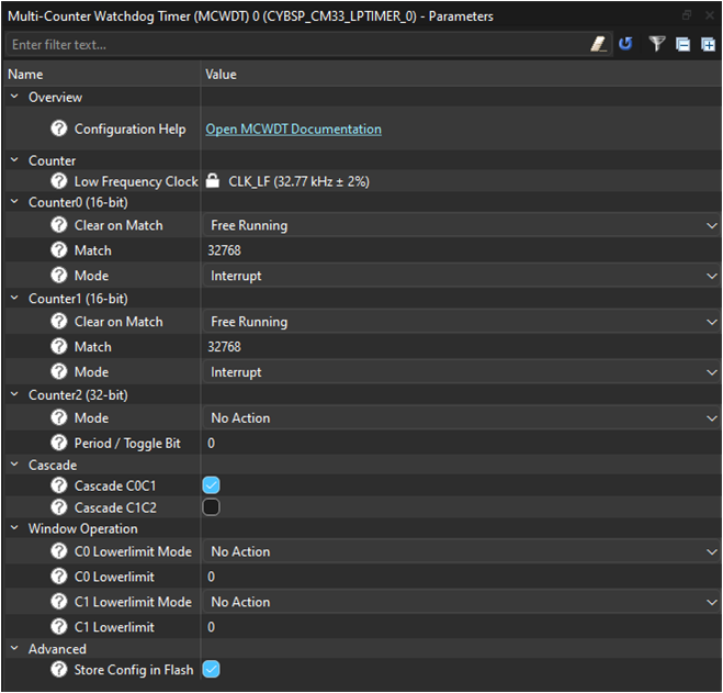
Configure the MCWDT0 block with the following set of configurations in the
Parameters
pane:
Figure 11.
LPTimer configuration parameters
The
abstraction-rtos
middleware library is a dependent library for the
FreeRTOS
middleware library. It is therefore automatically fetched when
FreeRTOS
is added to the code example. See
1
on steps to add libraries to projects
Include the header files for the
abstraction-rtos
library in the application source file: - #include "cyabs_rtos.h"
Create and use the HAL object
lptimer_obj
to set up the LPTimer HAL and pass the same object to initialize the
abstraction-rtos
middleware
Follow the steps as highlighted in the "Initialization sequence" section to initialize and set up the
LPTimer0
instance
Initialize the LPTimer interrupt and interrupt handler as necessary
/* Interrupt configuration structure for LPTimer */
cy_stc_sysint_t lptimer_intr_cfg =
{
    .intrSrc = CYBSP_CM33_LPTIMER_0_IRQ,
    .intrPriority = APP_LPTIMER_INTERRUPT_PRIORITY
};

/* Initialize the LPTimer interrupt and specify the interrupt handler. */
cy_en_sysint_status_t interrupt_init_status =
                                Cy_SysInt_Init(&lptimer_intr_cfg,
                                                lptimer_interrupt_handler);

/* LPTimer interrupt initialization failed. Stop program execution. */
if(CY_SYSINT_SUCCESS != interrupt_init_status)
{
    handle_app_error();
}
Initialize the MCWDT0 peripheral block
/* Initialize the MCWDT block */
cy_en_mcwdt_status_t mcwdt_init_status =
                                Cy_MCWDT_Init(CYBSP_CM33_LPTIMER_0_HW,
                                            &CYBSP_CM33_LPTIMER_0_config);

/* MCWDT initialization failed. Stop program execution. */
if(CY_MCWDT_SUCCESS != mcwdt_init_status)
{
    handle_app_error();
}
Enable the MCWDT0 instance
/* Enable MCWDT instance */
Cy_MCWDT_Enable(CYBSP_CM33_LPTIMER_0_HW,
                CY_MCWDT_CTR_Msk,
                LPTIMER_0_WAIT_TIME_USEC);
Set up the LPTimer HAL object
* Setup LPTimer using the HAL object and desired configuration as defined
* in the device configurator. */
cy_rslt_t result = mtb_hal_lptimer_setup(&lptimer_obj,
                                        &CYBSP_CM33_LPTIMER_0_hal_config);

/* LPTimer setup failed. Stop program execution. */
if(CY_RSLT_SUCCESS != result)
{
    handle_app_error();
}
Initialize the middleware using the HAL object
/* Pass the LPTimer object to abstraction RTOS library that implements
* tickless idle mode */
cyabs_rtos_set_lptimer(&lptimer_obj);
LPTimer is now set up to enable tickless idle mode
See the following code snippet for implementation details.
/* LPTimer HAL object */
static mtb_hal_lptimer_t lptimer_obj;
static void lptimer_interrupt_handler(void)
{
    mtb_hal_lptimer_process_interrupt(&lptimer_obj);
}
static void setup_tickless_idle_timer(void)
{
    /* Interrupt configuration structure for LPTimer */
    cy_stc_sysint_t lptimer_intr_cfg =
    {
        .intrSrc = CYBSP_CM33_LPTIMER_0_IRQ,
        .intrPriority = APP_LPTIMER_INTERRUPT_PRIORITY
    };

    /* Initialize the LPTimer interrupt and specify the interrupt handler. */
    cy_en_sysint_status_t interrupt_init_status =
                                    Cy_SysInt_Init(&lptimer_intr_cfg,
                                                    lptimer_interrupt_handler);

    /* LPTimer interrupt initialization failed. Stop program execution. */
    if(CY_SYSINT_SUCCESS != interrupt_init_status)
    {
        handle_app_error();
    }

    /* Enable NVIC interrupt. */
    NVIC_EnableIRQ(lptimer_intr_cfg.intrSrc);

    /* Initialize the MCWDT block */
    cy_en_mcwdt_status_t mcwdt_init_status =
                                    Cy_MCWDT_Init(CYBSP_CM33_LPTIMER_0_HW,
                                                &CYBSP_CM33_LPTIMER_0_config);

    /* MCWDT initialization failed. Stop program execution. */
    if(CY_MCWDT_SUCCESS != mcwdt_init_status)
    {
        handle_app_error();
    }

    /* Enable MCWDT instance */
    Cy_MCWDT_Enable(CYBSP_CM33_LPTIMER_0_HW,
                    CY_MCWDT_CTR_Msk,
                    LPTIMER_0_WAIT_TIME_USEC);

    /* Setup LPTimer using the HAL object and desired configuration as defined
     * in the device configurator. */
    cy_rslt_t result = mtb_hal_lptimer_setup(&lptimer_obj,
                                            &CYBSP_CM33_LPTIMER_0_hal_config);

    /* LPTimer setup failed. Stop program execution. */
    if(CY_RSLT_SUCCESS != result)
    {
        handle_app_error();
    }

    /* Pass the LPTimer object to abstraction RTOS library that implements
     * tickless idle mode */
    cyabs_rtos_set_lptimer(&lptimer_obj);
}
Summary
This guide introduces Infineon’s redesigned Hardware Abstraction Layer (HAL) for PSOC™ Edge and how to use it effectively. The new HAL is streamlined and middleware-focused; therefore, you should not use it directly in an application. Device setup, resource management, pins, clocks, and higher-level configuration are handled explicitly by the Peripheral Driver Library (PDL) and the Device Configurator, with device-specific details centralized in a device support library. The redesign clarifies layering, separates configuration from initialization, moves device-dependent behavior down to PDL, thereby improving transparency, predictability, and debuggability. HAL’s role is to support portability and a consistent API for middleware once the hardware is already configured.
References
Infineon Technologies AG:
AN235935 - Getting started with PSOC™ Edge E8 MCU on ModusToolbox™ software
;
Available online
Revision history
Document revision | Date | Description of changes |
|---|---|---|
** | 2025-10-14 | Initial release |
Trademarks
The Bluetooth® word mark and logos are registered trademarks owned by Bluetooth SIG, Inc., and any use of such marks by Infineon is under license.
PSOC™, formerly known as PSoC™, is a trademark of Infineon Technologies. Any references to PSoC™ in this document or others shall be deemed to refer to PSOC™.