AN237849 Getting started with PSOC™ Edge security
About this document
Scope and purpose
This getting started guide provides information on how to get started with security on the PSOC™ Edge MCU out of the box. It contains guidance on how to provision and program a secure application. It introduces the security architecture of the PSOC™ Edge MCU, consisting of a low power, lock-step Secure Enclave that protects the device root of trust, an Arm® TrustZone enabled Cortex®-M33 and a non-secure Cortex®-M55 core. This document also provides a brief overview of other security features available on the device.
Intended audience
This is an introductory document for getting started with PSOC™ Edge MCU security.
Overview of PSOC™ Edge MCUs
The PSOC™ Edge MCU is a multicore device that contains two CPUs (Cortex®-M33 and Cortex®-M55), nonvolatile onboard storage, a range of peripherals, including ADC, UART, SPI, I2C, I3C, PWM, SMIF, crypto accelerators, and several other blocks. Each device also includes a Secure Enclave (SE), which includes two additional Cortex®-M0+ CPUs that operate in delayed lock-step mechanism.
The Secure Enclave is responsible for the initial secure boot and the root of trust. It also provides a range of security functions, maintains storage for secure keys, and performs security key management. Communication with the Secure Enclave is via an IPC channel only. The Secure Enclave will only run code that has been signed by Infineon. Its code and data reside within the Secure Enclave and are not accessible by the other CPUs or DMA channels. OEMs cannot develop or inject their code into the Secure Enclave. The Secure Enclave run-time services (SERT) library that runs on the Secure Enclave may be updated, but the update must be signed by Infineon, as well as the module that installs the update.
The other two CPUs, CM33 and CM55, are fully accessible by the user application. The CM33 supports Arm® TrustZone that allows for both a secure programming environment (SPE) and a non-secure programming environment (NSPE). Although a single CPU is used, individual SPE and NSPE projects may be created. The CM55 is the highest-performance CPU and is intended to run most of the developer’s applications. Both the CM33 and CM55 have access to most of the same peripheral blocks, so the developer can pick and choose what functions and hardware blocks are controlled by the two CPUs (CM33 and CM55).
Figure 1
shows the basic programming environment, not including the peripherals. As mentioned above, the user application may only run on the CM33 or CM55 CPUs.
Figure 1.
CPU memory view
Code may be stored locally in internal RRAM or on an external flash device. Code execution may run directly from the non-volatile memory (NVM) location in which it was stored or, at run-time, be moved to a different location to enhance performance. For example, the CM55 may execute code from external flash, internal RRAM, system SRAM (SoCMEM), or ITCM. If executing in system SRAM (SoCMEM) or ITCM, it must be copied to that location as part of the start-up firmware.
There are two categories of parts in this family, the EPC 2 and the EPC 4 parts. These parts are compliant to the Edge Protect categories 2 and 4 as described
here
. Both EPC 2 and EPC 4 parts support secure boot, secure firmware update services and secured debug services
To achieve highest levels of security supported by PSOC™ Edge, it is recommended to use the EPC 4 part which contains the Secure Enclave run-time services (SE RT) library for Platform Security Architecture (PSA) complaint root of trust (RoT) services such as secured cryptographic services, secured key storage, attestation, and more. This part also supports the large profile Trusted Firmware-M (TF-M) features and is DICE compliant.
The SE RT services library is not available on an EPC 2 device which frees up space in the internal RRAM memory for user application. These parts support Trusted Firmware-M (TF-M ) medium profile. In these parts, user cannot access the DICE and ALIAS private keys stored in the protected region, the ALIAS key pair is copied to the NVM region as IAK_LITE key pair during the device manufacturing, and can be used for PSA initial attestation.
For features supported by EPC 2 and EPC 4 parts, refer to the
Security features of EPC 2 and EPC 4 category parts
section.
Note:
See ordering information in the product datasheet for EPC 2 and EPC 4 part numbers.
Ease of development
Device life cycle stage (LCS)
There are three device life cycle stages that are important to the product developer:
Development
Production
Return merchandise authorization (RMA)
Devices are shipped in the development stage that allows the device to be provisioned and programmed as many times as needed to develop the final application. Devices are shipped with a default policy that defines all debug ports as open and code authorization as disabled. This allows any user to program, evaluate, and debug the parts prior to any knowledge about security or code signing.
During the development stage, the OEM may take ownership of the part. This will allow the owner to replace the default policy file with a custom policy. All aspects of the production stage may be simulated, including locking down the CPU access ports that will lock out any attempt to connect the debugger to the part. The only difference between the development and production stages from a code operation point of view is that the SYS_AP (system access port) cannot be disabled in the development stage. This ensures that the developer cannot be locked out of the part and can, at any time, recover from a device configuration error and even return the device to its original state.
When the firmware is ready for production, the device may be advanced to the production stage. The production stage locks down the owner of the device, meaning that the key used to authenticate the firmware can no longer be changed from what was programmed into the device. The debug ports, including SYS_AP, can all be disabled or left enabled as per user requirement.
Devices may be advanced to the production stage upon receiving them from Infineon. This is the typical model once the OEM starts to ship their product. There is no need to transfer ownership in the development stage; instead, the user may take ownership and advance the device to the Production stage in a single step as part of provisioning the device.
Note:
For PSA L4 compliance, the device shall be transitioned to Production LCS with all debug ports closed before shipping out of the OEM factory. Alternatively, debug ports shall be enabled for authenticated access only.
The RMA stage is only used in the event that a problem is found in the hardware and the device must be shipped back to Infineon for failure analysis.
Figure 2
shows the flow from Development to RMA.
Figure 2.
Device life cycle flow
Development flow
The typical development flow for any embedded project is:
Modifying your project code
Compile/link
Program the device
Run/debug on the device
The PSOC™ Edge device typically follows the same workflow as most other systems. The main difference is that device ownership may be transferred or the policy may be changed before or in between development cycles. Once this is done, the standard flow can be resumed.
Figure 3.
Development flow
Transfer of ownership
Ownership of the device belongs to the one who owns the private/public keys that are used to sign and authenticate the application code and the policy file. When the PSOC™ Edge parts leave Infineon, the default owner is Infineon. The default policy file configures the debug ports to be open and does not require code signing, so anyone can download and debug code without performing any additional action. Once ownership has been 'transferred', the policy file must be signed by the owner of the device, or the device will not boot. If you want to change something in the policy file, such as enabling code signing or changing the location of the first code, then you must also 'transfer ownership' to yourself because the policy file must be signed by the owner.
The process of transferring ownership from Infineon to the OEM (user) only needs to occur once, but there is no limit to how many times ownership is transferred while the device is in the 'development' life cycle stage (LCS). This allows a device or development kit to be evaluated by several different people without having to remember or share security keys. Note that the device leaves Infineon in the development LCS.
Figure 4.
Ownership transfer
Getting started
If at first you just want to evaluate the part and not sign code or change the policy file, there is no need to use any special commands. Even without transferring ownership, you can still evaluate the device and have access to all security libraries and hardware.
General application development instructions are available in the "Application development instructions" section of the
AN235935 - Getting started with PSOC™ Edge E8 on ModusToolbox™ software
document.
For getting started with security, it is recommended to use the
PSOC™ Edge Basic Secure App
code example. You can start using this code example out of the box without applying any additional security, as the default OEM policy disables the 'secure boot' feature of the Extended Boot. See the next sections for instructions on how to start using security.
The first step towards making any changes to the policy file is to transfer the ownership.
Once you are ready to transfer ownership to yourself, there are a few things that you need to do:
Initialize application directory for Edge Protect Tools
Generate OEM key pair (private/public)
Edit policy file (optional)
Create OEM_CERT certificate and have it signed by Infineon
Sign policy file (even if you have not changed it)
Infineon Edge Protect Tools (EPT) is a set of command-line tools used to perform the needed functions for key signing, key generation, creating OEM certificate, provisioning the device, and so on. Edge Protect Tools is available as part of the Edge Protect Security Suite which must be installed in your system along with the ModusToolbox™ installation package.
Pre-compiled executable binary file for the tools is available for easy use and can be located in the
C:/Users/<username>/Infineon/Tools/ModusToolbox-Edge-Protect-Security-Suite-1.6/tools/edgeprotecttools/bin
directory. Add the path to this executable to the system environment PATH variable of the host PC and move it to the top of the list to use this tool from the shell command line. It is recommended to use 'modus-shell' that is installed along with ModusToolbox™. Modus-shell is installed in the
ModusToolbox/tools_x.y
directory.
Note:
Ensure that the KitProg3 on your PSOC™ Edge device is updated to firmware version 2.60.1412 or later. More information about KitProg3 is available in the
AN235935 - Getting started with PSOC™ Edge E8 on ModusToolbox™ software
document.
Initialize the application directory
Initializing the application folder for Infineon Edge Protect Tools, creates additional folders in your application directory. The following is a list of these folders and their contents.
keys: Any keys that you create with the Edge Protect Tools will be placed in this directory. If you prefer to create your own keys, they should also be placed in this directory
logs: Each time you run Edge Protect Tools, a time and date log file are created. These files can assist in debugging any problems with the tools that may occur. This directory is created the first time that you execute an Edge Protect Tools command after initialization
packets: Some commands generate CBOR formatted packets that are downloaded into the device or will be used by another command. These files are placed in this folder
policy: This folder contains some sample policy files that can be modified or copied as needed. Eventually, each user will have a custom policy file that fits their application
Open modus-shell and navigate to the top level of your ModusToolbox™ application directory. This will be the same level as the application project directories.
$ cd <application directory>
The following command will initialize the application directory and prepare it for all the following Edge Protect Tools commands. Execute this only once per application. Additionally, execute this command whenever a new version of Edge Protect Tools is installed.
$ edgeprotecttools -t pse8xs2 init
Note:
During development LCS, you can execute the
init
command whenever it is required to revert any custom configuration or file modifications done to the Edge Protect Tools project in the application directory. This command will reinitialize the Edge Protect Tools to default configuration/settings for the specific target.
Note:
Two targets are supported for PSOC™ Edge by Edge Protect Tools:
pse8xs2
for the EPC 2 device
pse8xs4
for the EPC 4 device
This document uses
pse8xs2
target for demonstration. User should select the target that matches the device being used for their application.
The below command should be executed once per session to configure the connection between the tool and a MiniProg4 or KitProg3 USB port.
$ edgeprotecttools set-ocd --name openocd --path <openocd_path>
Replace
<openocd_path>
with the path to the
openocd
directory . Typically, this will be
C:/Infineon/Tools/ModusToolboxProgtools-1.5/openocd
.
Note:
To configure Edge Protect Tools to use the serial interface, see the
Alternate serial interface
section.
Key generation
You need to create a key pair (private and public key). The following command generates one pair of keys that will be placed in the keys directory.
$ edgeprotecttools create-key --key-type ECDSA-P256 --output keys/oem_private_key_0.pem keys/oem_public_key_0.pem
The key generated is a 256-bit ECC key output in a
.pem
format. This is a common ASCII format compatible with many public domain tools.
Note:
User can create either one or two OEM RoT key pairs to be used for provisioning. For production lifecycle, user must provision two pairs of OEM RoT keys into the device.
Command option | Example parameter | Description |
|---|---|---|
| ECDSA-P256 | Key type of the generated key |
, | keys/oem_private_key_0.pem | Path where generated key is stored |
OEM certificate creation
This step creates a certificate signing request (CSR). A CSR contains information about the OEM-certificate such as the certificate type (development or production), the OEM ROT public keys, the OEM name, and project information. The CSR should be signed by the OEM ROT private key. The OEM-signed CSR must then be submitted to Infineon to generate the Infineon signed OEM certificate.
This step is required every time when the OEM provisions a new set of OEM ROT keys to the device. Typically, it is required once in development LCS (transfer of ownership) and once when transitioning to production LCS.
The following command creates an OEM signed CSR for development LCS that can be submitted to Infineon to create an Infineon signed OEM certificate (OEM_CERT).
$ edgeprotecttools -t pse8xs2 oem-csr --certificate-name "oem-cert" --oem "Dummy OEM" --project "Dummy Project" --project-number "1234" --public-key-0 keys/oem_public_key_0.pem --cert-type development --output packets/apps/prov_oem/oem_csr.bin --sign-key-0 keys/oem_private_key_0.pem
Command option | Example parameter | Description |
|---|---|---|
| packets/apps/prov_oem/oem_csr.bin | Path where output CSR is stored |
| "oem-cert" | Name of the certificate |
| "Dummy OEM" | Name of the OEM |
| "Dummy Project" | Name of the project associated with the certificate |
--project-number | "1234" | Project number associated with the certificate |
| keys/oem_public_key_0.pem | OEM ROT Public Key |
| keys/oem_private_key_0.pem | Private key associated with the |
| development/production | The certificate type determines the LCS of the device. It can be either development or production LCS |
Once the CSR is created, it must be signed by Infineon to create a valid OEM certificate.
Follow these steps outlined to generate an Infineon signed OEM certificate.
Prior to creating a certificate, you must sign up for an Infineon online software tools and services (OSTS) account. Any developer may create an OSTS account by registering at
osts.infineon.com
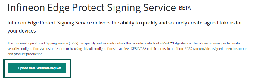
Once you have registered, login to your OSTS account and click on
Edge Protect Signing Service
. This will take you to a page where you can upload your Certificate Signing Request (CSR) that you created in the previous step. Click on the
Upload New Certificate Request
button. This will take you to a window where you can upload your CSR, enter a name for the certificate, and enter a description
Figure 5.
Upload new certificate request
Enter the certificate name without any spaces or special characters, if you enter the name as
“oem”
, the generated certificate will be named
“oem_cert.bin”
. Select the silicon revision as
PSOC™ Edge E84 Rev.B0
. Next, enter the description for this certificate in the “Description” field. This description will be in the list of certs that you own, so you can easily identify one cert from another if you have more than one
Click the
Drop file here or click to upload
button to upload the CSR and navigate to the CSR that you created in the previous step instead of dropping the file in this area. In the previous steps, the path was
packets/apps/prov_oem/oem_csr.bin
Figure 6.
Uploading CSR
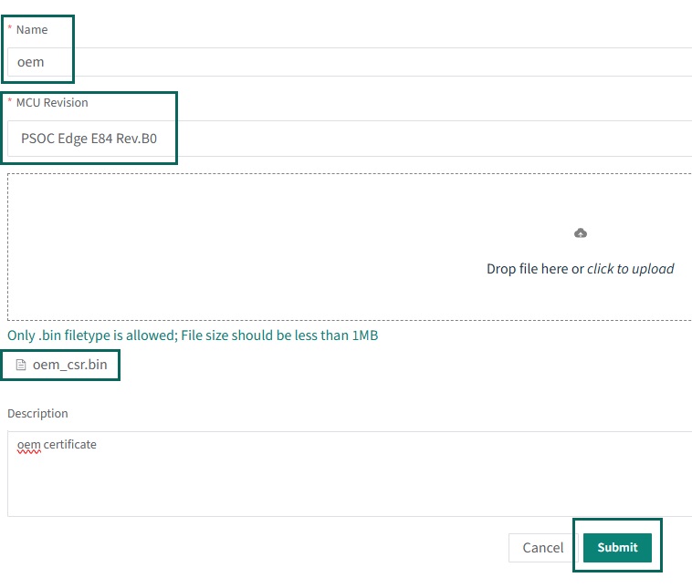
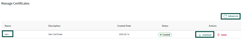
Once the name and description have been entered and the CSR has been uploaded, click the
Submit
button. This should take you back to the original page with a list of certificates under
Manage Certificates
. If the list does not show the most recent certificate generated, click on the
Refresh List
. You should now see the signed certificate ready for you to download. Click on the
Download
button on the line that contains the certificate you want to download. This will download the signed certificate to the location on your computer where the files are downloaded. Copy the certificate to the path
packets/apps/prov_oem/oem_cert.bin
Figure 7.
Manage certificates
You can revisit this website at any time and download any of the certificates that have been signed in the past.
During development, you only need to perform these steps once, but you can generate multiple certificates if needed.
Provisioning and the policy file
The default OEM_Policy file and OEM_ROT_PUBLIC_KEY are stored in the device before leaving the Infineon factory. The OEM_Policy file is configured such that all debug ports are open and the OEM code does not need to be signed. This allows the user to program and debug the device without restrictions. These default files are intended to be replaced by the OEM during development. These files must be replaced to eventually advance to the production stage.
Provisioning by the OEM occurs any time when the user takes ownership of the device and/or updates the policy file. The policy file is used to set boot parameters and define keys that the OEM wants to store in the device prior to shipment. During the development stage, the policy file may be updated as frequently as needed. The policy file is a text-editable file in JSON format. It is recommended to reuse the original policy file the first time you take ownership of the device to verify that you are still able to program the device in case of an error. The user-settable parameters in the policy file include the following:
Flag to authenticate the first OEM code or not
First OEM code location
Alternate OEM code location
CM33 CPU boot clock speed
Configuration of debug ports
Keys to be loaded into the device
The default policy file
policy_oem_provisioning.json
(OEM_Policy) is stored in the
<application directory>/policy
directory that was created when the application directory was initialized with
edgeprotecttools
. In order for the provisioning process to install a new OEM_Policy, it must be signed by the OEM_ROT_PRIVATE_KEY. Even during the Development stage, the OEM_Policy must be signed. More detail on the structure of the policy file and a description of the parameters are provided in the
Policy file
.
Any time ownership is transferred, the policy file must be signed by the new OEM_ROT_KEY (private). The following command changes ownership and updates the policy file.
$ edgeprotecttools -t pse8xs2 provision-device -p policy/policy_oem_provisioning.json --key keys/oem_private_key_0.pem --ifx-oem-cert packets/apps/prov_oem/oem_cert.bin
If ownership has already been transferred and you only want to update the policy file, you can leave the --ifx-oem-cert option, as shown below.
$ edgeprotecttools -t pse8xs2 provision-device -p policy/policy_oem_provisioning.json --key keys/oem_private_key_0.pem
provides the usage of each of the command-line parameters.
Command option | Example parameter | Description |
|---|---|---|
| policy/policy_oem_provisioning.json | This is the policy that is being used to provision with. You may start with the default and edit as needed |
| keys/oem_private_key_0.pem | This should be the initial OEM private key. It is used to sign the policy file. It must be the private key associated with the initial public key that was added to the oem-cert. |
| packets/apps/prov_oem/oem_cert.bin | This is the Infineon signed certificate that was created in the previous step. This option is not required if ownership has already been transferred and only the policy file is being updated |
See
AN238041 - PSOC™ Edge provisioning specification
for more information on the provisioning process.
See the
Appendix
section of this document for more details on the policy fields.
Enable secure boot by Extended Boot
Secure boot of the first OEM application by the Extended Boot can be enabled through the OEM policy file configuration. When the 'secure_boot' flag in the policy is enabled, Extended Boot will always verify the signature of the application that it boots, which is the first OEM code. The default policy in the PSOC™ Edge device disables the 'secure_boot' flag that means that for out-of-the-box use, Extended Boot does not verify the signature of the first OEM code.
To enable or disable the "secure_boot" in policy, you have to edit the OEM policy, which is a JSON file that can be located in the
<application directory>/policy/policy_oem_provisioning.json
path once you have initialized the Edge Protect Tools. See
Initialize the application directory
section for more details.
Set the "secure_boot" value to "true" in the extended_boot_policy.
"extended_boot_policy": (
    "secure_boot": (
      "description": "Disable/Enable secure boot option",
      "value": true
    ),
After making the required changes to the policy file, provision the device with the updated policy.
$ edgeprotecttools -t pse8xs2 provision-device -p policy/policy_oem_provisioning.json --key keys/oem_private_key_0.pem
Note:
As a prerequisite, follow the steps mentioned in the
Getting started
section to generate your keys and certificate and provision the device to transfer ownership.
Signing user application
The first OEM application must always be in MCUboot format to be successfully launched by the Extended Boot software. When using the default OEM policy, which has 'secure_boot' flag disabled, the first OEM application can be converted into the MCUboot format using the following command. This command adds only the MCUboot header.
$ edgeprotecttools image-metadata --image userapp.hex --output userapp_mcuboot.hex
Note:
Use
edgeprotecttools image-metadata --help
for command options.
provides the usage for each of the command-line parameters.
Command option | Example parameter | Description |
|---|---|---|
/ | userapp.hex | Input path to the user application |
/ | userapp_mcuboot.hex | Path where the application image with metadata should be saved |
Once the device has been provisioned with an OEM policy that enables 'secure_boot' flag, the signature of the first OEM application will be authenticated by the Extended Boot before launching the application.
The following command can be used to sign an application image. This command adds both the MCUboot header and signature.
$ edgeprotecttools sign-image -s 1 --image userapp.hex --output userapp_signed.hex --key keys/oem_private_key_0.pem
Note:
Use
"edgeprotecttools sign-image --help"
for command options.
Command option | Example parameter | Description |
|---|---|---|
/ | userapp.hex | Input path to the user application |
/ | userapp_signed.hex | Path where the application image with signature should be saved |
/ | keys/oem_private_key_0.pem | This should be the initial OEM private key. It is used to sign the user application. It must be the private key associated with the initial public key that was added to the oem-cert |
| 1 | This is the secure counter value for the application. The value should be >=1 |
Postbuild signing using ModusToolbox™ application
If you are working on a PSOC™ Edge ModusToolbox™ code example, such as the
Basic Secure App
, then the first user application is the CM33 SPE project (proj_cm33_s).
The MCUboot format image-metadata is added to the CM33 SPE image as a default configuration of the code example for the 'secure_boot' disabled policy.
When the 'secure_boot' is enabled in the OEM_Policy, then the CM33 SPE application needs to be signed.
The user can enable signing of the application by selecting the suitable combiner-signer JSON file from the
<application-directory>/configs
folder. For example, in the
<Basic Secure App>/configs/
directory, the JSON file
"secure_boot_with_extended_boot.json"
enables signing of the proj_cm33_s. This JSON file contains the path to the key (see
Key generation
) to be used for signing the image along with other parameters
Note:
The key pair (private key) used for signing the image should be the same key pair(public key) that is provisioned into the device during transfer of ownership. See
Transfer of ownership
Ensure that the
<Basic Secure App>/common.mk
points to the correct JSON file before building the application.
COMBINE_SIGN_JSON?=configs/secure_boot_with_extended_boot.json
In other ModusToolbox™ code examples, there is no pre-configured combiner signer JSON file that can sign image, it needs to be manually modified to enable signing. Navigate to the <application-directory>/configs directory and open the
boot_with_extended_boot.json
file. Edit the JSON file to add the following line 'signing-key" :"./../keys/oem_private_key_0.pem'. This provides the path to the OEM private key to sign the proj_cm33_s image. Also add the security counter value for the application, the value should be >=1, and it is verified by the extended boot when secure boot is enabled. Save this configuration and build and program the application as instructed in the code example
README.md
file.
"commands" :
            [
                (
                    "command" : "sign",
                    "inputs" :
                    [
                        (
                            "file" : "./../build/project_hex/proj_cm33_s.hex",
                            "header-size": "0x400",
                            "fill-value" : "0xff",
                            "slot-size" : "0x80000",
                            "hex-address" : "0x70100000",
                            "signing-key" :"./../keys/oem_private_key_0.pem",
                            "security-counter" : "1"
                        )
                    ],
                    "outputs":
                    [
                        (
                            "file" : "./../build/project_hex/proj_cm33_s_signed.hex",
                            "format": "ihex"
                        )
                    ]
                )
            ]
Note:
In case you are using the "secure boot" feature of Edge Protect Bootloader, all three application needs to signed.
Replacing the Extended Boot
This is an optional step if you want to replace the Extended Boot present in the PSOC™ Edge device. Two versions of the Extended Boot binary can be found in the
<application directory>/packets/apps/prov_oem
directory that is created when
edgeprotecttools
is initialized. See
Initialize the application directory
section for more details.
Binary | Description |
|---|---|
extended-boot-no-serial.cbor | This version of the Extended Boot does not include support for the serial interface. It saves around 27 KB of RRAM memory that can be used by the OEM user application. With this version of the Extended Boot, user application in RRAM can start from 0x3200B000. |
extended-boot-serial.cbor | This version of the Extended Boot includes support for the serial interface (UART, I2C, and SPI). This is the default version on your device out of the box. With this version of the Extended Boot, user application from RRAM can start from 0x32011000. |
Before replacing the Extended Boot, follow the steps mentioned in the
Getting started
section to generate your keys and certificate and provision the device to transfer ownership.
To replace the Extended Boot on your device, update the OEM policy file
<application directory>/policy/policy_oem_provisioning.json
by adding the path to the Extended Boot image to be updated in the value field of the
"extended_boot_image"
parameter.
"extended_boot_image": (
 "description": "Image of Extended Boot in CBOR format, signed by IFX",
"value": "<application-directory>/packets/apps/prov_oem/extended-boot-serial.cbor"
)
Note:
Replace
<application-directory>
with the absolute path to your application directory that has been initialized using the
edgeprotecttools
. See
Initialize the application directory
section.
After making the required changes to the policy file, provision the device with the updated policy.
$ edgeprotecttools -t pse8xs2 provision-device -p policy/policy_oem_provisioning.json --key keys/oem_private_key_0.pem --ifx-oem-cert packets/apps/prov_oem/oem_cert.bin
Note:
It is required to use the
--ifx-oem-cert
parameter to update the Extended Boot image.
Note:
While updating the Extended Boot image, the RRAM region is erased. Any user code/data programmed to the RRAM region will need to be re-programmed.
Note:
If you have replaced the Extended Boot image with the smaller image ( extended-boot-no-serial.cbor) , and want to use the additional RRAM memory for your ModusToolbox™ application, you will need to edit the memory region reserved for Extended Boot in RRAM. To make this reserved memory region editable from the device configurator, the entry for this region needs to be removed from <application-directory>/bsps/configs/cyreserveresources.list file.
Transition to Production LCS
The device can be transitioned to production LCS by using a production type of certificate for provisioning.
Note:
Once the device is transitioned to production LCS, it cannot be transitioned back to development LCS.
Create two pairs of production OEM ROT keypairs as described in
Key generation
section
$ edgeprotecttools create-key --key-type ECDSA-P256 --output keys/oem_private_key_0.pem keys/oem_public_key_0.pem$ edgeprotecttools create-key --key-type ECDSA-P256 --output keys/oem_private_key_1.pem keys/oem_public_key_1.pemCreate CSR for production certificate. See
OEM certificate creation
section for details
$ edgeprotecttools -t pse8xs2 oem-csr --certificate-name "oem-cert" --oem "Dummy OEM" --project "Dummy Project" --project-number "1234" --public-key-0 keys/oem_public_key_0.pem --public-key-1 keys/oem_public_key_1.pem --cert-type production --output packets/apps/prov_oem/oem_csr_prod.bin --sign-key-0 keys/oem_private_key_0.pem --sign-key-1 keys/oem_private_key_1.pemGenerate the production certificate using the Edge Protect Signing service. See
OEM certificate creation
section for instructions on how to use EPSS
Provision the device using production policy and certificate. See
Provisioning and the policy file
section for details about provisioning
$ edgeprotecttools -t pse8xs2 provision-device -p policy/policy_oem_provisioning.json --key keys/oem_private_key_0.pem --ifx-oem-cert packets/apps/prov_oem/oem_cert_prod.bin
Re-provisioning
Re-provisioning is allowed only in the Production LCS. Only those policies that are allowed to be re-provisioned can be modified using the re-provisioning process. For details on the re-provisioning policy refer to
AN238041 - PSOC™ Edge provisioning specification
.
Device can be re-provisioned using the following Edge Protect Tools command after it has been transitioned to Production LCS
$ edgeprotecttools -t pse8xs2 reprovision-device -p policy/policy_oem_provisioning.json --key keys/oem_private_key_0.pem
Note:
If the system access port is closed during the transition to Production LCS, then re-provisioning is not possible through the SWD interface. Alternatively, user may close the ports using the re-provisioning step.
Transition to RMA lifecycle
The RMA life cycle is recommended only in cases where the OEM needs to return the MCU back to Infineon for failure analysis.
Note:
Transition to RMA life cycle is not a reversible operation which means that a device in RMA LCS cannot be transitioned back to development or production life cycle.
In order transition of the device into the RMA life cycle stage (LCS), you need to create a token which contains the device DIE_ID and is signed with the OEM_ROT_PRIVATE key. The JSON template for the token (
rma_token.json
) is located in the
<app-directory>/packets
directory which is created during Edge Protect Tools initialization( See
Initialize the application directory
) .It defines the DIE_ID of the devices the token can be applied to. The template
rma_token.json
contains the minimum and maximum values of the DIE ID that are applicable for all devices. Modify it for specific devices only if needed.
Execute the following command to generate the RMA token signed by the OEM_ROT_PRIVATE_KEY. The generated token is saved to the path specified by "-o/–output" parameter.
edgeprotecttools -t pse8xs2 rma-token --template packets/rma_token.json -o packets/rma_token.bin --key keys/oem_private_key_0.pem
Execute the transit-to-rma command with the generate token
edgeprotecttools -t pse8xs2 transit-to-rma --token packets/rma_token.bin
Note:
Edge Protect Tools "transit-to-rma" command cannot be executed if the ports have been disabled , such as disabled/closed SYS_AP.
Application structure
When using a multi-CPU system, your application will usually contain at least one project per CPU. The PSOC™ Edge MCU devices are no different in this way. With the addition of a bootloader and TrustZone, you can have two or three separate projects for a single CPU included in your application. This section will show a few typical configurations, from simple to more complex, to give you an idea of the possibilities. In this document, the term 'application' refers to one or more projects that run on different CPUs. Each CPU will have one or more projects in a single application. In addition to multiple projects, the user also needs to determine where the project code will be stored and where it will be executed. These devices have a minimal NVM on board, so it is intended that code will be stored on an external device, such as a flash device. Other than where the code is stored, designers will also need to choose where the code will be executed. On smaller devices, the code is stored in on-board non-volatile memory and executed from the same location. With applications getting larger due to the overhead of more complex protocols such as Wi-Fi, the old methods are not as practical or cost-effective as they were previously. With the PSOC™ Edge MCU devices, a project may execute in RRAM, internal SRAM, internal SoCMEM, instruction tightly couple memory (ITCM), or directly from an external flash. It is also possible to have a single project execute out of two or more of these memory areas.
Although the CM33 is a single CPU, it includes TrustZone, so there will be two projects associated with it: a Secure Processing Environment (SPE) and a non-secure processing environment (NSPE) project. It is optional to support just the SPE project if needed.
Each application may contain four additional folders that are generated when the Edge Protect Tools is used to initialize the application for provisioning. These folders include policy, keys, packets, and logs. They contain the default policy files, the generated or stored keys, packets generated by the tools, and log files generated each time you execute the Edge Protect Tools. See
Getting started
section for more details about Edge Protect Tools and these folders.
Basic application structure
In the simplest application, where a bootloader is not used, there are three projects. These three projects include the M33 SPE project (proj_cm33_s), the M33 NSPE project(proj_cm33_ns), and the M55 NSPE (proj_cm55) project. Each of the separate project folders will reside at the top of the application folder.
Figure 8.
Basic application structure
Application with Edge Protect Bootloader
If the Edge Protect Bootloader is used, it can be added as an additional project within ModusToolbox™. It will be compiled, linked, and programmed along with the main application. The main application will still contain the three projects: CM33 SPE, CM33 NSPE, and CM55 NSPE. The application directory includes the additional four folders required when provisioning the device. When the device boots up, the secure boot sequence of the extended boot only extends the chain of trust to the next application. In this case, the next application is the bootloader. It is then the bootloader's responsibility to extend the chain of trust to the next application by authenticating the code. Provisioning and the policy file only directly affect the first OEM application, i.e., the bootloader. See ModusToolbox™ code example
PSOC™ Edge Protect Bootloader
Figure 9.
Application structure with bootloader
Note:
Above figure shows the bootloader programmed to RRAM as an example only. Bootloader in external flash is also supported by the device.
Code storage and execution location
It used to be very common in an embedded system that code was executed in the same location as it was stored, which was usually internal flash. Due to their increasing sizes, it is no longer economical to store the entire application in internal flash. External serial flash devices are much more cost-effective and can be selected to provide a size that fits the product's needs. Blocks of internal SRAM have been added to be used for code execution as well as temporary data storage. The PSOC™ Edge devices provide several options for code to execute in internal SRAM. The first OEM code executed can be automatically copied into internal SRAM and then executed. This is handled automatically by the Extended Boot code that starts up the first OEM code. The supplied CM33 bootloader code can perform the same task for application code. A TLV in the project header will flag the bootloader that the block needs to be copied into internal SRAM. Authentication of the code will occur after it has been fully copied into SRAM. If authentication is successful, code execution will occur in the SRAM area for that project. Both the CM33 and the CM55 may execute code in internal RRAM, SRAM, System SRAM (SoCMEM), or external flash, but automatic code copying only works when the code destination is SRAM (internal SRAM, System SRAM (SoCMEM), or ITCM).
Note:
See
AN239774 - Selecting and configuring memories for power and performance in PSOC™ Edge MCU
for more information.
Boot flow
In devices such as the PSOC™ Edge MCU, the boot flow is more complicated than in a standard single CPU MCU. The boot flow mimics the chain of trust almost exactly, with a few exceptions that are dictated by the customer's requirements. After being reset, the Secure Enclave starts executing code from the internal ROM. The Secure Enclave consists of two CM0+ CPUs that run in lock step with a couple CPU clocks of delay between them. This helps to prevent attacks where the power supply is glitched at specific intervals, causing the boot flow to take an incorrect path. Secure Enclave boot is in two parts: the SE ROM BOOT and the SE RRAM BOOT. The SE ROM BOOT executes directly from reset and configures the hardware with the proper configuration and trim values to ensure SRAM and RRAM are operating optimally. SE RRAM Boot then completes device configuration and validates the CM33 Extended Boot firmware. If the firmware has been authenticated, it configures the CM33 boot registers and enables the CM33. The SE then begins executing the secure runtime services that are required for the rest of secure boot handled by the CM33.
Figure 10.
Boot flow
Once the CM33 is enabled, it begins executing the CM33 Extended Boot that has already been verified by the SE. It will operate by default in a secure environment, secure programming environment (SPE). The policy file is then read, and user-specific hardware configuration is performed. This includes setting the system clock, setting the debug acquire time, starting the first user project, and deciding whether or not to configure an external flash device. Once all the policy settings are complete, it will validate the first user (OEM) code; in this example, it is the CM33 Edge Protect Bootloader project. If the secure boot policy is not set, it will only evaluate the stack pointer and reset vector for valid locations prior to executing the code. Validating the first user code is the extent of the device's chain of trust. It is up to the user to extend the chain of trust if there are projects beyond the first user code. In this example, there are three more projects: the CM33 SPE project, the CM33 NSPE project, and the CM55 NSPE project. A default template is provided by Infineon that provides a simple example of each of these projects. The Edge Protect Bootloader consists of a port of the open-source MCUboot. It takes care of extending the chain of trust down to the last project in the chain, in this case.
There are two types of RAM applications, or 'RAM APPs' that can be used. The SE RAM APPs can only be created by Infineon. They are signed by Infineon and must be verified prior to execution. They are used for very specific tasks, such as provisioning and updating the secured runtime services. They can only be written and signed by Infineon and will only execute inside the Secure Enclave. During SE boot, it checks a special register that is set after a SE RAM APP is loaded into SRAM and then moves the RAM APP executable (not data) in the SE memory domain and validates that the code was signed by Infineon before execution.
The second type of RAM APP, the CM33 RAM APP, may be written by the OEM for any purpose as needed. If the secure boot policy is enabled, it must be signed by the OEM in order to be executed. The CM33 RAM APPs can be used to program external flash, run a special manufacturing test, or any other code the OEM needs to execute but does not need to be programmed into non-volatile memory such as RRAM.
Table 7
provides a description of each of these projects or libraries.
Firmware | Owner (signed-by) | Upgradable | Description |
|---|---|---|---|
ROM BOOT | Infineon | NO | This code is programmed into the ROM and cannot be changed without a mask layer update. This code is executed by the Secure Enclave. It is the root of trust |
RRAM BOOT | Infineon | NO | This is the second stage of the boot process. It is programmed into RRAM during Infineon manufacturing. It is not updatable once the product is shipped to the OEM. This code is executed by the Secure Enclave. |
Extended Boot | Infineon | YES | A default Extended Boot will be installed from the factory. This version will include a serial interface to allow a customer to load code (CM33 RAM APP) via a serial interface (UART, I2C, or SPI). An alternate version in binary form will also be available that eliminates the serial interface and saves about 27K of space in RRAM. The Extended Boot (either version) is developed and signed by Infineon. An SE RAM APP will be used to install a different version. Once the device is moved into production LCS, this file can no longer be changed |
Secure Enclave Runtime Services (SE_RT_SERVICES) | Infineon | YES | This is a crypto library that supports the PSA functions provided with TF-M. This library was created and signed by Infineon. New versions may be installed in the factory or in the field via a SE RAM APP. This library is installed in the Infineon factory by default for the EPC4-level devices. This library is not compatible with EPC2-level devices. The CM33 secure project (TF-M) makes calls to this software via an IPC interface |
Basic Runtime Services | Infineon | No | This small library contains basic functions to perform a basic secure boot. It is installed in all EPC parts. |
SE RAM APP | Infineon | YES | SE RAM APPs can only be developed and signed by Infineon and will only run inside the Secure Enclave. OEMs are not able to create SE RAM APPs or any code that runs on the SE, but they can be deployed by OEM code or the debug interface. SE RAM APPs are usually bundled with other data or code for firmware updates, such as secured runtime Services, keys, certificates, policy files, and so on. The Infineon signed SE RAM APP and the bundled data will need to be signed by the OEM once the device is in the production LCS |
Edge Protect Bootloader | OEM | YES | Applications may include a bootloader in order to update the code in the field, but it is optional. If it is used, then this becomes the first OEM code. It does not need to be a bootloader, but in most cases, it will be a version of MCUboot. Infineon provides sample code for this, but it will be compiled and signed by the OEM. The OEM does not need to use the bootloader template provided, but it is recommended. The Edge Protect Bootloader may be added to any application optionally. |
CM33 SPE Project (TF-M) | OEM | YES | Infineon provides the source code for this project, which implements TF-M. This is the secure half of a CM33 TrustZone pair of projects. If a bootloader is not used, this will be the first OEM code executed The CM33 SPE project will be built similarly to any other OEM project/application. The only difference between this project and other projects is that it makes use of TrustZone and will have a companion non-secure CM33 NSPE project |
CM33 NSPE Project | OEM | YES | Infineon provides the source code for this project, which will most likely be a blank project. This is the non-secure half of a CM33 TrustZone pair of projects The CM33 NSPE project will be built similarly to any other OEM project/application. The only difference between this project and other projects is that it makes use of TrustZone and will have a companion secure project (CM33 secure project). This is an optional project, and depending on the user application, it can be left out |
CM55 NSPE Project | OEM | YES | Because the CM55 is the most powerful CPU in the device, it is expected that this is where the bulk of the OEM application code will reside. This project, by default, will be programmed in external flash but could be executed out of internal SoCMEM or in ITCM |
CM33 RAM APP Project | OEM | YES | This project is optional. The policy file will define if CM33 RAM APPs are allowed and the memory area in which the RAM APP may be loaded. Because the CM33 RAM APP is executed prior to any other OEM code, it can be assumed that all SRAM that is normally available to the CM33 is available for this project. SRAM will be used for both execution and stack/heap space If secure boot is enabled in the policy file by setting "secure_boot" flag equal to "true", this project will need to be signed by the OEM_ROT_KEY. This is true whether the device is in the Development or Production stage |
Code signing and verification
Chain of trust (CoT)
The basis of the chain of trust relies on memory that cannot be changed, that is, the internal ROM. This is the root of trust (RoT). After power-up, the SE boots from code in the ROM, which then verifies the second half of the boot code in secured RRAM. This second part of the boot is called the RRAM Boot. The Secure Enclave then verifies the first CM33 code area in RRAM called Extended Boot. If this memory has not been altered, it enables the CM33 to start execution of the Extended Boot code. This code reads the OEM policy file to determine where and if the first user code should be verified prior to execution. Verification is optional and controlled by the 'secure_boot' flag in the OEM policy file. When the device is moved into the production LCS, it is highly recommended that secure boot (verification) be enabled. To make sure the transition between development and production goes smoothly, a secure boot should be enabled prior to moving into the production LCS to make sure there are no issues with the verification process.
Figure 11
shows a graphical representation of a typical application boot.
Figure 11.
Chain of trust
See ModusToolbox™ code example
PSOC™ Edge Basic Secure App
Code signing
To verify the user application, a digital signature is created and appended to the end of the project binary during build time. The code itself is not encrypted, but the digital signature is the encrypted digest. The digital signature is generated by encrypting the digest with the ECDSA private key. In this case, it is the OEM_ROT_PRIVATE_KEY. The digest is generated by running the user project binary through a SHA-256 hash function. This method guarantees that a third party without access to the OEM’s private key cannot properly sign the application code, which is therefore only created and signed by the OEM.
Figure 12.
Code signing
PSOC™ Edge code example may be signed by making use of Edge Protect Tools. See
Postbuild signing using ModusToolbox™ application
section.
Code verification
When secure boot is enabled, whether in production or development LCS, Extended Boot must verify the OEM code prior to execution. The project binary must be signed by the OEM_ROT_PRIVATE_KEY prior to being loaded into the device. Extended Boot verifies the OEM code by first calculating the hash of the project binary. It then uses the calculated hash, the project digital signature that was appended to the end of the code, and the OEM_ROT_PUBLIC_KEY to verify if the OEM code is authentic. If the code fails verification, Extended Boot will not jump to the user code but will wait in an endless loop until the device has been reset.
Figure 13
shows a graphical representation of this process.
Figure 13.
Code verification
Changing the boot flow
There are two ways to change the boot flow of the device:
Alternate application location
Alternate serial interface
Alternate boot location
The boot location of the user application is defined by the 'oem_app_start' parameter in the policy file. By default, this location is the first available area in RRAM. The user may modify this parameter to any location in internal RRAM or external flash. There is also an alternate boot location defined as 'oem_alt_app_start'. This alternative location is controlled by the GPIO input (P17.6) status at boot time. If P17.6 is connected to Vdd with a 5K resistor or less, the Extended Boot code will look at the address defined by the 'oem_alt_app_start' variable for the boot code. If GPIO P17.6 is low or not connected to either Vdd or Vss, the default location assigned by 'oem_app_start' will be used. It is best practice to tie this input high or low with a 5K resistor or lower. This GPIO may be used for other purposes after the boot process.
There is also another parameter that affects the alternative boot location, that is, 'oem_alt_boot'. By default, this parameter is set to 'Enable', that will allow the code to boot from the location defined by 'oem_alt_app_start'. If 'oem_alt_boot' is set to 'Disable', the boot code will ignore P17.6 and always boot from the location pointed to by 'oem_app_start'. In this case, it does not matter what the status of P16.7 is at boot time.
On the PSOC™ Edge EVK, GPIO P17.6 is connected to the DIP switch (SW6) for boot configuration.
SW6 position | Default boot location |
|---|---|
0 (OFF) | Internal RRAM |
1 (ON, Default) | External flash |
Switching between octal and quad SPI external flash memory
Extended Boot supports launching your application from external memories that are connected to SMIF Port #0. External flash devices may be connected to any of the four GPIO pins used for SMIF slave select signals associated with SMIF port #0. The external memory device connected to SMIF slave select 1 will be used as the default to launch the application if the policy file is configured to use external flash. However, if you want to switch to slave select 0, change the value of the 'smif_chip_select' field to '0'. Moreover, the Extended Boot can support Quad and Octal flashes. The default configuration is set to support quad memory. But if you want to switch to octal, change the 'smif_data_width' value to 8.
provides the policy fields for selecting either octal (slave 0) or quad flash (slave 1) on the PSOC™ Edge E8 EVK.
smif_chip_select | smif_data_width | Memory |
|---|---|---|
1 | 4 | QSPI (default) |
0 | 8 | OSPI |
Update the OEM policy file
<application directory>/policy/policy_oem_provisioning.json
by changing the required fields as described above. The following is an example configuration required for switching to octal SPI on the PSOC™ Edge EVK.
"smif_chip_select": (
                 "description": "Chip select for primary external flash",
                 "applicable_conf": "0, 1, 2, 3",
                 "value": 0
                 ),
"smif_data_width": (
                "description": "Select data width used to interface the external flash",
                "applicable_conf": "4, 8",
                "value": 8
                 ),
After making changes to the policy file, provision the device with the updated policy.
edgeprotecttools -t pse8xs2 provision-device -p policy/policy_oem_provisioning.json --key keys/oem_private_key_0.pem
See
Provisioning and the policy file
for details on provisioning.
Note:
As a prerequisite, follow the steps mentioned in the
Getting started
section to generate your keys and certificate and provision the device to transfer ownership.
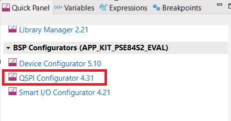
By default the PSOC™ Edge code example will execute from QSPI flash. To execute the application from OSPI flash, after provisioning the device to boot from the external OSPI flash, program your application to the OSPI flash. If you are using the Eclipse IDE for ModusToolbox™ and basic secure app, open the QSPI configurator from the
Quick Panel
.
Figure 14.
Open QSPI Configurator from the Quick Panel
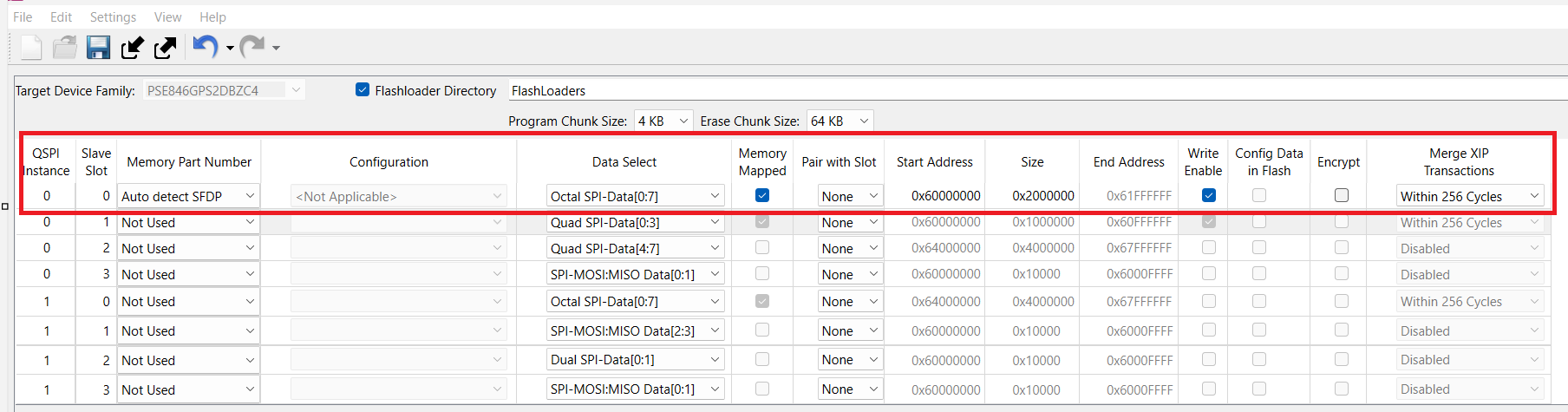
Configure the OSPI flash in the configurator as shown in the figure below. Save the changes, and close the configurator window. Build and program the code example. It now executes from the OSPI flash.
Figure 15.
Configure OSPI flash in the configurator
See "Booting from external OSPI flash" section in the
AN235935 - Getting started with PSOC™ Edge E8 on ModusToolbox™ software
for more details on programming to OSPI flash.
Using RAM load feature of Extended Boot
Extended Boot supports the RAM loading feature that allows the first user application to be programmed to external flash or internal RRAM but executed from the SRAM or system SRAM (SoCMEM). This feature supports the first user application to be copied to SRAM or system SRAM (SoCMEM) by the Extended Boot, and then verified and launched from this memory.
To make use of this feature, the first application should be compiled to execute from SRAM or system SRAM (SoCMEM) memory as required. Ensure that the application linker/scatter file is modified appropriately for SRAM/system SRAM (SoCMEM) execution
The
edgeprotecttools
sign-image/image-metadata command can then be used to change the application start address to an internal RRAM or external flash address as required.
$ edgeprotecttools image-metadata --image userapp.hex --output userapp_signed.hex --hex-addr 0x70100000 --load-addr 0x34008000 --erased-val 0xffTable 10.
Command-line parameters for image-metadata
Command option
Example parameter
Description
--image
/
-i
userapp.hex
Input path to the user application
--output
/
-o
userapp_signed.hex
Path where the application image with signature should be saved
--hex-addr
0x70100000
Flash address where the image should be programmed
--load-addr
/
-L
0x34008000
Load address of the image when it should be run from CM33 SRAM/system SRAM (SoCMEM)
--erased-val
/
-R
0xff
The value which is read back from the erased flash. Default: 0
Program the signed application generated in the previous step
Using alternate serial interface capability of the Extended Boot
The default Extended Boot provisioned on the PSOC™ Edge MCU allows the user to provision and program the device via an alternate serial interface (UART, SPI, I2C). This interface also allows CM33 projects called 'CM33 RAM Apps' to be downloaded into the device and executed before the standard user code that is stored in RRAM is executed. The download protocol is the same used for the Infineon device firmware upgrade (DFU) protocol.
See the ModusToolbox™ code example PSOC™ Edge CM33 RAMAPP for a demonstration of programming the CM33 RAM application using an alternate serial interface and booting the same.
For more information on the alternate serial interface capability, see
Alternate serial interface
section.
Note:
There are two types of RAM Apps. The 'SE RAM Apps' that run on the Secure Enclave (SE). Only Infineon signed SE RAM Apps can run on the device. 'CM33 RAM Apps' can be written by the user. If the device's secure boot flag is set, then the CM33 RAM App must be signed by the OEM_ROT_KEY.
Alternate serial interface
PSOC™ Edge MCU is shipped with an Extended Boot version that has a built-in alternate serial interface capability that enables the user to provision and program the device using serial interfaces such as UART, SPI, and I2C instead of the SWD/JTAG interface. The same provisioning software will be used whether the user selects to use the default SWD interface or one of the serial interfaces defined with the alternate serial interface.
This serial interface is intended to perform the following tasks:
Writing to SRAM
Reading from SRAM
Full device provisioning
Loading and initiating launching of CM33 RAM Apps
To provide alternate serial interface functionality, Extended Boot uses the device firmware update (DFU) protocol as a serial communication protocol. The implementation is provided by the DFU middleware library. See the
AN236282 - Device Firmware Update (DFU) middleware (MW) for ModusToolbox™
for more details on the DFU protocol. Extended Boot supports only a subset of the DFU commands, see
Serial interface commands
section for the supported commands.
DFU Host Tool application is used as a host application for programming and Edge Protect Tools for device provisioning.
The alternate serial interface capability of the Extended Boot can be enabled/disabled through the OEM policy "enable_alt_serial". The default policy enables the alternate serial interface. See
Policy file
for more details. The alternate serial interface may be left enabled after the OEM has shipped the product or deactivated once the device is shipped in production.
Note:
The current version of the Extended Boot shipped with the device supports the UART, SPI, and I2C interfaces. An alternate Extended Boot version is also available that can save about 27 KB of RRAM. This version of the Extended Boot will not support the alternate serial interfaces, so the only option for programming and provisioning will be the SWD interface.
Configuring the alternate serial interface
During the boot sequence, Extended Boot tests the GPIO P20.1 if it is pulled hard with a 5K or less resistor to either Vss or Vdd. If it is not, the alternate serial interface is disabled and the boot sequence does not attempt to communicate with an alternate serial interface and continues its normal boot sequence.
If P20.1 is connected to either Vss or Vdd via a 5K or lower resistor, then the alternate serial interface is enabled. It looks at P20.1 and P20.2 to determine which of the alternate serial interfaces is used.
To determine if P20.1/2 has a low impedance (<5K) connection to either Vss or Vdd, it enables each of the internal 50K pull-up and pull-down resistors to see if the signal tracks the internal pull-up/down resistor.
P20.1 = Tristate | P20.1 = Vss | P20.1 = Vdd | |
|---|---|---|---|
P20.2 = Tristate | Serial Disable | SPI | UART |
P20.2 = Vss | Serial Disable | SPI | UART |
P20.2 = Vdd | Serial Disable | I2C | UART |
Note:
Smaller parts may not bond out P20.2. In this case, you will only have the option to use either SPI or UART for the alternate serial interface.
specifies the GPIO pins used for decoding the serial port and the pins used for the interface itself.
Pin function | Number of pins* (min total) | Ports used | Comment |
|---|---|---|---|
Enable | 1 (2 opt) | P20.1 (P20.2 opt) | Serial Disable P20.1 = Tristate Serial Enabled if P20.1 connected to Vdd or Vss with ≤ 5K resistor. Tristate: Resistance from pin to Vss or Vdd > 150K. See table below. P20.1 = ENABLE P20.2 = SELECT |
UART | 2 (4) | TX/ P9.2 RX/ P9.3 | Serial block used is SCB(1) ** Baud = 115K, Bits = 8, Stop Bits = 1, RTS/CTS = No, Parity = None |
I2C | 2 (4) | SDA/ P9.2 SCL/ P9.3 | Serial block used is SCB(1) ** Speed = 400K, Mode = Slave, 7-bit addr., address = 0x35 |
SPI | 4 (6) | MOSI/ P9.2 CLK/ P9.3 SEL0/ P9.0 MISO/ P9.1 | Serial block used is SCB(1) ** Mode = Slave, Motorola 00 (CPHA = 0, CPOL = 0), Speed ≤ 12 Mbps |
Note:
The 5K resistors specified in this table may be 5K (4.7K) or less
When a pin is in tristate, then the resistance between the pin and Vss or Vdd should be less than 150K
Configuring the alternate serial interface on PSOC™ Edge EVK
Configure the J20 and J21 jumpers on the EVK for enabling the serial interface capability of the Extended Boot as shown in
Table 13
. For example, keep J20 jumper in 2-3 position and J21 jumper in 1-2 position for selecting the I2C interface.
Serial connection | J20 position | J21 position |
|---|---|---|
Disabled | NC | X |
SPI | 2-3 | NC/2-3 |
I2C | 2-3 | 1-2 |
UART | 1-2 | 1-2 |
Make the following connections on the board to enable the serial communication.
Interface | Signal (MiniProg4 pins) | EVK pins |
|---|---|---|
UART | RX | SERIAL_INT3 |
TX | SERIAL_INT2 | |
I2C | SCL | SERIAL_INT3 |
SDA | SERIAL_INT2 | |
SPI | MOSI | SERIAL_INT2 |
SCLK | SERIAL_INT3 | |
SS | SERIAL_INT0 | |
MISO | SERIAL_INT1 |
For example, to select the I2C interface, make the following connections:
Connect SERIAL_INT2 pin on EVK to SDA (Pin 2) of MiniProg4
Connect SERIAL_INT3 pin on EVK to SCL (Pin 4) of MiniProg4
Additionally make required VDD (1.8 V) and GND connection
Figure 16.
Serial interface pins connection
Provisioning using alternate serial interface
After making the required hardware configurations for using the alternate serial interface usage, the device can be provisioned using the following
edgeprotecttools
commands.
Configure the tools to use serial interface communication. Edge protect tools uses the DFU Host Tool to communicate with the device over serial interfaces
$ edgeprotecttools set-ocd -n serial -p <path-to-dfuh>/dfuh-tool/dfuh-cli.exeNote:
Provide the absolute path to the DFU Host Tool executable. The DFU Host executable can be found in this path
C:/Users/<username>/ModusToolbox/tools_3.6/dfuh-tool
Select any one of the serial interface type to use
I2C interface
$ edgeprotecttools -t pse8xs2 serial-config --protocol i2c -hwid MiniProg4-1122055A02010400 --i2c-address 53Note:
I2C address 53 (0x35) must be used
SPI interface
$ edgeprotecttools -t pse8xs2 serial-config --protocol spi -hwid MiniProg4-1122055A02010400 --spi-clockspeed 1Note:
SPI clock speed value is in MHz. Supports speed up to 6 MHz with KitProg3/MiniProg4. Maximum speed up to 12 MHz can be achieved
UART interface
$ edgeprotecttools -t pse8xs2 serial-config --protocol uart --hwid COM5
Note:
The 'hwid' can be obtained by checking the GUI of the
dfuh-cli.exe
Figure 17.
DFU-HT GUI
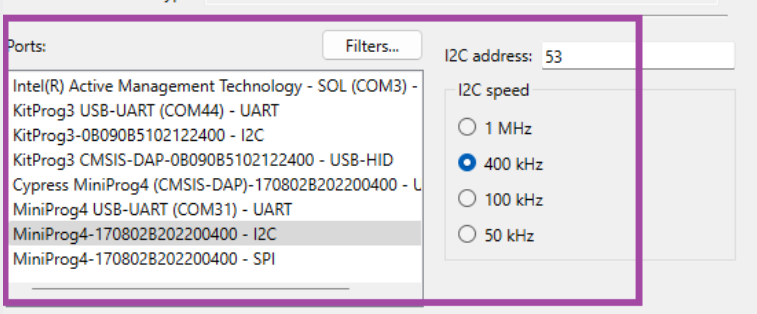
Table 15.
Command-line parameters for serial configuration
Command option
Example parameter
Description
--protocol
uart | i2c | spi
Serial communication protocol to be used
--hwid
MiniProg4-1122055A02010400
Specifies the ID of the hardware. If this option is skipped, the first appropriate device found will be used.
--i2c-address
53
Sets the address for the I2C protocol [Integer range 8<=x<=120]
--spi-clockspeed
1
Sets the clock speed for the SPI protocol in MHz
Reset the kit and check whether the connection is successful by executing the below command
$ edgeprotecttools -t pse8xs2 device-infoProvision the device using the following command
$ edgeprotecttools -t pse8xs2 provision-device -p policy/policy_oem_provisioning.json --key keys/oem_private_key_0.pem --ifx-oem-cert packets/apps/prov_oem/oem_cert.binNote:
See the
Getting started
section for information on how to generate keys and certificate and transfer the ownership. This step is required one time before provisioning
Serial interface commands
The serial communication protocol will use the same format and command structure as the DFU. See the
AN236282 - Device Firmware Update (DFU) middleware (MW) for ModusToolbox™
for full documentation of how DFU functions a protocol.
lists the DFU commands that are supported by the Extended Boot.
Supported commands | Command ID | Description | Remarks |
|---|---|---|---|
Enter DFU | 0x38 | All other commands except Exit DFU are ignored until the command is received | – |
Sync DFU | 0x35 | Resets the DFU to a known state. Any data that was buffered is discarded | – |
Exit DFU | 0x3B | Ends DFU operation | – |
Send Data | 0x37 | Transfers data to the DFU buffer and awaits a Program Data or Verify Data command. If a series of Send Data commands are sent, the data is appended to the buffer | – |
Send Data w/o Response | 0x47 | Same as Send Data except no response is sent back. | – |
Program Data | 0x49 | Writes data to a provided memory location and may follow a series of Send Data or Send Data without Response | The only valid location is a designated location in the SRAM for CM33 RAM Apps. See Policy file |
Verify Data | 0x4A | Validates the code in SRAM beginning at the location designated for CM33 RAM Apps | The CRC is calculated over the area provided and compared to the supplied 32-bit CRC. Note: Both Data and Applications are considered and will be verified in the similar way |
Erase Data | 0x44 | Erases data in memory | This erases only data in the designated SRAM location that may contain a CM33 RAM App |
Run RAM App | 0x50 | Instructs the Extended Boot to execute the CM33 RAM App stored is SRAM | If "secure_boot" is enabled in the policy, the RAM App will be validated with the OEM_ROT_Key. If validation fails, the RAM App will not be executed. If the device is not in the secure boot mode, the verify application command should be used prior to execution to validate the data transfer |
Stage SE RAM App | 0x52 | Sets the required registers to tell the Secure Enclave that a SE RAM APP has been installed and then resets the device | Since the alternate serial interface may be used to directly download a SE RAM APP (Without the need of a CM33 RAM APP), this provides a simple method to install and run the SE RAM APP |
Read Memory | 0x51 | Reads a contiguous block of memory in SRAM | Given an address and length, n bytes will be returned. The data length should be between 1 byte and 256 bytes |
Arm® TrustZone and protection units
Arm® TrustZone technology for Arm®v8-M is an optional security extension that is enabled on the Cortex®-M33 core of the PSOC™ Edge device. TrustZone provides system-wide security by partitioning the resources (memory and peripherals) into secure or non-secure worlds. TrustZone introduces the secure and non-secure states of the processor that are orthogonal to the existing Thread and Handler modes. On the PSOC™ Edge device. With the TrustZone extension always enabled, the Cortex®-M33 CPU always starts in Secure state.
This technology enables the system and the software to be partitioned into secure and non-secure worlds. Secure software can access both secure and non-secure memories and resources, while non-secure software can only access non-secure memories and resources. The isolation between secure and non-secure worlds is memory map based. The partitioning of memory map is achieved with a programmable secure attribution unit (SAU) and a fixed Implementation defined attribution unit (IDAU).
Figure 18.
TrustZone processor modes
Protection unit and controllers are implemented to enforce security based on different operations. A protection unit allows or restricts bus transfers based on the specific properties of a transfer. The hardware that evaluates these protection attributes, to restrict or permit access, is the protection unit. The PSOC™ Edge E84 device has different types of protection units such as security attribution unit (SAU), implementation defined attribution unit (IDAU), memory protection unit (MPU), memory protection controller (MPC), peripheral protection controller (PPC), and master security controller (MSC). Protection units have a distinct set of MMIO registers that helps to define different protection regions and their attributes.
Protection unit/controller | Description |
|---|---|
Memory protection unit (MPU) | MPU is a programmable unit that allows privileged software to define memory access permission. It monitors the transactions including instruction fetches and data access from the processor |
Master security controller (MSC) | MSCs are instantiated to provide security extension attributes to add TrustZone capability. Examples of masters are DMA/DW, NNLite, Crypto, etc. |
Memory protection controller (MPC) | MPCs are intended for implementing protection in a situation with multiple bus masters. MPC implements a concept called Protection Context |
Peripheral protection controller (PPC) | PPCs are protection units provided in the peripheral register space for peripheral protection |
Note:
See the
architecture reference manual
for more information about TrustZone and protection units implementation in PSOC™ Edge.
Cryptographic accelerators
PSOC™ Edge support two types of crypto accelerator blocks:
Two instances of CryptoLite block within the Secure Enclave, one within each island of replication
One instance Crypto block is available outside of the Secure Enclave.
The Secure Enclave provides cryptographic services in a walled-off environment with access restrictions. Along with CryptoLite, there are also software implemented crypto algorithms that are DPA/Fault Injection protected. The crypto services provided by the Secure Enclave are accessible via the PSA Crypto APIs (on EPC 4 devices). PSA APIs enable user applications to discover about the various ciphers that are DPA/Fault Injection protected. Any operations that do not use the DPA/FI protection and accessed through the PSA API will be off-loaded to hardware accelerators such as the CryptoLite hardware.
The Crypto block is outside of the Secure Enclave and is directly accessible by user applications and libraries such as the MBedTLS library. It supports a broad set of cryptographic algorithms for high-performance operations, such as:
Advanced encryption standard (AES) functionality per FIPS 197
(Triple) Data Encryption Standard (TDES/DES)
CHACHA stream cipher functionality per RFC 7539
Secure hash algorithm (SHA) functionality per FIPS 180-4/FIPS 202
Cyclic redundancy checking (CRC)
Pseudo random number generator (PRNG)
True random number generator (TRNG)
Vector unit (VU) to support asymmetric key cryptography, such as RSA and ECC
Note:
Platform security architecture (PSA) and the trusted firmware-M (TF-M)
The platform security architecture (PSA) firmware framework specification defines a standard programming environment and firmware interfaces for implementing and accessing security services within the root of trust for a device.
The PSA security model divides execution within the system into two domains:
Non-secure processing environment (NSPE)
Secure processing environment (SPE)
Non-secure processing environment (NSPE) | Secure processing environment (SPE) |
|---|---|
Application firmware | Security firmware |
OS Kernel and libraries | Security peripherals |
Most I/O peripherals | Root of trust secrets |
The PSA security model requires that no NSPE firmware or hardware can inspect or modify any SPE hardware, code, or data. Security functionality is exposed by PSA as a collection of root of trust (RoT) services. Each RoT service is a set of related security functionality. For example, there might be an RoT Service for cryptography operations, and another for secure storage. PSA further subdivides the SPE into two sub-domains: the PSA root of trust and the application root of trust. The PSA Root of Trust provides the fundamental RoT services to the system, as well as managing the isolated execution environment for the application RoT services.
SE RT services library implements the PSA RoT services in the PSOC™ Edge EPC 4 parts. These parts are compliant up to PSA level 4 certification requirements.
Trusted firmware-M (TF-M) is an open-source software that implements the Arm® platform security architecture (PSA) specifications, which enables PSOC™ Edge to become PSA certified device. TF-M leverages the TrustZone and other security features of PSOC™ Edge to establish an isolated secure processing environment (SPE) where sensitive information can be securely stored and processed.
In the PSE84 device, TF-M relies on the MCUboot-based Edge Protect Bootloader for secure boot and secure firmware update services.
See
AN240096 - Getting started with Trusted Firmware-M (TF-M) on PSOC™ Edge
for instructions on getting started with TF-M on the PSOC™ Edge device.
Secure firmware update
PSOC™ Edge device supports firmware update solution that allows user to upgrade their firmware with newer versions. User can also roll back to the previous versions of the firmware in case of any errors with the newly updated image. The secure firmware update process ensures that only authenticated firmware is updated on the device.
The firmware update process involves writing the upgrade firmware image into the secondary slot on the device and a secured bootloader such as the Edge Protect Bootloader is used to verify the image and copy it to the primary image slot to boot. Edge Protect Bootloader supports 'swap' and 'overwrite' mechanism of firmware update. With the 'swap' update mechanism, the primary and secondary images will be swapped and if the new primary image is not validated, firmware will be rolled back to the previous version on the next reset. Once the new image has been validated, the swap will be marked as permanent. This is useful if there is any issue with the newly updated image. With the "overwrite" mechanism, the primary image is simply overwritten by the secondary image and the firmware cannot be rolled back to the previous version. Edge Protect Bootloader also supports encrypted firmware update and details can be found in the code example
README.md
file.
Firmware update on the device is supported over the wired and wireless interfaces. Wired firmware update can be performed over the SWD/JTAG or serial interfaces. Firmware update over serial interface is supported by the Device Firmware Update (DFU) middleware library and DFU Host Tool. It supports serial interfaces, such as SPI, I2C, UART, and USB. See the
AN236282 - Device Firmware Update (DFU) middleware (MW) for ModusToolbox™
for more information about DFU MW.
Wireless firmware update is supported by the over-the-air (OTA) middleware library over interfaces, such as HTTPS, MQTT, and Bluetooth®. The OTA MW receives the upgrade image over-the-air, writes the image to the secondary slot of the device and triggers a reset. During device bootup, the Edge Protect Bootloader will check the secondary for update image and copy to the primary slot for booting.
Figure 19.
Firmware update overview
Authenticated debug
The Cortex®-M33 and Cortex®-M55 CPUs are associated with a dedicated debug access port called the CM33_DAP and CM55_DAP. These debug access ports give access to the internal debug components of the respective CPUs and the rest of the system through the respective MIMO. Additionally, there is a system wide access port known as the SYS_AP. SYS_AP provides access to other system resources such as the SRAM, RRAM, OTP, and MIMO regions.
PSOC™ Edge provides the following debug features:
Dedicated debug ports for CM33 and CM55 CPUs, along with an additional SYS_AP
Ability to permanently activate/deactivate debugging
Ability to enable debugging after authentication (debug authentication)
Ability to enable debugging through a trusted firmware like TF-M
Support for four debug states for CM33 debug access ports
Non-invasive debug (niden)
invasive debug (dbgen)
secure privileged invasive debug (spiden)
secure privileged non-invasive debug (spniden)
Ability to disable/enable CM33 secure debug
Support for two debug states for CM55 debug access ports
Non-invasive debug (niden)
Invasive debug (dbgen)
Resource protection using MPC when SYS_AP is accessible
PSOC™ Edge devices are shipped in the development life cycle state (LCS), with a default debug policy that ensures that all debug ports are open to allow seamless development and debugging out of the box. Within the development LCS, user can explore the debug policy, enforce debug restrictions, and enable debug ports through the authenticated debug mechanism.
In the development life cycle, the SYS_AP always remains open irrespective of the policy configuration. This avoids devices from getting bricked during development and allows for recovery of the device through the SYS_AP.
In the Production LCS, you can disable/close all debug ports, including the SYS_AP.
Note:
For PSA L4 compliance, in Production LCS OEM shall disable all the debug ports or enable ports with authenticated debug access only before shipping the device out of the factory.
Note:
When both CM33_DAP and SYS_AP are closed, you cannot provision/re-provision the device via SWD interface.
Appendix
Policy file
The policy file controls aspects of the boot procedure that need to be assigned prior to running the first OEM code.
Table 19
describes the most common parameters that may be set by the OEM.
In an application folder that has been initialized with Edge Protect Tools (see
Initialize the application directory
), the JSON policy file can be found in the
<application-directory>/policy/policy_oem_provisioning.json
path.
Parameter | Type/ allowed values | Default value (default if absent) | Description |
|---|---|---|---|
extended_boot_policy | |||
secure_boot | (Boolean) true, false | false (false) | Disable/enable secure boot option |
clock | (Number) 200, 100, 50, 5 | 200 (200) | Defines the default core clock speed in MHz |
listen_window | (Number) 0…255 | 100 (0) | Defines listen window timeout in ms |
enable_alt_serial | (Boolean) true, false | true (false) | Disable/enable alternate serial interface. This field is ignored for the Extended Boot version without DFU. |
cm33_ram_app.enable | (Boolean) true, false | true (false) | Disable/enable CM33 OEM RAM applications. (CM33 RAM APP). This field is ignored for the Extended Boot version without DFU |
cm33_ram_app.address | (Number) 0x340080000 … 0x340FFFFF | 0x34008000 (0x34008000) | Start address of the CM33 OEM RAM application (CM33 RAM APP). This is actually the beginning of the MCUboot header, not the stack and reset vectors This is the start address where the serial interface may write a CM33 RAM APP or data into SRAM. Combined with the cm33_ram_app_size, it defines the area in SRAM where data can be written. This field is ignored for the Extended Boot version without DFU |
oem_app_address | (Number) 0x3200B000 … 0x3206AFFF | 0x32011000 (0x32011000 with alternate serial interface) (0x3200B000 without alternate serial interface) | Starting location of the OEM application. This should point to the header of the first OEM code (most likely the OEM bootloader) If the code header includes the "ram_load" TLV, the code block will be copied to SRAM or SOCMEM. If secure boot is enabled, the code block will be validated prior to being executed. Each version (with an alternate serial interface and without it) of the Extended Boot can have a default location where the first OEM code should start By default, the location pointed to will be at the beginning of the user RRAM |
oem_alt_boot | (Boolean) true, false | true (false) | If this parameter is set to "true", GPIO P17.6 will be examined. If P17.6 is high, the location pointed to by oem_alt_app_address is the location of the first OEM code. If the GPIO P17.6 is low, the location pointed to by "oem_app_address" is the location of the first OEM code. By default, oem_app_address points to a location in RRAM If this parameter is set to "false", the GPIO P17.5 will not be evaluated, and the boot flow will execute as normal |
oem_alt_app_address | (Number) | 0x70100000 | This is the alternate start location that is used if the GPIO P17.6 is pulled high and "oem_alt_boot" is set to true. This can be any address, but it is intended to be in the external flash address range If the code header includes the "ram_load" TLV, the code block will be copied to SRAM or SoCMEM. If secure boot is enabled, the code block will be validated prior to being executed The default address will be at the beginning of the external flash area |
extended_boot_policy.external_flash | |||
smif_chip_select | (Number) 0, 1, 2, 3 | 1 (0) | This selects which chips will be connected to the primary external flash used for XIP |
smif_data_width | (Number) 4, 8 | 4 (4) | This selects the data width used to interface with the external flash used for XIP |
smif_data_select | (Number) 0, 2 | 0 (0) | This determines what data IO pins d0/d1 start at |
Debug.cm33 | |||
cpu | Disabled, Enabled, Allowed | Enable (Enable) | CPU access port debug restriction |
allowed | Firmware, Certificate, Open | Open (Open) | Indicates who is allowed to access the AP. The option is applicable when CPU control is 'Allowed' |
dbgen | (Boolean) true, false | true (true) | Invasive debug. It implies that non-invasive is also enabled |
niden | (Boolean) true, false | true (true) | Non-invasive debug (monitoring without control) |
spiden | (Boolean) true, false | true (true) | Secure privileged invasive debug. The control field is not applicable in the development LCS |
spniden | (Boolean) true, false | true (true) | Secure privileged non-invasive debug. The control field is not applicable in the development LCS |
secure | (Boolean) true, false | true (true) | Secure privileged debug. The control field is not applicable in the development LCS |
Debug.system | |||
ap | Disabled, Enabled, Allowed | Enabled (Enabled) | System access port (SYS-AP) restriction |
allowed | Firmware, Certificate, Open | Open (Open) | Indicates who is allowed to access the AP. The option is applicable when AP control is 'Allowed' |
mpc_ppc_enable | (Boolean) true, false | true (true) | Indicates that the MPC/PPC on the system access port must be programmed and locked according to the settings in the next 4 fields |
rram_otp_enable | Entire Region, Nothing | Entire region (Entire region) | This field indicates if access is allowed for general-purpose OTP |
rram_nvm_enable | Entire region, 7/8th, 3/4th, 1/2, 1/4th, 1/8th, 1/16th, Nothing | Entire region (Entire region) | This field indicates what portion of RRAM MAIN_NVM (including the reclaimed area of PROTECTED_NVM but excluding MAIN_NVM region 0 and region 1 |
ram_enable | Entire region, 7/8th, 3/4th, 1/2, 1/4th, 1/8th, 1/16th, Nothing | Entire region (Entire region) | This field indicates what portion of SRAM is accessible through the system access port. Only a portion of SRAM starting at the bottom of the area is exposed, for example, 'rram_nvm' option |
mmio_enable | All MMIO registers, 7/8th, 3/4th, 1/2, 1/4th, 1/8th, 1/16th, Nothing | All MMIO registers (All MMIO registers) | This field indicates what portion of the MMIO region is accessible through the system access port |
Security features of EPC 2 and EPC 4 category parts
Sl. No. | Security features | EPC 2 | EPC 4 | Comment |
|---|---|---|---|---|
1 | Secure boot | The chain of trust includes up to the first OEM code. The policy file parameter determines if secure boot is extended to the first OEM code | The device always implements secure boot for all internal code supplied by Infineon. OEM may extend the secure boot with custom bootloader | |
2 | Secured debug | Yes | – | |
3 | Support Secure Enclave shut-down mode | Yes | OEM code may choose to shut down Secure Enclave to save power after services are no longer needed. Note: This function is not supported in pre-production parts | |
4 | OEM policies | Yes, and authenticated by an OEM RoT key | – | |
5 | Transition to production LCS | Yes | – | |
6 | Transition to RMA LCS | Yes, with authentication | – | |
7 | OpenRMA with debug token | Yes, and signed by Infineon | – | |
8 | Integrity check of Extended Boot by M0SECCPUSS | Yes | – | |
9 | IFX_DEVICE_CERT | Yes | – | |
10 | Upgrade of Extended Boot during development LCS | Yes | Not upgradeable once the device is in production LCS | |
11 | OEM RoT Keys (Pub keys) | Yes, it supports initial and alternate keys in case key revocation is required. | – | |
12 | Secured run-time services (SE_RT_SERVICES) | No | Yes | – |
13 | Secured upgrade of RT Services | NA | Yes | – |
14 | Basic run-time services (includes cryptographic operation) | Yes | – | |
15 | DICE DeviceID Keypair | Yes | Yes | Private portion of the DICE DeviceID Keypair is not accessible outside of the Secure Enclave. It can be accessed only by the SE RT services available in the EPC 4 device |
16 | ALIAS Keypair | Yes | Yes | For EPC 2 devices, the alias key pair within the Secure Enclave is not accessible. A copy of the alias key pair is stored in the MAIN NVM region, referred as IAK_LITE keys. |
17 | True random number generator (TRNG) support in MXCRYPTO | Yes | Yes, both the CM33 domain and TRNG are used in Secure Enclave | CM33 always has access to MXCRYPTO |
18 | OEM_KEYS (OEM custom keys; OEM cannot be used if RT services are not available) | No (Only OEM_ROT_KEY) | Yes | – |
Application notes
Following application notes are available for security and bootloader-related topics.
Application note number | Application note title | Description |
|---|---|---|
AN240096 | Getting started with Trusted Firmware-M (TF-M) on PSOC™ Edge | Provides guidance on getting started with using TF-M with PSOC™ Edge |
AN238041 | PSOC™ Edge Provisioning specification | Provides information on the assets required for provisioning the PSOC™ Edge device |
AN236282 | Device Firmware Update (DFU) middleware (MW) for ModusToolbox™ | Provides information on DFU middleware for PSOC™ Edge |
Code examples
Following ModusToolbox™ code examples are available for security and bootloader topics.
Code example name | Description |
|---|---|
PSOC™ Edge Basic Secure App | Code example to get started with security topics. Demonstrates secure boot with Extended Boot and Edge Protect Bootloader. |
PSOC™ Edge Protect Bootloader | Code example demonstrating MCUboot capabilities |
PSOC™ Edge CM33 RAMAPP | Demonstrates booting CM33 application from RAM |
PSOC™ Edge SRAM Loading | Demonstrates the SRAM loading capability of Edge Protect Bootloader |
PSOC™ Edge Crypto AES | This code example encrypts and decrypts user input data using the AES algorithm with a 128-bit key. The encrypted and decrypted data is displayed on the UART terminal emulator. |
PSOC™ Edge Crypto SHA | Demonstrates how to generate a 32-byte hash value or message digest for an arbitrary user input message with the SHA-256 algorithm using the cryptographic hardware block in PSOC™ Edge MCU. |
PSOC™Edge MBEDTLS PSA Crypto | This code example shows how to use PSA APIs from MbedTLS library for cryptographic operations on PSOC™ Edge MCU. |
PSOC™ Edge Basic Trusted Firmware-M (TF-M) based application | The example demonstrates how to initialize the TF-M NS interface in CM33 NS project and use the services offered by TF-M with PSA APIs |
PSOC™Edge TF-M Crypto Application | This code example demonstrates cryptography using Trusted Firmware-M (TF-M) on PSOC™ Edge MCU |
PSOC™ Edge TF-M based Initial Attestation | Demonstrates how to use the Initial Attestation service offered by TF-M to generate a attestation token |
PSOC™ Edge OTW Update | Demonstrates how Infineon's Device Firmware Update Middleware (DFU) can be utilized to update firmware over a serial interface. |
PSOC™ Edge DFU User-defined commands | This code example demonstrates how Infineon's Device Firmware Update Middleware (DFU) can be utilized to send DFU user-defined commands over a serial interface. |
Glossary
If you are new to embedded device security and/or new to Infineon's line of PSOC™ Edge MCU devices, some of the terminology may be new to you. The following is a list of terms that will be used throughout the document:
Concise binary object representation (CBOR): This format is used to store the owner's policy in the device's NVM
Debug access port (DAP): There may be multiple DAPs in this device accessible to the customer; System, CM33, and CM55
Development LCS: This is the stage that the device is in during development. In this stage, no permanent changes are made to the device, and it may be reverted back to its original state that was shipped from Infineon. The user may transfer ownership as many times as needed while in this stage
Device firmware upgrade (DFU): DFU is the act of transferring data from the host to the target flash either using a wired interface or a wireless interface and booting to newly downloaded firmware
Extended Boot: This is the first code executed by the CM33 during the secure boot process. It interprets the OEM_POLICY file and boots the first OEM code based on the policies in this file
Evaluation kit (EVK): Fully assembled board with working circuit used for evaluation and development
First OEM code: This is the first CM33 OEM code that is executed after the device is booted. This is often a bootloader, such as MCUboot. It can also be a test software used to evaluate the device
Data tightly coupled memory (DTCM): A high-speed SRAM location in the CM55 where data may be stored for optimal performance. This is not the same as a data cache
Hash: A crypto algorithm that generates a repeatable but unique signature for a given block of data. This function is not reversible
IPC: Inter-processor communication. Hardware used to facilitate communication between two or more CPUs
Instruction tightly coupled memory (ITCM): A high-speed SRAM location in the CM55 where instructions may be stored for optimal performance. The startup firmware must copy the code into this memory space prior to execution. This is not the same as an instruction cache
Life cycle stage (LCS): The device is shipped from Infineon in the Development LCS and then will be advanced to the Production LCS when the customer ships the product
MCUboot: An open-source secured bootloader library for 32-bit MCUs aiming to define a common infrastructure for the bootloader and system flash layout on microcontroller systems and to provide a secured bootloader that enables easy software upgrade
Memory protection unit (MPU): Hardware blocks used to allow or disallow access to sections of memory or peripherals to bus masters
Non-volatile memory (NVM): A type of memory that can retain stored information even after power is removed
OEM: Original Equipment Manufacturer, Infineon's customers
OEM_Policy: This file contains the boot-up parameters used
OEM_ROT_KEY: This refers to the OEM_ROT_PUBLIC_KEY and OEM_ROT_PRIVATE_KEY pairs
OEM_ROT_PRIVATE_KEY: This key is used to sign the first OEM code in the system when secure boot is enabled. This key may also be used to sign other projects or firmware updates that are installed on the device
OEM_ROT_PUBLIC_KEY: This is the key used to validate the first OEM code when secure boot is enabled
Production LCS: Once a device is transitioned to this stage, it cannot revert back to the Development LCS. Also, ownership of the device cannot be transferred
Provision: This is the process by which the OEM loads their custom software, keys, and boot parameters into the device. A textual, JSON formatted file (OEM_POLICY) is used to define a set of security-related parameters
Primary code space: This is the location in memory where the code to be executed is stored in non-volatile memory
RAM APP: Executable code that is loaded into SRAM. There are two types of RAM APPs. The SE RAM APPs, which can only be written and signed by Infineon and only run on the M0s in the Secure Enclave. SE RAM APPs are used for provisioning and to update device resources such as Extended Boot and the SE runtime services. The second type of RAM APP is the CM33 RAM APP that can be written and loaded by the OEM and is executed by the CM33
Return merchandise authorization (RMA): This LCS is used if a device is suspected to be defective. The OEM places the device in this stage prior to shipment back to Infineon
Root of trust (RoT): In the PSOC™ Edge MCU devices, the SE ROM code is the root of trust
Resistive random-access memory (RRAM): A type of non-volatile random access memory available on the PSOC™ Edge MCU devices
Secondary code space: This is the area where code updates are stored until they have been copied into the primary
Secure boot: In the context of this document, this refers to when the first OEM code must be signed and then authenticated by the internal Extended Boot code
Secure Enclave (SE): The Secure Enclave contains two CM0+ CPUs that run in lockstep. It controls the debug ports as defined in the OEM_Policy and runs the secured runtime services
Secured runtime services: This is a set-up runtime crypto function that is executed on the SE. It includes key management, memory hashing, code authentication, and so on. The EPC2 parts support only a basic subset of functions that are required for secure boot code authentication. The EPC4 parts provide a wider range of functions, plus key management features
Serial wire debug (SWD): A method used to interface debug and programming tools to the device
SFDP: Serial Flash Discoverable Parameter
TLV: Tag-Length-Value is a way of storing data in a project header that is easily parsed by code
Transfer of ownership: This occurs when the default OEM_CERT from Infineon is replaced with an OEM_CERT from the actual OEM (sometimes referred to as extending ownership)
References
002-37464: PSOC™ Edge E84 MCU architecture preliminary reference manual
002-37465: PSOC™ Edge E84 MCU registers preliminary reference manual
AN235935 – Getting started with PSOC™ Edge E8 MCU on ModusToolbox™ software
AN236282 – Device Firmware Update (DFU) middleware (MW) for ModusToolbox™
AN239774 – Selecting and configuring memories for power and performance in PSOC™ Edge MCU
AN238041 – PSOC™ Edge Provisioning specification
AN240096 – Getting started with Trusted Firmware-M (TF-M) on PSOC™ Edge
Revision history
Document revision | Date | Description of changes |
|---|---|---|
*E | 2025-09-04 | Release to web |
Trademarks
The Bluetooth® word mark and logos are registered trademarks owned by Bluetooth SIG, Inc., and any use of such marks by Infineon is under license.
PSOC™, formerly known as PSoC™, is a trademark of Infineon Technologies. Any references to PSoC™ in this document or others shall be deemed to refer to PSOC™.