AN240916 DEEPCRAFT™ Audio Enhancement on PSOC™ Edge E84 MCU
About this document
Scope and purpose
This application note contains details of DEEPCRAFT™ Audio Enhancement (AE) that is supported by the PSOC™ Edge MCU family. DEEPCRAFT™ Audio Enhancement (AE) includes Audio Front End (AFE) middleware that interfaces to the audio-voice-core algorithms, AFE Configurator, Audio Enhancement application, quick start guide, and this application note.
This application note helps you to understand about Audio Enhancement, various components of AFE middleware and the usage of AFE Configurator. Additionally, it explains how to integrate Audio Enhancement to the embedded code and elaborates on code flow, configuration, and audio tuning for KPI.
See the PSOC™ Edge MCU: DEEPCRAFT™ Audio Enhancement application code example
1
to understand Audio Enhancement.
Intended audience
This document is intended for anyone who are developing audio and voice solutions on PSOC™ Edge MCU using DEEPCRAFT™ Audio Enhancement.
Introduction
DEEPCRAFT™ Audio Enhancement (AE) enables you to customize the audio processing pipeline running on PSOC™ Edge MCU so that the processed audio can be used for Machine Learning (ML) inference and other audio related use cases.
The AE package consists of the following:
Audio Front End (AFE) Configurator:
This runs on the PC and enables you to configure the various audio processing blocks within AFE middleware and also configures the audio pipeline. It generates a
.c
/
.h
file, which should be flashed to the PSOC™ Edge MCU. Install the DEEPCRAFT™ Audio Enhancement Tech Pack to access AFE Configurator via Infineon Developer Center Launcher
2
Audio Front End (AFE) middleware:
This is the middleware component that executes on the PSOC™ Edge MCU. It has a wrapper API and control logic that interfaces between application code and core algorithms
Audio voice core library (audio-voice-core):
This contains the core audio algorithms and is executed on PSOC™ Edge MCU. This is a licensed deliverable from Infineon and supports Arm® and LLVM compilers. The licensed version is available via the DEEPCRAFT™ Audio pack
Audio Enhancement (AE) code example:
This PSOC™ Edge MCU: DEEPCRAFT™ Audio Enhancement application code example
1
is used to demonstrate Audio Enhancement capabilities. You can customize this code example
1
according to your requirement. The
README.md
and
ae_design_guide.md
files included in this code example
1
contains details of design, configuration, KPI, and other details. There is PSOC™ Edge MCU: Mains powered local voice code example 2 that shows how to use the complete audio pipeline with various options and inference engines
Audio Front End (AFE) Configurator user guide:
Explains how to use the AFE Configurator (bundled with the AE Tech Pack)
Audio Enhancement (AE) quick start guide:
Quick start guide on how to setup the AE code example
1
Audio Enhancement (AE) on PSOC™ Edge E84 MCU:
This application note
This application note explains the use of AFE Configurator, AFE middleware, theory of core algorithms, AE application code example
1
, integration and tuning of AFE middleware, along with KPI, and benchmarking details.
The sections are organized as the following:
Audio Front End (AFE) middleware and Configurator : Explains about AFE Configurator, AFE middleware components, and algorithm concepts
Audio Enhancement (AE) operation : Explains the AE application
Audio Enhancement (AE) tuning: Explains how to tune the AFE middleware and its components via the AE application. You can also use local voice-based code examples for tuning and extend it to their use cases
Audio Enhancement (AE) benchmarking : Details the steps for benchmarking AFE components/algorithms and provides the speech quality scores
Integration of Audio Enhancement (AE) to sample audio pipeline: Explains how to integrate AE to code example 1 with code snippets. This can be extended to any audio based code example that requires AE
Audio Front End (AFE) middleware and Configurator
AFE Configurator
AFE Configurator overview
The Audio Front End (AFE) Configurator is a versatile and user-friendly software solution designed to streamline the process of creating and managing the configuration files required by the AFE middleware. With its intuitive interface and straightforward architecture, the AFE Configurator simplifies the task of generating the necessary deployment files from the AFE configuration chosen in the AFE Configurator. AFE configurations include audio input and components of the AFE, such as the High Pass Filter (HPF), Acoustic Echo Cancellation (AEC), Beam Forming (BF), Dereverberation, Echo Suppression (ES), and Noise Suppression (NS).
With USB enabled on the device, the AFE Configurator allows you to send and receive data between the device and the PC over USB. The streamed audio is used for PC- or device-based analysis of audio data for profiling and benchmarking. With this tool, configure the audio settings to enhance audio for different environments, such as noisy or quiet places. The configurator also provides real-time feedback on the audio to help users make informed decisions while calibrating the device.
Figure 1.
AFE Configurator - Tuner view
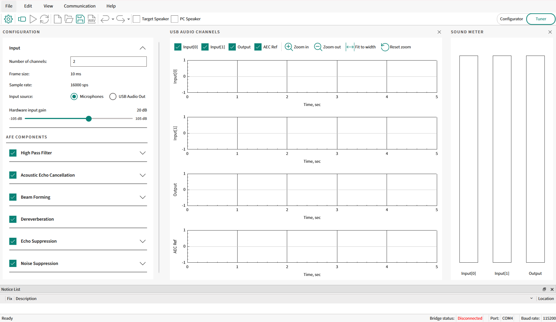
The AFE Configurator shows the components on the left side of the AFE Configurator. Select the required components in the AFE middleware pipeline. Based on the component selection, the configurable parameters of a component are shown under each component in the Tuner view as shown in
Figure 1
. Along with configuring parameters, the audio pipeline tool offers a visualization feature to visualize audio data received from the device.
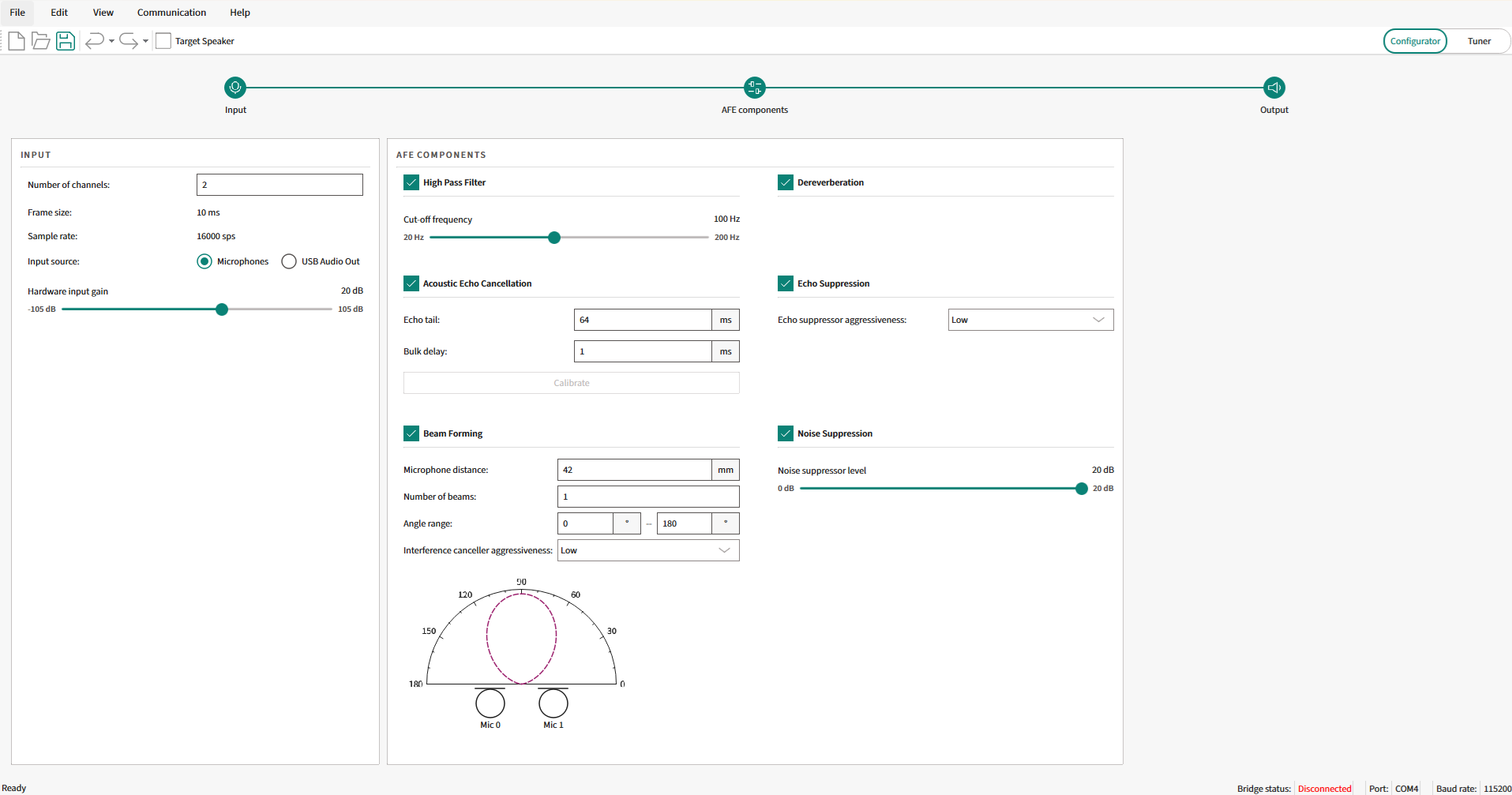
In the AFE Configurator view, all the configurable components are available on the AFE Configurator window.
Figure 2.
AFE Configurator - Configurator view
For details on all GUI components of the AFE Configurator and their usage, see the ModusToolbox™ Audio Front End Configurator user guide that is available as part of DEEPCRAFT™ Audio Enhancement Tech Pack. Once this tech pack is installed, the configurator and user guide will be available at
C:\Users[User-Name]\Infineon\Tools\DEEPCRAFT-Audio-Enhancement-Tech-Pack\tools\audio-fe-configurator\docs
.
AFE Configurator architecture and parameterization
The AFE Configurator is an executable tool that is available in the ModusToolbox™ as a Library Configurator. It can save and load MTBAFE (
.mtbafe
) files and generate source code that will be used by AFE middleware in PSOC™ Edge MCU. The generated source has filter and algorithm settings that will be deployed as a C-flat array for the AFE middleware.
The filter settings generator is an executable used to parse the relevant content from the
MTBAFE
file and generate a binary file that contains the filter settings. This executable is included within the AFE Configurator. The binary file generated by the filter settings generator is parsed by the AFE Configurator and converted into a C-flat array for the AFE middleware. The generated files are called deployment files (
cy_afe_configurator_settings.h
and
cy_afe_configurator_settings.c
) are used by the AFE middleware.
The files consist of C code that has #defines and C-flat arrays. One of the arrays is directly parsed from the filter settings binary file and converted to C code. The other array has an AFE configuration as a C-flat array.
Figure 3
shows the AFE Configurator dataflow between AFE Configurator, filter settings generator, and firmware project through files
.mtbafe
,
.bin
, and deployment files (
cy_afe_configurator_settings.h
and
cy_afe_configurator_settings.c
).
Note:
The
.bin
file is not used in the firmware for deployment.
Overall, the AFE Configurator simplifies the task of generating the necessary deployment files for the chosen AFE configuration. The AFE Configurator generates a configuration C data array and filter coefficients data array based on the input to the configurator tool.
Figure 3.
AFE Configurator dataflow
The configuration and coefficients C data arrays generated by the configurator tool contain all the information about the AFE component pipeline configured. These configuration and coefficient C data arrays are included in the input C header files for the AFE middleware. At the start of middleware initialization, the configuration and filter coefficients data arrays are parsed (that is, processed), and a data container will be initialized. See the
Integration of Audio Enhancement (AE) to sample audio pipeline
section for code snippets.
The configuration C data array is a 32-bit integer data array. The data array contains the following information and follows the order as shown:
Audio Front End Configurator version number
Sampling rate
Audio frame size in number of audio samples
Number of microphones
Number of monitor components (this is used for general tuning or debug purposes; the maximum number of monitor components is four)
List of the identification numbers of the components whose output will be monitored. If there is no monitor component, skip this field and go to the next item
CRC polynomial
Number of AFE components included in the audio pipeline
List of configured component identification numbers
Number of configurable parameters in the 1 st AFE component from the above list of configured components. If the component has no configurable parameter, it is skipped. Otherwise, parameter or parameters are listed. (the order of parameters is based on its data structure defined in the ifx_sp_enh.h public header file). This is continued for the rest of the components enabled in the configurator
Number of configurable parameters in the 2 nd AFE component from the list of components, followed by its checksum based on the CRC polynomial
There are default filter coefficients built into the audio-voice-core library. If you customizes some component’s parameter (for example, high-pass filter cut-off frequency), a new set of filter coefficients will be generated by AFE Configurator. Depending on, if the component can be dynamically updated or statically updated, the AFE middleware will update the required coefficients.
The
ifx_sp_enh.h
public header file contains the data structure defined for each component, which has configurable parameters. The configurable parameters of a component include both compile-time and run-time parameters and follow the order of the list items in its defined data structure. The deployment file generated by the AFE Configurator contains the correct number of configurable parameters and a valid parameter value range, which ensures the correct functionality of the configured AFE component. At the end of the configuration file, there is a 32-bit CRC checksum value so that the integrity of the data can be verified.
There are two types of configurations that are supported:
Static configuration:
Configured at the start and generated deployment files are used during code example build. All the configurable parameters are allowed to be configured through this option. But the optimal value of a few parameters is available only after calibration, so a second configuration, that is, dynamic configuration is used
Dynamic configuration:
A few parameters can be changed in run-time while calibrating or debugging a code example that uses AE. The changed value is communicated from the AFE Configurator to the Target via UART
See the
Audio Enhancement (AE) tuning
section for step-by-step details.
AFE Configurator and target interaction
There are code examples with PSOC™ Edge that use Audio Enhancement to enhance audio data. For example, PSOC™ Edge MCU: Audio Enhancement application
1
and PSOC™ Edge MCU: Mains powered local voice
2
code examples. The generated deployment files from AFE Configurator are compiled with the code example to use Audio Enhancement. See the
Audio Enhancement (AE) tuning
section for step-by-step details on target interaction.
For analysis, access the AFE components parameter and audio data from AFE Configurator.
UART is used for sending dynamic configurations of the AFE component’s parameter from the AFE Configurator and get the target information back to the configurator.
The USB Audio Class (UAC) is used to communicate audio data to and from the target device. The AFE Configurator has options to stream audio data to the device as well as receive data.
Note:
Not all changes in the configuration can be sent over the UART. Some of the configuration items can only be changed at compile-time, that is, generate the Audio Front End profile settings, integrate them into the application, and rebuild it. Some filters can be enabled at compilation time but can be disabled and re-enabled in run-time. If they are disabled at compile-time, they cannot be enabled at run-time.
AFE components
Acoustic Echo Cancellation (AEC) and Echo Suppression (ES)
Echo is a phenomenon in which a delayed and distorted version of an original sound or electrical signal is reflected back to the source. Acoustic echo is caused by the reflections of the sounds (played over a loudspeaker) from nearby surfaces that eventually get captured by the microphone. The echo cancellation methods are used to improve the audio quality by removing the echo present in the signal during transmission. The Acoustic Echo Cancellation (AEC) implemented in the audio-voice-core is distributed echo cancellation, that is, there is a separate AEC instance operating for each microphone. In the case of stereo use cases, there will be two AEC instances operating separately on each microphone, as shown in
Figure 4
.
Figure 4.
AFE component pipeline
AEC theory
AEC is traditionally used in teleconferencing. As shown in
Figure 5
, each side of the communication in the process is named as an "End". The remote end from the speaker is called the far end (FE), and the near end (NE) refers to the end being measured. The speech of the far-end speaker is sent to the loudspeaker at the near end, and it is reflected from the floor, walls, and other neighboring objects, and then picked up by the near-end microphone and transmitted back to the far-end speaker, yielding an echo. The acoustic coupling between the microphone and speaker at the near end produces an echo at the far end.
Figure 5.
Teleconferencing example
The characteristics of the reflected acoustic signal/echo are as follows:
Relatively long echo span (also known as "echo tail"), often exceeding 160 ms
Wide range of echo signal levels, often extending over high signal levels (therefore, corresponding to low Echo Return Loss (ERL) values, reaching negative values in some cases)
Frequent changes in echoes are caused by variations in echo path impulse responses. Echo path impulse responses are the Room Impulse Response (RIR) for a given microphone and loudspeaker positions. If the position of one of the components is changed, the RIR will also change. This mainly happens because of the position of the speaker with respect to reflecting objects in the near-end room
Because of the non-linear behavior of the loudspeaker, the relationship between the acoustic pressure produced by the loudspeaker and the electrical signal driving it is non-linear
In audio and voice code examples of the PSOC™ Edge E84 MCU, the microphone and loudspeaker coupling degrade the voice performance when active playback is happening on the loudspeaker. The AEC is used to remove the "AEC reference" audio from the audio recorded by the microphone. In audio and voice code examples, AEC is needed only when playback is happening over a loudspeaker. At a minimum, the cancellation of acoustic echo requires an AEC reference signal, a microphone signal, and an adaptive filter. The above-mentioned characteristics of echoes require acoustic echo cancellers to be equipped with more advanced adaptive filters and non-linear processors/echo suppressors. For example, the adaptive filters used in acoustic echo cancellers have to cover a well-anticipated echo span, so the adaptive filter length, in milliseconds, has to be at least as long as the echo span.
The AEC has two components to remove the echo completely. Echo cancellation comprises an adaptive filter, which is a linear filter, and an echo suppressor, which will look after nonlinear components in the echo.
Echo Cancellation
A simplified representation of the echo cancellation process is shown in
Figure 6
. The echo canceller removes AEC reference audio sampled by the microphone. At the fundamental level, the echo canceller subtracts the AEC reference from the microphone data. The idea is to get echo-free talker audio to process further in the audio pipeline. In the ideal case, the echo cancellation output is echo-free talker audio. But in real-world scenarios, the AEC reference does not match the echo. There is a difference between AEC reference and echo because echo is altered slightly when played audio interacts with the room surface and each other. Echo will have a different profile if the talker is moving in the room. As echo is not an exact replica of the AEC reference, there is an echo residual even after echo cancellation is employed. To resolve this issue, AEC uses an adaptive filter module. The residual echo will be one of the inputs to the filter module. The adaptive filter module adaptively adjusts the filter coefficient to reduce the residual echo. This is an on-going process called "convergence". The left-over residual echo is removed by the echo suppression component.
Once AEC converges, residual echo is minimal. This is the case when the microphone and speaker are stationary and the room characteristics are not changing in the course of action. As soon as there is a change in the already AEC-converged setup, AEC retriggers, and the process of convergence starts.
shows the AEC component, which removes echo from mic audio data. The AEC component consists of an adaptive filter, an echo canceller, and an echo suppressor.
The AEC reference is fed into the adaptive filter, which continuously receives feedback from the echo canceller. The adaptive filter adjusts the filter coefficients to reduce the residual echo. The updated filter coefficients try to correctly simulate the room impulse response and provide the AEC reference convolved with the room impulse response to the echo canceller. The echo canceller will try to cancel echo from microphone data, but there is a left-over echo in the echo canceller output. The left-over echo is processed by the echo suppressor before being consumed by the AFE components or user application.
Figure 6.
AEC block diagram
The adaptive filters form the core of the AEC. Primarily, there are three steps for an AEC algorithm:
Estimate the characteristics of the echo path h(n)
Create a replica of the echo path signal y(n)
Echo is then subtracted from the captured microphone signal d(n) to obtain a clean signal. clean signal = d(n) - y(n)
Figure 7.
AEC mathematical model
The notations used in
Figure 7
are listed in the following table.
Terminology | Description | Representation |
|---|---|---|
AEC reference | Playback data played over the speaker | x(n) |
Room impulse response | The room impulse response is the transfer function between the sound source and microphone. To recover the original sound source, the received microphone signal can be convolved with the inverse of the room impulse response function | h(n) |
Echo | Acoustic echo traveled from the loudspeaker system to the microphone, either directly or through reflections | y(n) |
User speech | Words uttered by the user, either WW or ASR | s(n) |
Background noise | Background noise captured by the microphone along with user speech | b(n) |
User speech with background noise | User speech plus background noise | v(n) |
Microphone data | Audio data is sampled by the microphone, which includes user speech, playback, and background noise | d(n) |
Adaptive filter response/estimated RIR | RIR is estimated by the adaptive filter | ĥ(n) |
Echo estimation | Estimate of the echo. Ideally, it should match the echo | y^(n) |
Error or EC residual | Residual echo after the echo cancellation stage | e(n) |
The echo path h(n) of the room is normally variable; it depends on the room structure and the moving object inside. The estimated echo yˆ(n) is calculated from the reference input signal x(n) and the adaptive filter ĥ(n). The user speech with background noise v(n) and audio played over a loudspeaker is recorded by a microphone. The microphone audio signal (desired signal d(n)) is
d(n) = v(n) + y(n)
The signals x(n) and y(n) are correlated to get the error signal as:
e(n) = d(n) − yˆ(n) = v(n) + y(n) −
yˆ(n)
The adaptive filter works to minimize the echo (y(n) − yˆ(n)) to be zero to obtain only user speech v(n) in the perfect case.
There are multiple AEC algorithms to realize adaptive filters that can be used for AEC. These algorithms are classified as time-domain and frequency-domain algorithms. The AEC algorithm provided as part of the AFE middleware is a multidelay block frequency domain adaptive filter (MDF). The MDF is a block-based frequency domain implementation of the normalized least mean square filter (NLMS) algorithm. The MDF algorithm is based on the fact that convolutions are efficiently computed in the frequency domain because of the Fast Fourier Transform (FFT). The advantages of MDF over the other algorithms are:
Lower algorithmic complexity is because of the efficiency of block processing in connection with Discrete Fourier Transform (DFT)
Partial de-correlation of the input leads to faster convergence
NLMS uses stochastic gradient-based algorithms at the core, in which the step size parameter is normalized.
Echo Suppression
Echo Suppression is also called as "Non-Linear Processor (NLP)". Echo suppression is one of the two main components of the process for removing unwanted echoes from audio signals. While echo cancellation focuses on modeling and subtracting the echo signal, echo suppression is designed to selectively attenuate the residual echo that remains after cancellation. Echo suppression algorithms work by analyzing the audio signal and identifying the portions of the signal that are likely to contain echo. These portions are then attenuated or suppressed in such a way as to reduce the overall level of the residual echo.
Echo suppression is particularly important in situations where it is not possible to achieve complete echo cancellation, such as in environments with high levels of ambient noise or multiple sound sources. By selectively attenuating the residual echo, echo suppression can effectively improve the overall audio quality of the signal and enhance the intelligibility of speech. However, it is important to note that echo suppression can also have some negative side effects, such as reducing the level of the desired signal or introducing artifacts or distortions into the audio. Therefore, it is essential to carefully balance the trade-offs between echo suppression and other aspects of the Acoustic Echo Cancellation (AEC) system to achieve the best possible results.
The echo suppressor available as part of AE is a Machine Learning-based model that executes out of Arm® Ethos-U55 and is known as "Deep Subband Echo suppression".
AEC parameters
The AEC parameters are categorized into configurable parameters and performance parameters/metrics. The following are the parameters:
AEC configurable parameter
The AEC algorithms use various parameters to adaptively estimate the impulse response of the acoustic channel or environment and then subtract the echo from the microphone signal. Some of the important parameters used in AEC algorithms are echo return loss (ERL), Echo Return Loss Enhancement (ERLE), bulk delay, tail length, and so on. Out of these parameters, some are configurable, and some are used to measure AEC performance. The configurable parameters are:
Bulk delay
There is a measurable delay between the audio data played over a loudspeaker and what is available for audio processing after it is captured by the microphone. The delay contains an acoustic propagation delay and a bulk delay. The acoustic propagation delay is the time taken by the sound waves to travel from the loudspeaker to the microphone. The bulk delay is any extra delay introduced during playback and recording of a signal due to digital audio I/O buffering. To calculate the delay, a reference (chirp) signal is played out and processed with its recording to estimate the Room Impulse Response (RIR) that contains delay information. The Bulk Delay Measurement (BDM) and configuration are done in the calibration phase. To calculate the total delay during calibration, the Bulk Delay Measurement (BDM) algorithm is used. The delay (bulk delay plus acoustic propagation delay) is estimated by the peak location in the RIR plot. The AEC needs to know the non-varying bulk delay that will occur during run time so that it can adjust for the delay appropriately. The typical range of delay in Acoustic Echo Cancellation (AEC) depends on the characteristics of the environment in which AEC operates. Generally, the delay in AEC can range from a few milliseconds to several tens of milliseconds.
Figure 8
shows the BDM block and buffers used in the audio path.
The AFE Configurator provides an option to perform bulk delay measurement.
Figure 8.
Delay measurement
Figure 9.
Room Impulse Response (RIR)

Tail length
Tail length refers to the duration of time that the AEC algorithm continues to adapt after the echo path has changed or the speech has stopped. The tail length is usually set to be long enough to ensure that all echoes have decayed to a negligible level. A longer tail length can result in more accurate cancellation, but it also increases the processing time and can lead to undesirable artifacts in the speech. Conversely, a shorter tail length can reduce processing time but cannot cancel all the echoes. The optimal tail length depends on the specific application and the characteristics of the echo path. Tail length is configured in milliseconds in the range of 0 to 64 milliseconds. Tail length is a compile-time configurable parameter, so it cannot be changed in run time.
Echo suppression aggressiveness
The aggressiveness of echo suppression in Acoustic Echo Cancellation refers to the degree to which the residual echo is attenuated or suppressed. The aggressiveness can be adjusted for the echo suppression algorithm to balance the level of suppression with the preservation of the desired signal and the avoidance of signal distortion or degradation. Low-level aggressiveness provides minimal attenuation of the residual echo, allowing more of the original signal to be preserved. This approach is typically used in situations where the residual echo is low or the echo cancellation system is highly effective. Medium-level aggressiveness provides a moderate level of attenuation of the residual echo. This approach can be effective in suppressing echo in most situations without significantly degrading the quality of the desired signal. High-level aggressiveness provides strong attenuation of the residual echo, which can effectively improve the overall audio quality of the signal. However, this approach can also result in a higher level of signal distortion or degradation, particularly in situations where the desired signal is weak or the residual echo is high.
The choice of aggressiveness level depends on the specific requirements and constraints of the application, such as the level of ambient noise, the characteristics of the audio signal, and the desired level of audio quality. A high-level aggressiveness can be most appropriate in noisy environments or in situations where there is a significant amount of residual echo, while a low- or medium-level aggressiveness can be preferred in situations where the desired signal has a higher priority.
With the ML-based Echo Suppression, a low-level aggressiveness is recommended.
AEC performance parameters/metrics
Echo Return Loss (ERL) and Echo Return Loss Enhancement (ERLE) are two important metrics used to evaluate the performance of Acoustic Echo Cancellation (AEC) systems.
Figure 10
shows the typical acoustic echo cancellation system with a microphone, speaker, and echo canceller. Both ERL and ERLE are shown in
Figure 10
.
Figure 10.
ERL and ERLE measurement
Echo Return Loss (ERL)
The Echo Return Loss (ERL) is a metric used to measure the quality of acoustic echo cancellation. ERL is acoustic echo loss through decay or absorption as the audio signal travels from the loudspeaker system to the microphone, either directly or through reflections. Basically, ERL is room attenuation. ERL is the ratio between the power of the original sound and the sound after it has been received back. ERL is measured in dB as shown in the following formula:
ERL (in dB) = 10 log (P
d
/ P
in
)
P
d
is the power of the AEC reference signal at the microphone-end
P
in
is the power of the AEC reference signal at the speaker end
A high ERL value indicates that the echo has been effectively degraded, whereas a low ERL value suggests that there is still a significant amount of echo present. Typically, an ERL of 20 dB or more is considered acceptable for most applications. The ERL value is affected by the amount of gain at the amplifier, room acoustics, microphone and speaker placement, and ambient room noise.
Echo Return Loss Enhancement (ERLE)
The ERLE is a metric used to measure the improvement in the Echo Return Loss (ERL) achieved by an AEC. The ERLE represents the difference between the ERL before and after the echo cancellation algorithm is applied. The ERLE is measured in dB as shown in the following formula:
ERLE (in dB) = 10 log (P
d
/ P
e
)
Pd is the instantaneous power of the microphone signal
P
e
is the instantaneous power of the error/residual signal
A high ERLE value means that the echo has been effectively removed from the signal, whereas a low ERLE value suggests that there is still a significant amount of echo present. The ERLE is an important metric to consider when evaluating the performance of an acoustic echo cancellation system. It provides a measure of the effectiveness of the echo reduction algorithm in suppressing unwanted echoes and improving the overall audio quality. A high ERLE value indicates that the system is performing well, whereas a low ERLE value suggests that further improvements may be necessary. The ERLE is only appropriate when measured in a quiet room with no background noise.
AEC tuning
Acoustic Echo Cancellation (AEC) tuning is the process of adjusting the parameters of an AEC system to optimize its performance for a specific audio environment. AEC tuning typically involves adjusting the AEC parameters to minimize the residual echo and maximize the audio quality. The tuning process can be challenging, as it requires a detailed understanding of the acoustic properties of the environment and the behavior of the AEC system. It can involve a combination of manual adjustments and automated tuning algorithms, such as adaptive filtering.
ERL and ERLE are used to measure the AEC performance and are used as feedback to tune configurable parameter. The configurable parameters for AEC are tail length, bulk delay, and echo suppression aggressiveness.
On PSOC™ Edge and Audio Enhancement, AFE Configurator provides an option to calculate the bulk delay.
Perform the following steps:
See the
Audio Enhancement (AE) tuning
section and set up the device
Ensure to select only AEC and ES components in AFE Configurator. Save the configuration and flash the firmware to the device
Connect to the device from AFE Configurator
Select
Calibrate
option under
Acoustic Echo Cancellation
. This will play a chirp signal on the device speaker
Once the bulk delay calculation is done, the AFE Configurator will have the updated bulk delay value displayed
Sync to the device from AFE Configurator
Evaluate the AEC performance via USB data (either through Audacity of AFE Configurator)
If the performance is satisfactory, save the configuration and flash to the device
Beam Forming (BF)
Introduction to Beam Forming
All MEMS microphones have an omnidirectional pickup response, which means that they respond equally to sounds coming from any direction. In many applications, it is desirable to have the microphone system be more sensitive to specific directions than omnidirectional. For example, teleconferencing systems where the clarity of speech is paramount and smart speakers that rely on accurate voice command detection amidst ambient noise.
This is achieved through a technique known as "Beam Forming". Beam Forming is an audio signal processing technique that utilizes an array of microphones to control the directionality of the signal capture process. Multiple microphones can be configured in an array to form a directional response or a beam pattern. A Beam Forming microphone array can be designed to be more sensitive to sound coming from one or more specific directions than sound coming from other directions. By optimizing the pickup pattern of the microphone array, Beam Forming enhances the audio experience by improving speech intelligibility and increasing the signal-to-noise ratio (SNR), making it a critical component in modern audio processing technology.
Microphone Beam Forming is a rich and complex topic. This application note is only intended to introduce the basic concepts and explain how to configure the necessary parameters in the PSOC™ Edge MCU audio and voice applications.
Principles of Beam Forming
The principles of Beam Forming are deeply rooted in the physics of sound and the properties of wave interference. Sound waves emitted from various sources propagate through the environment and can be captured by an array of microphones.
Beam Forming exploits the fact that when these waves reach the different microphones at slightly different times, the resulting signals can be manipulated by adjusting the phase and amplitude of the captured signals. By doing so, signals from certain directions can be constructively combined to enhance their presence in the output, while others can be destructively interfered with to diminish their impact. This selective reinforcement and attenuation create a directional focus, allowing a Beam Forming system to 'steer' its listening direction towards a sound source of interest or away from sources of noise or reverberation without moving the physical array itself.
Beam Forming component
In the PSOC™ Edge MCU AFE middleware component pipeline, the Beam Forming component is placed in between the AEC and Dereverberation components, as shown in
Figure 11
. The echo cancelled output for each channel of the microphones is fed in as the input to the Beam Forming component, and its output is fed into the next stage, which is the Dereverberation component.
Figure 11.
Beam Forming component in PSOC™ Edge MCU AFE component pipeline
To steer a beam in the direction of the desired talker, estimate the Direction of Arrival (DOA) of the talker, and then post-processing is performed to secure the talker's direction based on the DOA features.
Direction of Arrival (DOA)
DOA estimation is a fundamental technique in array signal processing to determine the direction from which a sound wave arrives at the microphone array. It plays a pivotal role in Beam Forming because the ability to accurately estimate the DOA of a signal is crucial for focusing the beam in the correct direction.
This method scans for time delays between a microphone pair and selects the Time Difference of Arrival (TDOA) that minimizes a steered null-error, as described in the following sections.
Steered Null Error-PHAse Transform
(SNE-PHAT):
The SNE-PHAT is a specific algorithmic approach that combines the concepts of spatial filtering with phase transform techniques to enhance Beam Forming performance.
The SNE module produces Time Difference of Arrival (TDOA) and Correlation factor Difference of Arrival (CDOA) as outputs. The PHAT module is used to obtain the cross-correlation function, emphasizing phase information over amplitude, which can help in environments with reverberation or noise. This is essentially a normalization operation to avoid smearing between bins, which improves the selection of the peak. The SNE-PHAT is particularly useful when the environment has multiple reflective surfaces that can otherwise degrade the performance of traditional Beam Forming methods.
The accuracy of DOA estimation directly affects the quality of the Beam Forming, as errors in DOA lead to improper steering of the beam, resulting in suboptimal signal capture or enhancement.
The post-processing, performed to hold on to the talker direction based on the DOA features, as described earlier, is done by another module called Audio Scene Analysis (ASA).
Audio Scene Analysis (ASA)
The main functionality of the ASA is to identify and maintain the state of the desired source Time Difference of Arrival (TDOA) obtained from the raw Direction of Arrival (DOA) module. Based on the features from the raw DOA data, a model is used to obtain the final TDOA, which maintains the talker's direction at run time.
Based on the desired talker, TDOA estimated from the ASA block described earlier, the steering vectors are computed. Steering vectors represent the set of phase delays a plane wave experience, evaluated at a set of microphone array elements.
The final Beam Forming weights are optimized using two approaches: Delay And Sum (DAS), and Minimum Variance Distortionless Response (MVDR).
Delay And Sum (DAS):
The delay-and-sum method is one of the simplest and most widely used techniques. It involves delaying the signals received by each microphone to time-align them as if they originated from a particular direction, then summing them up to reinforce the sound from the target direction based on TDOA. Therefore, the optimized weights for DAS are based on the steering vectors of the corresponding TDOA.
Minimum Variance Distortionless Response
(MVDR):
The Minimum Variance Distortionless Response (MVDR) algorithm is an adaptive technique involving more complex calculations that adapt to changing sound fields and noise environments. These adaptive methods actively monitor the sound environment and dynamically adjust the microphone array's pattern to continuously focus on the desired source while nullifying interference.
The MVDR Beam Forming is obtained by minimizing the power of the interfering signal while preserving the distortion less on the desired source TDOA.
Note:
Although most of the above algorithms and modules are applicable to multi-microphone arrays, the targeted audio and voice use cases for the PSOC™ Edge MCU limit the scope of this application note to a two-microphone array.
Configuration parameters
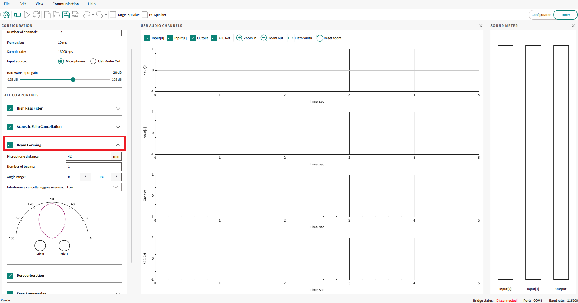
Although the Beam forming is an important part of the audio processing pipeline, it is still an optional component in the PSOC™ Edge MCU audio and voice use cases, as certain applications with memory and processing constraints may require the disabling of various components.
Therefore, the Beam Forming component can be enabled/disabled using a check box in the AFE Configurator GUI tool, as highlighted in
Figure 12
.
Figure 12.
Enabling/disabling Beam Forming in AFE Configurator
Once enabled, there are various parameters that can be configured for the Beam Former component. A snapshot of the user-configurable parameters for the beam Forming module from the AFE Configurator tool is shown in
Figure 13
Figure 13.
Beam Forming parameters
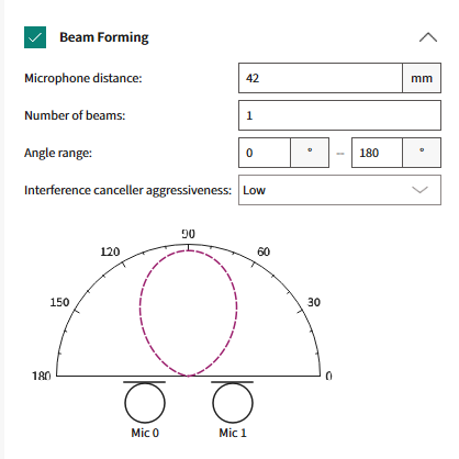
The following are the parameters:
Microphone distance (mm)
Refers to the distance in mm between the locations of the two-microphone array
Valid range: 20 mm to 100 mm
Number of beams
Refers to the number of main lobes for the Beam Forming system
Valid range: 1 to 16 beams
Angle Range (degrees)
Refers to the range of angles (in degrees) for the Beam Forming system. This restricts the beams within this range of angles
Figure 14.
Beam Forming Angle Range
The green highlighted arc denotes the Beam Forming area where the beams (as per the number of beams configured in the previous parameter) will be symmetrically placed
Two parameters – Angle1 and Angle2 (as shown in
Figure 14
)
Valid range: 0° to 180°
Interference Canceller
Refers to the aggressiveness of the final Beam Forming weight optimization algorithm discussed in the previous section
Valid range: low, medium, and high
Beam Forming graph
In the AFE Configurator tool, a graph is shown for the user-configured parameters that are updated in real-time as the configuration changes. This graph provides a very intuitive way to visualize how the parameters affect the final Beam Forming output.
The visualizations for some of the combinations of the parameters are shown below as examples. This helps to understand how the parameters "
Number of beams
" and "
Angle Range
" affect the final Beam Forming output. Note that these example configurations are intended to show how the parameters affect the beams and the corresponding graphs. These configurations may not be applicable for the real-world audio and voice use cases.
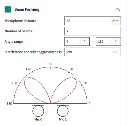
1 beam in between 0° and 180°
Figure 15.
Visualization with one beam

2 beams in between 0° and 180°
Figure 16.
Visualization with two beams
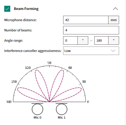
4 beams in between 0° and 180°
Figure 17.
Visualization with four beams
In summary, the required number of beams (based on the "
Number of beams
" parameter) are placed in a symmetrically centered method in the arc area (based on the "
Angle Range
" parameter) between Angle 1 and Angle 2, as shown in
Figure 14
.
Dereverberation
Introduction to Dereverberation
Dereverberation is a critical process in the domain of audio signal enhancement aimed at mitigating the effects of reverberation, the persistence of sound in an enclosed space after the original sound is produced.
Reverberation occurs when sound waves reflect off surfaces, such as walls, ceilings, and objects, creating a complex superposition of delayed signals that can blur the clarity and intelligibility of the audio. In modern applications, such as teleconferencing and voice-activated devices, the clarity of the audio signal is paramount. As such, the presence of reverberation can severely hamper the performance of these applications, leading to decreased speech recognition accuracy and user dissatisfaction.
Figure 18.
Illustration of Reverberation
Dereverberation technologies strive to extract the 'clean' audio signal by suppressing these multiplicative reflections, thereby enhancing the user experience by delivering clearer and more distinct audio. In spaces with significant reverberation, speech can become less intelligible, and the performance of acoustic systems that rely on clear signals can be heavily affected, for instance, Echo Cancellation, and Beam Forming. Effective Dereverberation enhances the direct sound, which is critical for listeners and for downstream audio processing algorithms.
Principles of Reverberation
Understanding the principles of reverberation is key to developing Dereverberation techniques. Reverberation is a natural acoustic phenomenon characterized by the persistence of sound in an environment due to a series of reflections from surrounding surfaces.
When a sound is produced, it travels through the air and bounces off objects, with each reflection arriving at the listener's ear at slightly different times. These delayed signals combine to create the reverberant sound field, which is perceived as a prolongation of the sound. The Dereverberation process removes the multipath distortions from the audio signal.
The characteristics of this reverberation are largely determined by the size and shape of the room, the reflective properties of the surfaces, and the absorption coefficients of materials within the space. The decay of the reverberant sound over time is quantified by a metric known as the reverberation time (RT60), which is the time it takes for the sound to drop 60 decibels from its initial level. A comprehensive understanding of these principles is critical for designing algorithms that can effectively distinguish between direct and reverberant sound components and apply the necessary processing to minimize the impact of the latter.
Dereverberation component
Dereverberation techniques typically rely on signal processing techniques that model the reverberation and attempt to invert or suppress it. These techniques include inverse filtering, where the impulse response of the room is estimated and an inverse filter is designed to counteract the reverberation effect. In the PSOC™ Edge MCU audio pipeline, the Dereverberation component is placed in between the Beam Forming and Echo Suppression component, as highlighted in
Figure 19
. The echo-cancelled output passes through the Beam Forming and is then fed in as input to the Dereverberation component and its output is fed into the next stage, which is the echo suppression component.
Figure 19.
Dereverberation component in the PSOC™ Edge MCU audio pipeline
For the PSOC™ Edge MCU audio and voice use cases, a frame-based Linear Prediction Inverse Modulation-Transfer-Function (LP-MTF) algorithm is used for Dereverberation.
Linear Prediction Inverse Modulation-Transfer-Function (LP-MTF) based Dereverberation is a method that combines the principles of linear prediction (LP) with the modulation transfer function (MTF) to reduce the effects of reverberation in audio signals. In essence, it is a signal processing approach that aims to enhance the original, direct sound by modeling and counteracting the acoustic transfer function of the environment.
Combining the two concepts, the LP-MTF technique involves first applying LP to the reverberant signal to obtain an estimate of the direct sound and then using the inverse of the estimated modulation transfer function to correct the signal. This process aims to restore the lost modulations due to reverberation and to recover the clarity and details of the original audio.
The steps typically involved in LP-IMTF-based Dereverberation are as follows:
Signal analysis:
The reverberant audio signal is analyzed using linear prediction to estimate the speech parameters, effectively separating the vocal tract's signal (direct sound) from the reverberation
MTF estimation:
The characteristics of the reverberant environment are estimated to determine how they affect the signal's modulation spectra
Inverse filtering:
An inverse filter based on the estimated MTF is designed and applied to the signal to compensate for the effects of reverberation, particularly focusing on the restoration of high-frequency modulations that carry crucial speech information
Signal synthesis:
Finally, the enhanced speech parameters obtained after inverse filtering are used to synthesize the Dereverberated signal
This technique can be particularly effective for speech signals, where the linear predictive coding model is a well-established tool for speech analysis and synthesis. However, like all Dereverberation techniques, LP-MTF has its challenges, including the accurate estimation of the MTF and the LP model, which can be sensitive to the type and level of reverberation present in the environment. It is also worth noting that LP-MTF, being a model-based approach, may require careful tuning to work effectively across different reverberant conditions. An intelligent algorithm is used on the PSOC™ Edge MCU for the dynamic update of the filters to overcome these challenges.
Configuration parameters
Similar to the previously mentioned components, even the Dereverberation component is an optional component. Enable or disable the dereverberation block using the check box in the AFE Configurator, as highlighted in
Figure 20
.
Figure 20.
Enable/disable Dereverberation in AFE Configurator
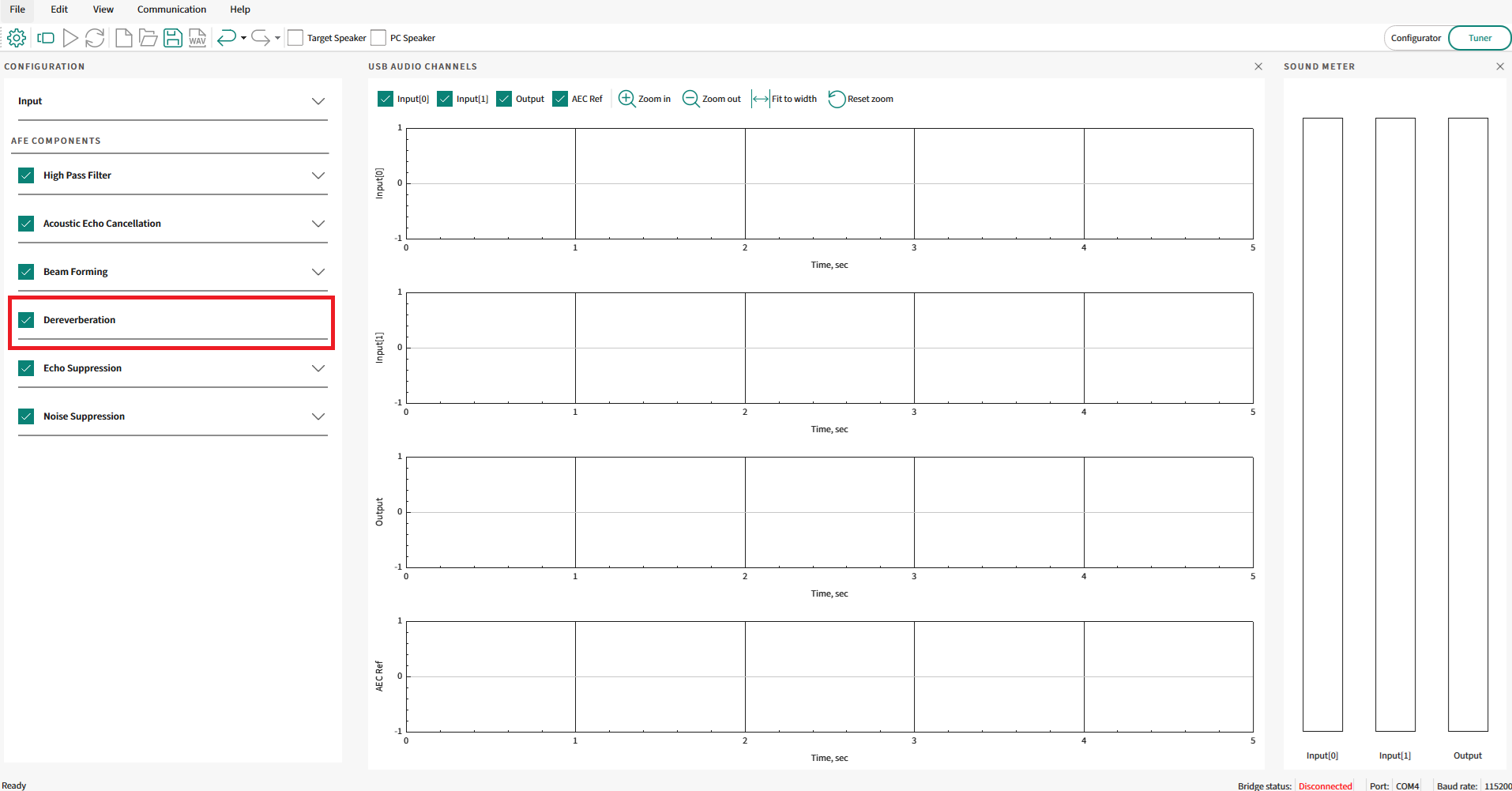
There are no user-configurable parameters within the Dereverberation component once enabled. The algorithms are tuned and tested to work for the PSOC™ Edge MCU audio and voice use cases without needing any parameters to be configured.
Noise Suppression
Introduction to Noise Suppression
Noise Suppression is a fundamental aspect of audio signal processing, particularly essential in enhancing the clarity of captured audio from a single/dual microphone in noisy environments. The primary objective of noise suppression is to discern and attenuate unwanted ambient sounds, such as traffic, HVAC systems, and background conversations, while preserving the original signal's integrity, typically speech. These unwanted sounds can greatly affect the user experience, impairing communication, and reducing the efficacy of voice-controlled systems. As such, noise suppression is not merely a feature but a necessity in modern audio technology, where clear audio is paramount, from telecommunication to virtual assistants, and beyond. The sophistication of noise suppression algorithms plays a critical role in the performance of these systems, directly impacting their usability and effectiveness in real-world conditions.
Principles of Noise Suppression
Noise Suppression in audio processing is a multifaceted algorithm aimed at diminishing the presence of unwanted ambient sounds within a signal. The task is complex, as noise can intrude in various ways, often overlapping with the important components of the signal in both frequency and time. In audio processing, the noise suppression begins with a detailed analysis of the audio signal's characteristics. Speech signals follow certain predictable patterns, including harmonics and formant structures, which are not typically mirrored in noise. These patterns provide a basis for distinguishing speech from noise.
Noise estimation is a critical next step where the noise profile is continuously assessed and quantified. This process is pivotal for the adaptive nature of noise suppression algorithms, which must adjust to the noise spectrum's fluctuations, especially in the presence of non-stationary noises. Techniques such as spectral averaging, where the noise floor is estimated by averaging the spectral density over a period when speech is absent, are commonly utilized.
Once the noise is estimated, the spectral subtraction approach comes into play. Here, an estimate of the noise spectrum is subtracted from the signal's spectrum. Avoid over-subtraction, which can lead to artifacts and a degradation of speech quality.
In addition to spectral subtraction, adaptive filters like the Wiener filter seek to construct a filter that applies gain to frequencies dominated by speech while suppressing those dominated by noise, thereby minimizing the mean square error of the output signal compared to the original, clean signal.
Finally, the application of psycho-acoustic principles ensures that noise suppression algorithms align with the human auditory system's perception, prioritizing the reduction of noise components that most affect the listener's experience. Post-processing steps are also crucial to mitigate any artifacts introduced during noise suppression, ensuring that the resulting audio maintains naturalness and intelligibility for the end user.
The overarching goal of these principles is not merely to suppress noise but to do so while preserving the quality of the desired signal. The interplay between noise reduction and audio fidelity is delicate and requires a careful balance, which forms the crux of noise suppression in the field of audio processing.
Noise Suppression component
In the PSOC™ Edge MCU audio pipeline, the Noise Suppression component is placed at the end, after the Echo Suppression component, as highlighted in
Figure 21
. The echo-cancelled, beamformed, dereverberated, and echo-suppressed output is fed in as the input to the Noise Suppression component.
Figure 21.
Noise Suppression component in the PSOC™ Edge MCU audio pipeline
As the two-channel microphone data is already combined into single-channel data using the required Beam Forming component, the input data available to the Noise Suppression component is single-channel audio data. Therefore, a single-channel Noise Suppression algorithm is applied in this case.
The principles of single-channel Noise Suppression revolve around the characterization and differentiation of noise from the desired audio signal. The process begins with the assumption that speech has a structured pattern, exhibiting certain periodicity and harmonic structures, whereas noise tends to be more random or has a consistent spectral profile that can be modeled over time. Noise Suppression algorithms exploit these differences through various signal processing techniques.
Statistical models, such as the Wiener filter, uses probabilistic approaches to predict the speech signal and minimize the mean square error between the noisy input and the estimated clean signal. The underlying goal of these principles is to achieve a balance between noise reduction and the preservation of the natural quality of the speech signal, ensuring that the desired audio is transmitted clearly and intelligibly to the listener or the next stage of the audio processing pipeline.
After the primary Noise Suppression algorithm has been applied, post-processing steps are necessary to improve the quality of the signal using techniques like weighted overlap-add synthesis. The output from the process is clean audio data with stationary background noise suppressed, based on the configured gain setting.
The Noise Suppression algorithm is available as part of an AE Machine Learning-based model that executes out of Arm® Ethos-U55 and is known as "Deep Subband Noise Suppression".
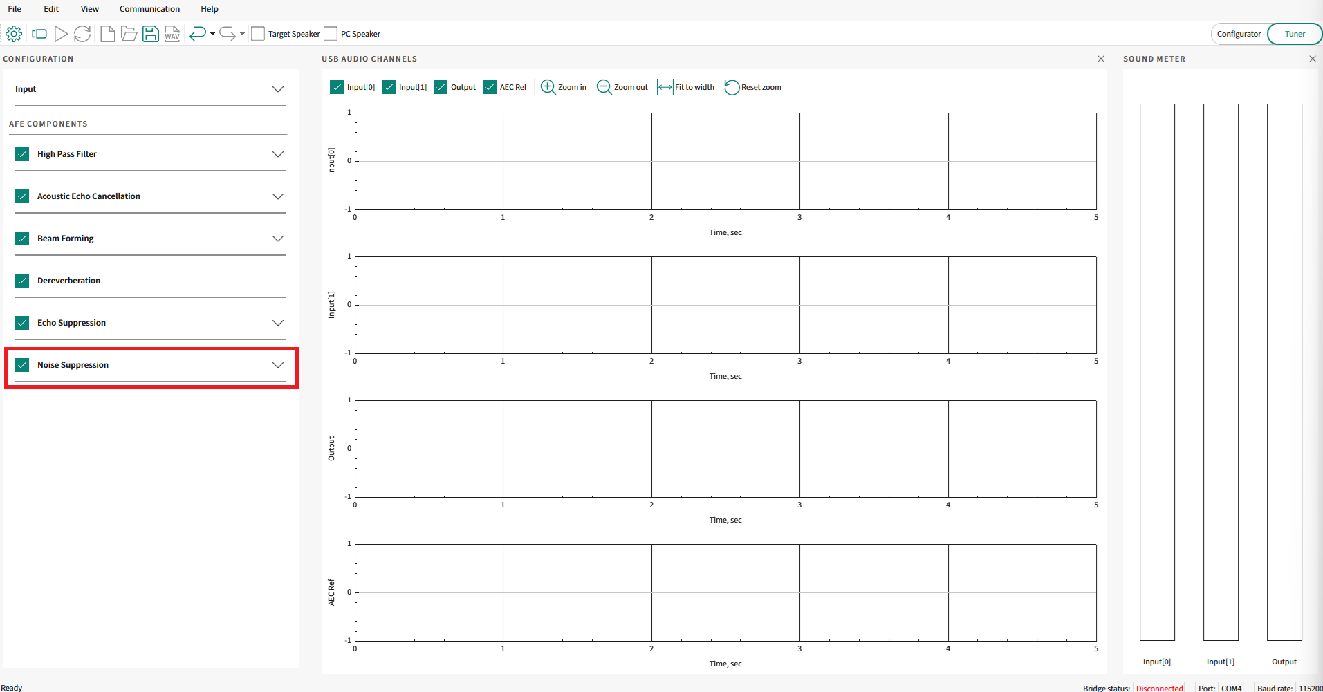
Configuration parameters
Similar to the previously discussed components, even the Noise Suppression component is an optional component. Enable or disable the Noise Suppression block using the check box in the AFE Configurator, as highlighted in
Figure 22
.
Figure 22.
Enable/disable Noise Suppression in AFE Configurator
Once enabled, configure one parameter for the Noise Suppression component. The user-configurable parameter for the Noise Suppression component from the AFE Configurator tool is shown in
Figure 23
.
Figure 23.
Noise Suppression parameter

The following is the parameter:
Noise suppressor (dB)
:
Refers to the noise suppressor intensity in decibels (dB)
Valid range: 0 dB to 20 dB
To increase the aggressiveness of the Noise Suppression component, increase the above parameter value with the maximum noise suppression being 20 dB. Increase/decrease the parameter by integer amounts in the dB scale between 0 dB and 20 dB as per the application requirements.
Audio Enhancement (AE) operation
This section explains the complete flow of using Audio Enhancement code example 1 and its various modes.
Audio Enhancement code example
Use the PSOC™ Edge MCU: DEEPCRAFT™ Audio Enhancement application code example 1 to know about Audio Enhancement on the PSOC™.
It supports audio capture via onboard pulse-density modulation (PDM) microphones and also allows audio streaming via USB Audio Class (UAC) from PC, which can be played on the onboard speakers. The audio streamed over USB is played on the onboard speaker and is also considered as Acoustic Echo Cancellation (AEC) reference if the AEC algorithm is enabled.
The PDM data and AEC reference data (if present) are sent to the AFE middleware, which uses audio algorithms (Beam Forming, Noise Suppression, AEC/Echo Suppression, Dereverberation, and High Pass Filter) and processes the PDM data. When no data is streamed from PC to device, the code example will be still executing algorithms of AFE (if they are enabled, except AEC processing) on the PDM data. The AE-processed data is also sent back to the PC via USB Audio Class, which enables to understand and visualize the processing of the audio input.
The code example is FreeRTOS-based with support for Arm® and LLVM compilers.
To understand PSOC™ Edge MCU: DEEPCRAFT™ Audio Enhancement application code example 1 , see the
README.md
and
ae_design_guide.md
files in the code example
1
.
To setup the code example on the kit, see the DEEPCRAFT™ Audio Enhancement quick start guide
1
.
By default, the audio-voice-core library is restricted to run only for 15 minutes. Contact
Infineon support
to get the licensed version of the audio-voice-core library. The code example
1
contains details on how to switch between a licensed and unlicensed version of an audio-voice-core library.
Modes of operation
The code example supports two modes:
FUNCTIONAL mode: In this mode, the PSOC™ Edge device enumerates as a 1-channel USB Audio Class (UAC) microphone on the PC. By default, the PSOC™ Edge device sends the AE processed data back to the PC. On pressing the user button (USER-BTN1) on the kit, it switches to unprocessed data. In this mode, you can observe the difference between processed and unprocessed data on the PC. The blue LED on the kit notifies about the type of data sent over USB. Blue LED on indicates that processed data is sent and blue LED off indicates that unprocessed data is sent
TUNING mode: In this mode, the PSOC™ Edge device enumerates as a 4-channel USB Audio Class microphone on the PC. This mode is ideal to be used with AFE Configurator, which enables users to configure which data will be sent via the 4-channels. It helps in debugging/tuning the audio pipeline, tuning the AFE middleware parameters and visualizing different algorithm output, thereby enabling you to understand the effects of processing
The code example requires one more USB cable to be connected to the kit for the USB Audio Class (UAC) communication. This USB cable has to be connected to the device USB port on the PSOC™ Edge Kit.
Figure 24.
USB device connection
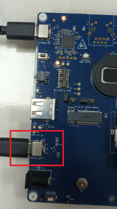
On building and flashing the code example, the PSOC™ Edge MCU device will enumerate as USB Audio Class microphone and speaker to the PC. Depending on the mode of operation, it would be either a 1 channel microphone or a 4 channel microphone as explained in the above modes.
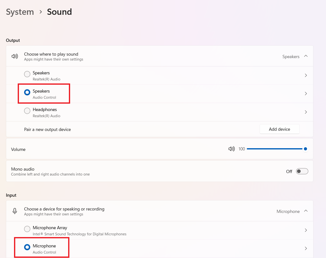
The name of USB enumerated devices (both speaker and microphone) will be
Audio Control
.
Ensure that the PSOC™ Edge MCU device is detected by the PC as shown in
Figure 25
.
Figure 25.
System sound settings
Operational flow and visualization
Operation in FUNCTIONAL mode
By default, the PSOC™ Edge MCU: DEEPCRAFT™ Audio Enhancement application code example
1
is configured in FUNCTIONAL mode. You can change the mode between FUNCTIONAL/TUNING in the
common.mk
file.
File: common.mk

# AE mode :
# FUNCTIONAL    - Demonstrates Audio Enhancement processing with single USB channel to PC.
# TUNING        - Demonstrates Audio Enhancement processing and tuning with quad USB channels to PC.

CONFIG_AE_MODE=FUNCTIONAL
See the PSOC™ Edge MCU: DEEPCRAFT™ Audio Enhancement application code example
1
on the steps to build/flash the code example to the kit.
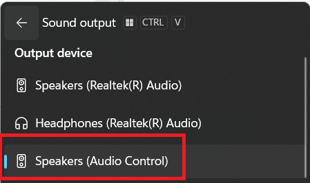
Ensure to choose the output audio device of the PC as "Audio Control".
Figure 26.
Output audio device
Play any music or speech audio from Internet or local files using Media Player or any audio playback tool. The code example also includes a default test stream located at
ae_test_stream/ae_test_stream.wav
.
This audio will be streamed via USB to the PSOC™ Edge device and played on the onboard speaker. Streaming audio is required only if AEC is enabled.
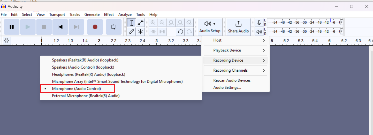
Open Audacity and ensure to choose the
Microphone (Audio Control)
and the number of channels as mono.
Figure 27.
Audacity microphone settings
Click
Record
on Audacity to start recording from a PSOC™ Edge device. PSOC™ Edge device uses its PDM microphones to start capturing user speech and background noise.
Observe the blue LED on the PSOC™ Edge kit, if the LED is on then the audio stream that is being recorded is the AE processed data.
Figure 28.
LED status
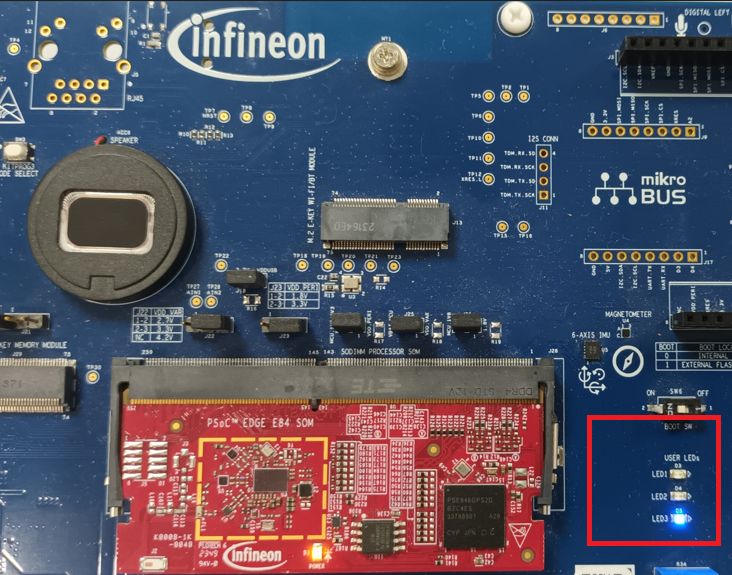
Press the
User Button 1 (USER BTN1)
on the kit to toggle the LED. If the LED is off, then the audio stream that is being recorded will be unprocessed data.
In Audacity, the recorded audio will change accordingly whenever
USER BTN1
is pressed. For example,
Figure 29
shows processed audio and unprocessed audio that gets switched based on
USER BTN1
.
Figure 29.
Audio stream (processed/unprocessed data)
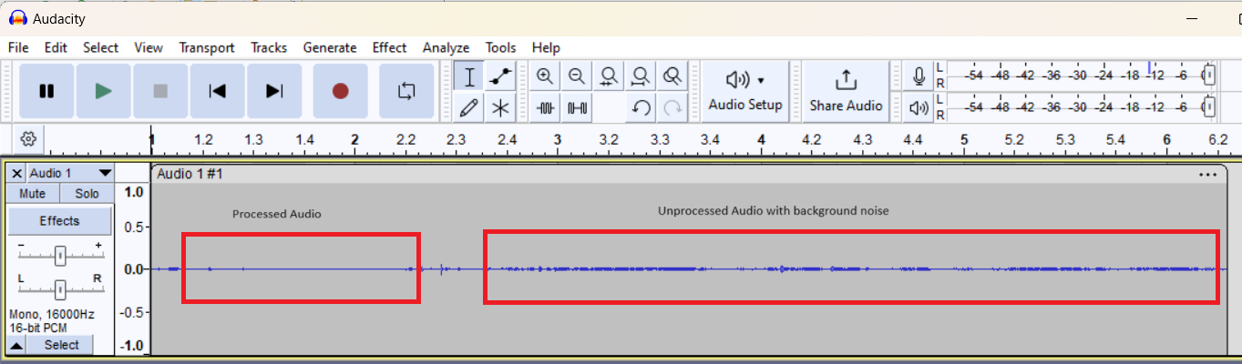
If unprocessed audio is being streamed it will have microphone data with user speech, background noise, etc. When processed audio is being streamed, then depending on the AE components the processed data will have the relevant processing done. For example, Noise Suppression.
Operation in TUNING mode
In TUNING mode, the PSOC™ Edge device will enumerate as a quad-channel audio mic to the PC. This enables users to visualize the streams and use AFE Configurator for tuning/debugging.
To choose TUNING mode:
File: common.mk
# AE mode :
# FUNCTIONAL    - Demonstrates Audio Enhancement processing with single USB channel to PC.
# TUNING        - Demonstrates Audio Enhancement processing and tuning with quad USB channels to PC.

CONFIG_AE_MODE=TUNING
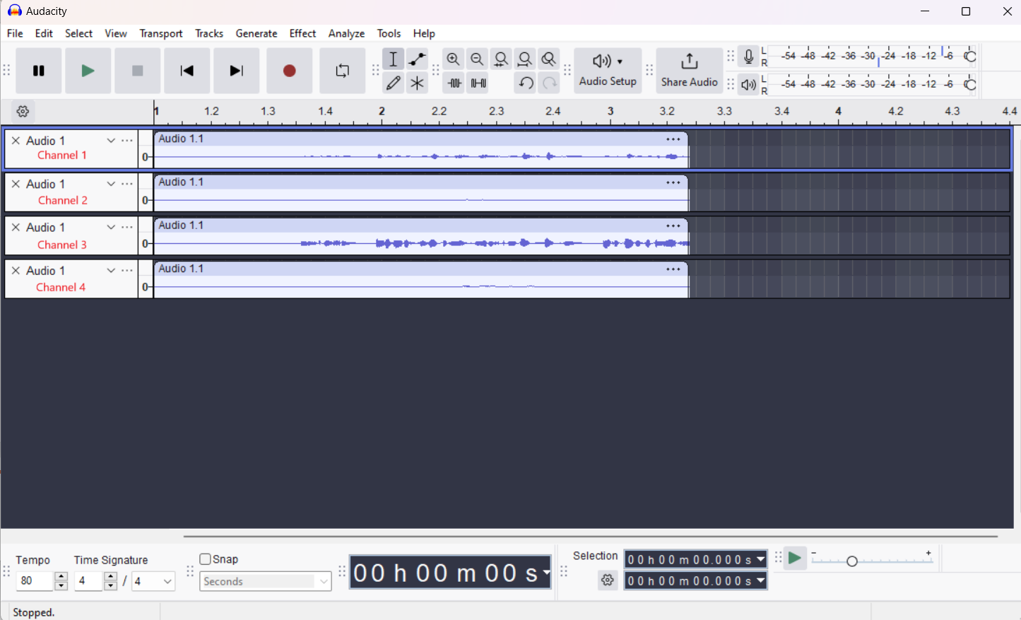
For the 4 channels to display in Audacity, ensure to choose the following settings:
Figure 30.
Audacity interface settings
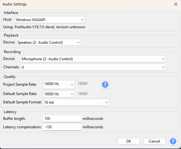
And the number of channels to be chosen is 4.
On recording, the PSOC™ Edge device will stream 4 channels. These 4 channels are decided by the settings chosen from AFE Configurator.
Figure 31.
Choosing the quad channels in AFE Configurator
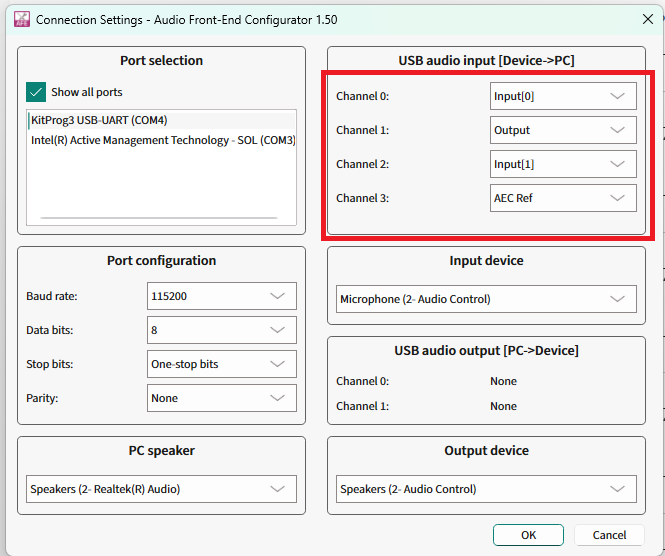
After saving the configuration and flashing the kit, the 4 channels will have the required data streamed via USB to the PC.
Figure 32.
Quad channel output
Audio Enhancement (AE) tuning
This section shows how to use Audio Front End (AFE) Configurator to tune the components of Audio Front End (AFE) middleware.
Tuning via Audio Front End Configurator
The Audio Front End Configurator enables to customize the AFE components running on the PSOC™ Edge device.
The AFE Configurator can open and existing AFE Configurator project file or create a new project file. In the PSOC™ Edge MCU: DEEPCRAFT™ Audio Enhancement application code example
1
, the AFE project file is available in the following path.
C:\Users\[username]\Infineon\Tools\DEEPCRAFT-Audio-Enhancement-Tech-Pack\tools\audio-fe-configurator
To open this project file, select the
Audio FE Configurator
under
proj_cm55
in Eclipse IDE.
Figure 33.
AFE Configurator

Other options for opening the
.mtbafe
project are as follows:
In case if you are not using Eclipse IDE, open the
proj_cm55
folder in the modus-shell and run the
make
audio-fe-configurator
command
Open the
ae_configuration.mtbafe
via
audio-fe-configurator.exe
located in:
C:\Users\[username]\Infineon\Tools\DEEPCRAFT-Audio-Enhancement-Tech-Pack\tools\audio-fe-configurator
It will open the AFE Configurator project as shown in
Figure 34
Figure 34.
AFE Configurator GUI

You can change the parameters of each AFE component and the AFE Configurator generates the following files:
cy_afe_configurator_settings.c
cy_afe_configurator_settings.h
These files contain the AFE filter settings and other options, such as which components are enabled. These files are available under the
GeneratedSource
folder at the same path as the AFE project file. For example:
proj_cm55\source\audio_enhancement_application\audio_enhancement\GeneratedSource
The AFE middleware requires these two files. In the PSOC™ Edge MCU: DEEPCRAFT™ Audio Enhancement application code example
1
the build system automatically compiles these files from the
GeneratedSource
folder.
You can choose the microphone type between:
Microphone: This chooses a PDM microphone as input to the code example. The stereo/mono mode of the PDM microphone can also be configured from AFE Configurator. PDM microphone will be used for capturing user speech while the data streamed via USB to the kit will be used as AEC reference
USB Audio Out: This chooses USB as the input to the code example and the PDM microphone is disabled. This option is useful for benchmarking AFE middleware components or in other code examples for inferencing benchmarking
The AFE Configurator supports dynamic tuning of selected parameters. For parameters that do not support dynamic tuning, compile the generated files and flash to the PSOC™ Edge MCU device each time.
provides the full list of parameters.
Filter type | Parameter name |
|---|---|
Input | Number of channels |
Frame size (ms) | |
Sample rate (sps) | |
Hardware input gain (dB) | |
Input source | |
Baud rate | |
Target speaker | |
High Pass Filter | Enable high pass filter |
Cut-off frequency (Hz) | |
Acoustic Echo Cancellation | Enable echo cancellation |
Echo tail (ms) | |
Bulk delay (ms) | |
Beam Forming | Enable Beam Forming |
Microphone distance (mm) | |
Number of beams | |
Angle range start (degrees) | |
Angle range end (degrees) | |
Interference canceller aggressiveness | |
Dereverberation | Enable Dereverberation |
Echo Suppression | Enable Echo Suppression |
Enable suppressor aggressiveness | |
Noise Suppression | Enable Noise Suppression |
Noise suppressor level (dB) | |
Audio channels | Channel 0 |
Channel 1 | |
Channel 2 | |
Channel 3 |
Static parameters
lists the static parameters.
Filter type | Parameter name |
|---|---|
Input | Number of channels |
Frame size (ms) | |
Sample rate (sps) | |
Input source | |
Baud rate | |
Target speaker | |
High Pass Filter | Enable high pass filter |
Cut-off frequency (Hz) | |
Acoustic Echo Cancellation | Echo tail (ms) |
Beam Forming | Microphone distance (mm) |
Number of beams | |
Angle range start (degrees) | |
Angle range end (degrees) | |
Interference canceller aggressiveness |
To take the effect of static parameters, flash the settings to the PSOC™ Edge MCU device. The steps are as following,
Use the AFE Configurator project file
Adjust the static parameters
Save the AFE Configurator project that creates the cy_afe_configurator_settings.c and cy_afe_configurator_settings.h files
Build and flash the firmware to the device
Dynamic parameters
Table 4
lists the dynamic parameters.
Filter type | Parameter name |
|---|---|
Input | Hardware input gain (dB) |
Acoustic Echo Cancellation | Enable echo cancellation |
Bulk delay (ms) | |
Beam Forming | Enable Beam Forming |
Interference canceller aggressiveness | |
Dereverberation | Enable Dereverberation |
Echo Suppression | Enable Echo Suppression |
Enable suppressor aggressiveness | |
Noise Suppression | Enable Noise Suppression |
Noise suppressor level (dB) | |
Audio channels | Channel 0 |
Channel 1 | |
Channel 2 | |
Channel 3 |
To tune the dynamic parameters, use the AFE Configurator. The AFE Configurator uses UART to send text commands to the PSOC™ Edge MCU device and to receive the response.
The UART used for AFE configuration is KitProg3 USB-to-UART, which is the same UART that is used for displaying UART logs on the terminal.
For tuning, close any open terminal such as Tera Term, Putty, etc. that might be using the same UART port.
Open the AFE Configurator project and ensure that the correct COM port is chosen in AFE Configurator.
Figure 35.
Connection settings
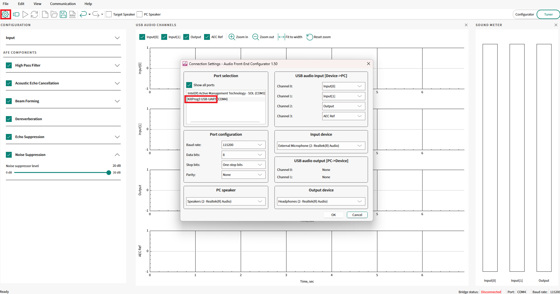
Choose the correct KitProg3 USB-to-UART port that is displayed. For example, COM4.
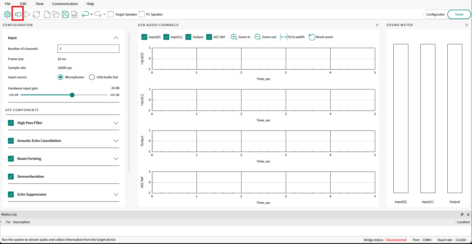
Connect to the PSOC™ Edge MCU device as shown in
Figure 36
.
Figure 36.
Connect to device
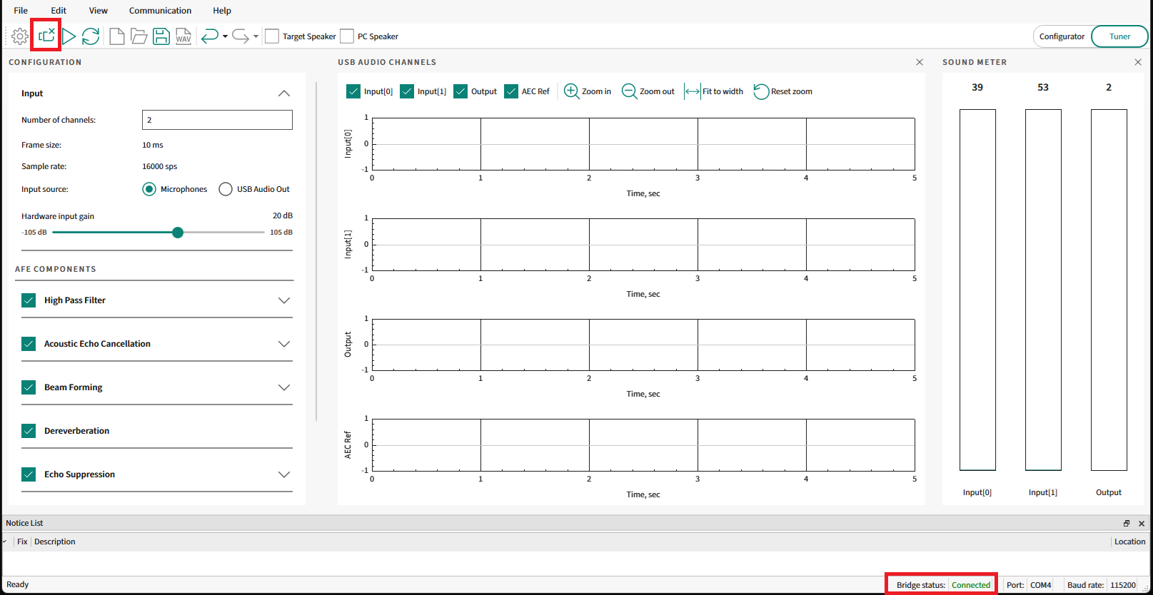
Ensure that the
Bridge status
shows as
Connected
that confirms that the PSOC™ Edge MCU device is connected with the AFE Configurator.
Figure 37.
AFE connected status
Adjust any parameter that can be dynamically tuned. For example, Noise Suppression is a dynamic parameter. Disable the Noise Suppression component as shown in
Figure 38
and select
Sync filter settings
.
Figure 38.
Dynamic configuration
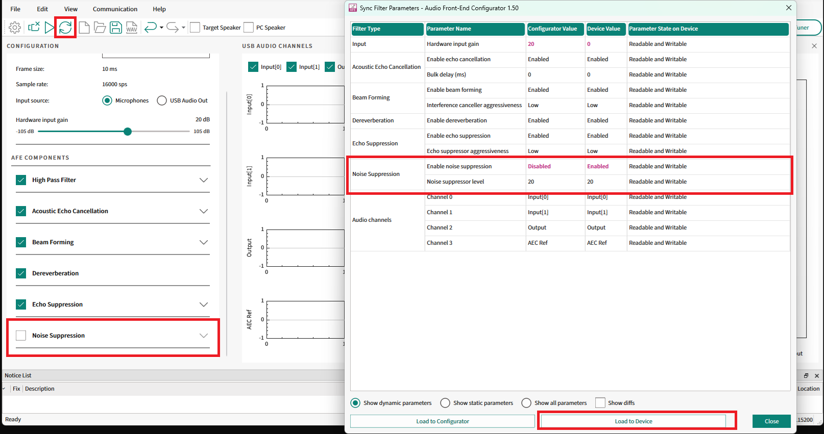
This will open the
Sync Filter Parameters
window. Select
Load To Device
to load the settings to the device.
If the sync is successful, the effects of the tuning will take effect immediately.
Note that the dynamic configuration will be possible only if the configuration flashed into the device has the component enabled, else you need to enable the component and flash the configuration to the device.
For example, if the default configuration flashed to the device has no
Noise Suppression
enabled, then dynamically configuring this component via AFE Configurator is not possible. So flash it first by enabling it, then it will be possible to dynamically control this.
USB streaming options
The PSOC™ Edge MCU: DEEPCRAFT™ Audio Enhancement application code example (see
References
) has options to stream data from the PSOC™ Edge MCU device or to the device via USB Audio Class (UAC).
As explained in the
Audio Enhancement (AE) operation
section, the code example
1
can function in TUNING or FUNCTIONAL mode.
The audio from the device can be visualized via the Audacity tool.
However, the AFE Configurator also has options to receive and send audio data via USB Audio Class.
To use this option with AFE Configurator, configure the code example in TUNING mode and flash to the device.
File
:
common
.
mk CONFIG_AE_MODE
=
TUNING
Open the AFE Configurator project and select the
Connection Settings
.
The USB audio input section contains a drop down list, which can be used to select which data should be streamed on the individual channels from the device to the PC via USB Audio Class.
Figure 39.
USB channel options in AFE Configurator

Save the settings and flash to the PSOC™ Edge MCU device.
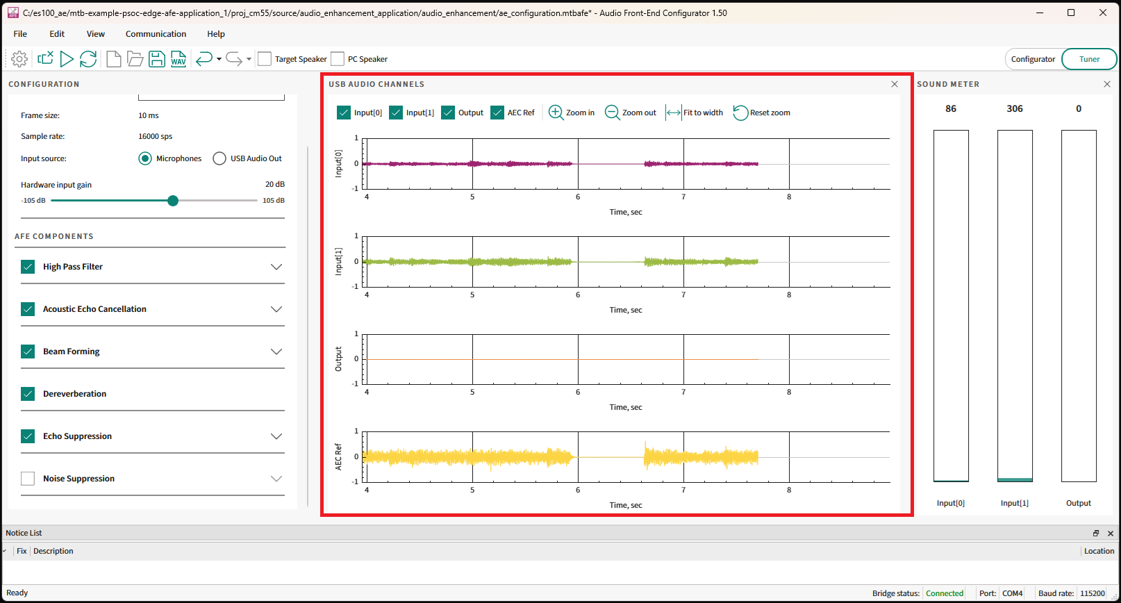
Connect the AFE Configurator to the device and select the
Play
button to record audio from the device.
Figure 40.
AFE Configurator - Play button

The AFE Configurator will display the 4 channels of audio data captured from the device.
Figure 41.
AFE Configurator - USB Audio Channels
After some time, select the
Stop
button.
Figure 42.
AFE Configurator - Stop button

Use the save recording button to save the quad channel audio.
Figure 43.
AFE Configurator - Save button

The saved file can also later be opened with Audacity for further analysis.
See the
ae_design_guide.md
file in the PSOC™ Edge MCU: DEEPCRAFT™ Audio Enhancement application code example
1
for more options on using Audacity/DEEPCRAFT™ Studio to visualize the streams.
Audio Enhancement (AE) benchmarking
The Audio Front End middleware components can be individually bench marked by feeding test streams and then use the AE processed data to calculate the speech quality scores.
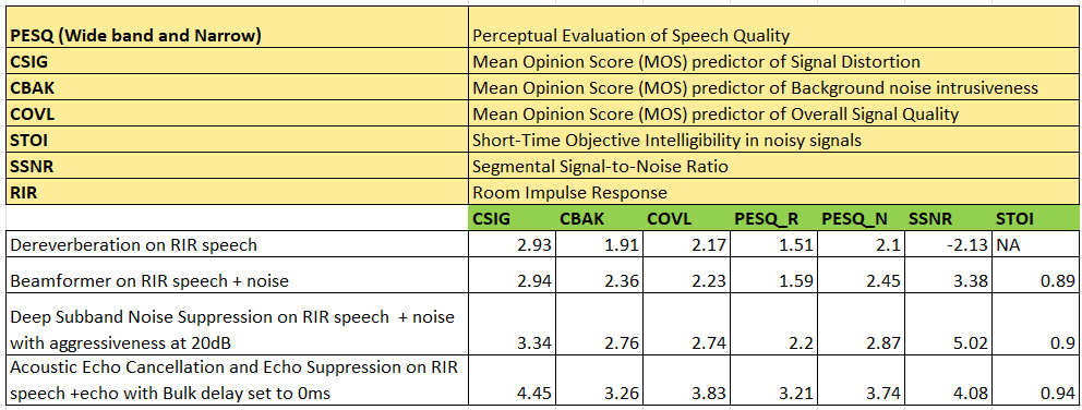
Benchmark scores
shows the speech quality scores of individual Audio Front End component.
Figure 44.
Speech quality scores
Procedure to reproduce the scores
The following are a high-level overview of calculating speech quality scores.
Note:
To calculate the speech quality scores on the kit, you can generate your own test streams and see the
Deep Noise Suppression Challenge
repo on GitHub for creating the Python scripts.
Configure the PSOC™ Edge MCU: DEEPCRAFT™ Audio Enhancement application code example
1
in FUNCTIONAL mode (set
CONFIG_AE_MODE=FUNCTIONAL
in the
common.mk
file) and choose the input as USB Audio Out in AFE Configurator
Enable the AFE component to benchmark in AFE Configurator and disable all other components. For example, to benchmark Noise suppression, select only this component in the AFE Configurator
Save the configuration and flash to the device. There should be a set of test streams for benchmarking each AFE component. The test streams can be mixed with Room Impulse Response (RIR) and noise depending on the AFE component to be benchmarked. Each test stream should also have an equivalent clean stream to serve as a reference
Run a Python script or code on the PC to stream these test streams one by one to the device and record the AE-processed data that match to each input stream on the PC
Run a Python script to take the AE-processed data and clean data as input and calculate the score
For AEC benchmarking, the test streams should have speech in one channel and AEC reference in the second. Set
#define AEC_QUALITY_MODE (1)
in the
audio_data_feed.c
file for AEC benchmarking
Integration of Audio Enhancement (AE) to sample audio pipeline
The PSOC™ Edge MCU: DEEPCRAFT™ Audio Enhancement application code example
1
serves as a reference on the design of the audio pipeline with Audio Enhancement. It can be referred for creating custom audio pipelines with Audio Enhancement.
The Audio Enhancement runs only on the high-performance core (Arm®Cortex®-M55) of PSOC™ Edge MCU. It utilizes Arm® Helium technology, which is also called as "Arm® M-Profile Vector Extension (MVE)". It is supported in Arm®v8.1-M architecture and offers significant improvement in ML and DSP processing.
The Audio Enhancement should be available after the microphone acquisition in the audio pipeline. The Audio Enhancement processed data should be sent for further actions, such as inferencing, streaming, etc.
shows how the Audio Enhancement should be available in the audio pipeline. It shows the complete pipeline where the microphones are controlled by the CM55 core.
Figure 45.
Audio pipeline
Code flow overview
The PSOC™ Edge MCU: DEEPCRAFT™ Audio Enhancement application code example
1
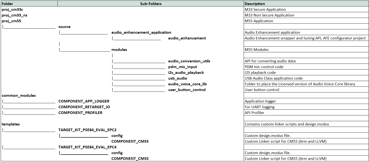
is organized as shown in the following figure folder structure.
Figure 46.
Folder structure
shows the code flow of the sequence diagram.
Figure 47.
Code flow
The Audio Enhancement requires 10 ms of audio samples which are sampled at 16 kHz. In the
Figure 47
diagram, the user speech is captured via a PDM microphone. The Audio Enhancement library is called in the PDM ISR context.
The AEC reference is collected from the USB task and fed into the Audio Enhancement library. However, depending on the use case, this AEC reference can also arrive from a file or from another task, etc. For example, the Local Voice Music Player code example has the flow where the AEC reference arrives from another task and not via USB.
The Audio Enhancement library has its own FreeRTOS task inside and uses the fed audio data and does the processing. It invokes a callback function through, which the Audio Enhancement processed data is available to the application. This data can be further sent to inferencing task (if present) or to USB task for streaming it back to the PC or to Bluetooth® task (if present) for streaming over Bluetooth®.
Audio Enhancement code snippets
The following are the key changes that are required for integrating Audio Enhancement to the pipeline. For extensive details, see the PSOC™ Edge MCU: DEEPCRAFT™ Audio Enhancement application code example and its
README.md
file 1.
Makefile:
Define the following macros and enable specific components. These should be added in the
Makefile
of
CM55
project in the PSOC™ Edge MCU: DEEPCRAFT™ Audio Enhancement application code example
1
.
The AFE middleware-related macros and components are:
Path: proj_cm55/Makefile

COMPONENTS += CMSIS_DSP

DEFINES += RUN_FLOAT_FE
DEFINES += ENABLE_AFE_MW_SUPPORT
DEFINES += CY_AFE_ENABLE_TUNING_FEATURE

DEFINES+=DSNS_ENABLE_MTB_ML
COMPONENTS+=MW_DSNS_MODEL MW_MDL_DSNS MW_MDL_DSES
DEFINES+=USE_MTB_ML

ifeq ($(CONFIG_VOICE_CORE_MODE),LIMITED)
    COMPONENTS+=AVC_DEMO
endif

ifeq ($(CONFIG_VOICE_CORE_MODE),FULL)
    COMPONENTS+=AVC_FULL
endif
The AFE middleware task priority (if required based on use case) can be controlled via.
Path: proj_cm55/Makefile

DEFINES += AFE_AUDIO_PROCESSING_TASK_PRIORITY=2
The AFE middleware also relies on ML middleware and therefore, enable its related macros and components.
Path: proj_cm55/Makefile

NPU=U55
DEFINES+=ETHOSU55
COMPONENTS+=ML_TFLM
DEFINES+=TF_LITE_STATIC_MEMORY
COMPONENTS+=ML_INT16x8
DEFINES+= CY_ML_MODEL_MEM=.cy_socmem_data
NN_TYPE=int16x8
COMPONENTS+=U55
For USB Audio Class, the following are required.
Path: proj_cm55/Makefile
COMPONENTS += EMUSB
COMPONENTS += USBD_BASE
The other application-related macros and components can be added based on the code example. For example, see the
proj_cm55
/
Makefile
of the PSOC™ Edge MCU: DEEPCRAFT™ Audio Enhancement application code example
1
for application-specific configurations.
Audio Front End middleware Initialization:
Initialize the Audio Front End middleware before sending audio frames to it. The memory and buffer used by Audio Front End is to be provided by the application.
The Audio Front End uses scratch and persistent buffers, and the placement of these in memory, such as SoCMeM and Tightly Coupled Memory (TCM) will change the speed of execution of Audio Front End algorithms.
Placing scratch and persistent buffers in TCM will give the best performance. The persistent and scratch buffers are provided as static buffers whereas the other buffers are dynamically allocated.
Also, the custom linker scripts are required for the best performance. See the PSOC™ Edge MCU: DEEPCRAFT™ Audio Enhancement application code example with
ae_design_guide.md
1
that shows the MCPS performance metrics for each compiler and the location of the custom linker scripts.
shows the expected MCPS and memory requirements with all AFE components enabled for Arm® and LLVM compiler settings.
Figure 48.
Audio Enhancement memory requirements and MCPS
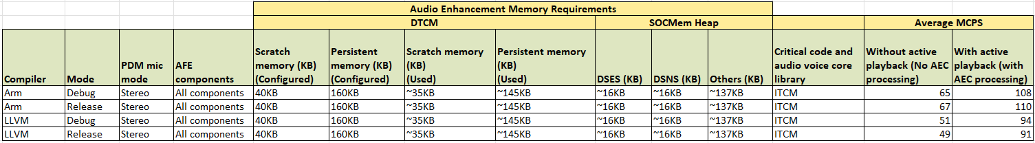
The Audio Front End middleware uses a callback to allocate these memories during initialization.
In the PSOC™ Edge MCU: DEEPCRAFT™ Audio Enhancement application code example
1
, the following snippet shows the static buffers for scratch and persistent memory.
Path: \proj_cm55\source\audio_enhancement_application\audio_enhancement\audio_enhancement.c

uint8_t ae_scratch_memory[AE_ALGO_SCRATCH_MEMORY] __attribute__((section(".dtcm_data"), aligned(4)));
uint8_t ae_persistent_memory[AE_ALGO_PERSISTENT_MEMORY] __attribute__((section(".dtcm_data"), aligned(4)));
The memory initialization callback is shown below. For the Noise Suppression and Echo Suppression, as it uses Ethos U55, it requires its memory to be 16-bit aligned.
Path: \proj_cm55\source\audio_enhancement_application\audio_enhancement\audio_enhancement.c

cy_rslt_t ae_alloc_memory(cy_afe_mem_id_t mem_id, uint32_t size, void **buffer)
{
    cy_rslt_t  ret_val = CY_RSLT_SUCCESS;
    int ae_mem_id = (int)mem_id;
    if(NULL == buffer)
    {
        return ret_val;
    }
    *buffer = NULL;
    app_ae_log("app afe alloc size %ld \r\n", (long)size);
    /* If size equal ZERO, no allocation required */
    if (size == 0)
    {
        app_ae_log("No allocation as size is zero \r\n");
        *buffer = &ae_temp_mem[0];
        return ret_val;
    }

    /* Allocate memory based on the memory ID */
    switch(ae_mem_id)
    {
        case CY_AFE_MEM_ID_ALGORITHM_NS_MEMORY:
        {
            app_ae_log("DSNS Memory requires %ld bytes \r\n", (long)size);
            ae_dsns_mem = calloc(size+15,1);
            if (ae_dsns_mem == NULL)
            {
                app_ae_log("DSNS memory allocation failed \r\n");
                ret_val = -1;
            }
            else
            {
                *buffer = (void *) (((uintptr_t)ae_dsns_mem+15) & ~ (uintptr_t)0x0F);
            }
            break;
        }

        case CY_AFE_MEM_ID_ALGORITHM_ES_MEMORY:
        {
            app_ae_log("DSES Memory requires %ld bytes \r\n", (long)size);
            ae_dses_mem = calloc(size+15,1);
            if (ae_dses_mem == NULL)
            {
                app_ae_log("DSES memory allocation failed \r\n");
                ret_val = -1;
            }
            else
            {
                *buffer = (void *) (((uintptr_t)ae_dses_mem+15) & ~ (uintptr_t)0x0F);
            }
            break;
        }
        case CY_AFE_MEM_ID_ALGORITHM_PERSISTENT_MEMORY:
        {
            app_ae_log("Persistent Memory requires %ld bytes \r\n", (long)size);

            if(size > AE_ALGO_PERSISTENT_MEMORY)
            {
                app_ae_log("Defaulting to heap allocation for persistent memory \r\n");
                *buffer = (void *)calloc(size,1);
                if (*buffer == NULL)
                {
                    app_ae_log("Persistent memory allocation failed \r\n");
                    ret_val = -1;
                }
            }
            else
            {
                *buffer = &ae_persistent_memory[0];
                memset(*buffer, 0 , size);
            }
            break;
        }
        case CY_AFE_MEM_ID_ALGORITHM_SCRATCH_MEMORY:
        {
            app_ae_log("Scratch Memory requires %ld bytes \r\n", (long)size);
            if(size > AE_ALGO_SCRATCH_MEMORY)
            {
                app_ae_log("Defaulting to heap allocation for scratch memory \r\n");
                *buffer = (void *)calloc(size,1);
                if (*buffer == NULL)
                {
                    ret_val = -1;
                }
            }
            else
            {
                *buffer = &ae_scratch_memory[0];
                memset(*buffer, 0 , size);
            }
            break;
        }
        default:
        {
            *buffer = (void *)calloc(size,1);
            if (*buffer == NULL)
            {
                app_ae_log("AFE memory allocation failed \r\n");
                ret_val = -1;
            }
            break;
        }
    }

    return ret_val;
}
The AFE middleware requires the AFE Configurator generated filter settings. The following code snippet shows the initialization step.
Path: \proj_cm55\source\audio_enhancement_application\audio_enhancement\audio_enhancement.c

cy_rslt_t ae_alloc_memory(cy_afe_mem_id_t mem_id, uint32_t size, void **buffer)
{
    cy_rslt_t  ret_val = CY_RSLT_SUCCESS;
    int ae_mem_id = (int)mem_id;
    if(NULL == buffer)
    {
        return ret_val;
    }
    *buffer = NULL;
    app_ae_log("app afe alloc size %ld \r\n", (long)size);
    /* If size equal ZERO, no allocation required */
    if (size == 0)
    {
        app_ae_log("No allocation as size is zero \r\n");
        *buffer = &ae_temp_mem[0];
        return ret_val;
    }

    /* Allocate memory based on the memory ID */
    switch(ae_mem_id)
    {
        case CY_AFE_MEM_ID_ALGORITHM_NS_MEMORY:
        {
            app_ae_log("DSNS Memory requires %ld bytes \r\n", (long)size);
            ae_dsns_mem = calloc(size+15,1);
            if (ae_dsns_mem == NULL)
            {
                app_ae_log("DSNS memory allocation failed \r\n");
                ret_val = -1;
            }
            else
            {
                *buffer = (void *) (((uintptr_t)ae_dsns_mem+15) & ~ (uintptr_t)0x0F);
            }
            break;
        }

        case CY_AFE_MEM_ID_ALGORITHM_ES_MEMORY:
        {
            app_ae_log("DSES Memory requires %ld bytes \r\n", (long)size);
            ae_dses_mem = calloc(size+15,1);
            if (ae_dses_mem == NULL)
            {
                app_ae_log("DSES memory allocation failed \r\n");
                ret_val = -1;
            }
            else
            {
                *buffer = (void *) (((uintptr_t)ae_dses_mem+15) & ~ (uintptr_t)0x0F);
            }
            break;
        }
        case CY_AFE_MEM_ID_ALGORITHM_PERSISTENT_MEMORY:
        {
            app_ae_log("Persistent Memory requires %ld bytes \r\n", (long)size);

            if(size > AE_ALGO_PERSISTENT_MEMORY)
            {
                app_ae_log("Defaulting to heap allocation for persistent memory \r\n");
                *buffer = (void *)calloc(size,1);
                if (*buffer == NULL)
                {
                    app_ae_log("Persistent memory allocation failed \r\n");
                    ret_val = -1;
                }
            }
            else
            {
                *buffer = &ae_persistent_memory[0];
                memset(*buffer, 0 , size);
            }
            break;
        }
        case CY_AFE_MEM_ID_ALGORITHM_SCRATCH_MEMORY:
        {
            app_ae_log("Scratch Memory requires %ld bytes \r\n", (long)size);
            if(size > AE_ALGO_SCRATCH_MEMORY)
            {
                app_ae_log("Defaulting to heap allocation for scratch memory \r\n");
                *buffer = (void *)calloc(size,1);
                if (*buffer == NULL)
                {
                    ret_val = -1;
                }
            }
            else
            {
                *buffer = &ae_scratch_memory[0];
                memset(*buffer, 0 , size);
            }
            break;
        }
        default:
        {
            *buffer = (void *)calloc(size,1);
            if (*buffer == NULL)
            {
                app_ae_log("AFE memory allocation failed \r\n");
                ret_val = -1;
            }
            break;
        }
    }

    return ret_val;
}
Feeding audio data to AFE middleware:
The Audio Enhancement feed API requires two arguments:
Input audio data at 16 kHz sampling rate and 10 ms frame size in non-interleaved format in-case of stereo audio
Acoustic Echo Cancellation reference data at 16 kHz and 10 ms frame size
If there is no audio playback on the PSOC™ Edge MCU device or if AEC is not enabled in AFE Configurator, the AEC reference can be passed as NULL.
Path: proj_cm55\source\audio_enhancement_application\audio_data_feed.c
#For Stereo mic input
ae_interface_feed(non_interleaved_audio, aec_reference);
#For mono mic input
ae_interface_feed(mic_audio, aec_reference);
Getting AFE processed data:
The Audio Front End middleware has its own FreeRTOS task and it calls a callback when the output is available. The following code snippet shows how to get the output data (output_buffer). Depending on the use case application, this output_buffer can be sent for inferencing, or to USB, etc.
Path: \proj_cm55\source\audio_enhancement_application\audio_enhancement\audio_enhancement.c

static cy_rslt_t ae_output_callback(cy_afe_t handle, cy_afe_buffer_info_t *output_buffer_info, void *user_arg)
{
    ae_output_buffer_info.output_buf = (int16_t *) output_buffer_info->output_buf;
    ae_output_buffer_info.input_buf = (int16_t *) output_buffer_info->input_buf;
    ae_output_buffer_info.input_aec_ref_buf = (int16_t *) output_buffer_info->input_aec_ref_buf;
#ifdef CY_AFE_ENABLE_TUNING_FEATURE
    ae_output_buffer_info.dbg_output1 = (int16_t *) output_buffer_info->dbg_output1;
    ae_output_buffer_info.dbg_output2 = (int16_t *) output_buffer_info->dbg_output2;
    ae_output_buffer_info.dbg_output3 = (int16_t *) output_buffer_info->dbg_output3;
    ae_output_buffer_info.dbg_output4 = (int16_t *) output_buffer_info->dbg_output4;
#endif
    audio_enhancement_process_output(&ae_output_buffer_info);
    return CY_RSLT_SUCCESS;
}
The PSOC™ Edge MCU: DEEPCRAFT™ Audio Enhancement application code example
1
also has
an audio_enhancement_interface.c
and
audio_enhancement_interface.h
files that abstracts the
audio_enhancement
API for the application. Application-specific code can be added to
audio_enhancement_interface.*
files such as profiling, etc.
For example, the
audio_enhancement_process_output()
API is placed in the
audio_enhancement_interface.c
file, which can be customized based on each use case.
In case of the Audio Enhancement application, as its use case is to send back data via USB to the PC for either the TUNING or FUNCTIONAL mode, the
audio_enhancement_process_output()
API will be as following:
Path: \proj_cm55\source\audio_enhancement_application\audio_enhancement\audio_enhancement_interface.c
void audio_enhancement_process_output(ae_buffer_info_t *ae_output_buffer)
{

#ifdef AE_FUNCTIONAL_MODE
    int16_t *output_buffer = (int16_t *)ae_output_buffer->output_buf;
#endif /*AE_FUNCTIONAL_MODE*/

#ifdef AE_TUNING_MODE
    char zero_buffer[AE_FRAME_BUFFER_MEMORY] = {0};
    int16_t *output_dgb1 = (int16_t *)ae_output_buffer->dbg_output1;
    int16_t *output_dgb2 = (int16_t *)ae_output_buffer->dbg_output2;
    int16_t *output_dgb3 = (int16_t *)ae_output_buffer->dbg_output3;
    int16_t *output_dgb4 = (int16_t *)ae_output_buffer->dbg_output4;
#endif /* AE_TUNING_MODE */

#if AE_APP_PROFILE
    cy_afe_profile(AFE_PROFILE_CMD_PRINT_STATS_1SEC, NULL);
    cy_afe_profile(AFE_PROFILE_CMD_RESET, NULL);
#endif /* AE_APP_PROFILE */

    if (ae_toggle_flag)
    {
#ifdef AE_FUNCTIONAL_MODE
        usb_send_out_dbg_put(USB_CHANNEL_1,(int16_t *)output_buffer);
#endif /* AE_FUNCTIONAL_MODE*/

#ifdef AE_TUNING_MODE
        usb_send_out_dbg_put(USB_CHANNEL_1,(int16_t *)output_dgb1);
        usb_send_out_dbg_put(USB_CHANNEL_2,(int16_t *)output_dgb2);
        usb_send_out_dbg_put(USB_CHANNEL_3,(int16_t *)output_dgb3);
        usb_send_out_dbg_put(USB_CHANNEL_4,(int16_t *)output_dgb4);
#endif /* AE_TUNING_MODE */
    }
    else
    {
#ifdef AE_TUNING_MODE
        usb_send_out_dbg_put(USB_CHANNEL_2,(int16_t *)zero_buffer);
        usb_send_out_dbg_put(USB_CHANNEL_3,(int16_t *)zero_buffer);
        usb_send_out_dbg_put(USB_CHANNEL_4,(int16_t *)zero_buffer);
#endif /* AE_TUNING_MODE */
    }
    return;
}
References
Webpage
Infineon Technologies AG:
PSOC™ Edge Arm® Cortex® Multicore
;
Available online
Application note
Infineon Technologies AG:
Getting started with PSOC™ Edge E84 MCU on ModusToolbox™ software
;
Available online
Guide
Infineon Technologies AG:
DEEPCRAFT™ Audio Enhancement quick start guide
;
Available online
Datasheet
Infineon Technologies AG:
PSOC™ Edge E8x2, E8x3, E8x5, E8x6 datasheet
;
Available online
Reference manual
Infineon Technologies AG:
PSOC™ Edge E8x2, E8x3, E8x5, E8x6 reference manuals
;
Available online
Code examples on GitHub
Infineon Technologies AG:
PSOC™ Edge MCU: DEEPCRAFT™ Audio Enhancement application
;
Available online
Infineon Technologies AG:
PSOC™ Edge MCU: Mains powered local voice
;
Available online
Tools
Infineon Technologies AG:
ModusToolbox™ software
;
Available online
Infineon Technologies AG:
DEEPCRAFT™ Studio
;
Available online
AE
Audio Enhancement
AE
AEC
Acoustic Echo Cancellation
AEC
AFE
Audio Front End
AFE
ASA
Audio Scene Analysis
ASA
BDM
Bulk Delay Measurement
BDM
BF
Beam Forming
BF
CDOA
Correlation factor Difference of Arrival
CDOA
DAS
Delay And Sum
DAS
DFT
Discrete Fourier Transform
DFT
DOA
Direction of Arrival
DOA
DSP
Digital Signal Processor
DSP
EC
echo canceller
EC
ERL
Echo Return Loss
ERL
ERLE
Echo Return Loss Enhancement
ERLE
ES
Echo Suppression
ES
FE
far end
FE
FFT
Fast Fourier Transform
FFT
HPF
High Pass Filter
HPF
HVAC
heating, ventilation, and air conditioning
HVAC
ISR
interrupt service routine
ISR
KPI
key performance indicator
KPI
LP-MTF
Linear Prediction Inverse Modulation-Transfer-Function
LP-MTF
MDF
multidelay block frequency domain adaptive filter
MDF
ML
Machine Learning
ML
MTF
modulation transfer function
MTF
MVDR
Minimum Variance Distortionless Response
MVDR
MVE
Arm® M-Profile Vector Extension
MVE
NE
near end
NE
NLMS
normalized least mean square
NLMS
NLP
Non-Linear Processor
NLP
NS
Noise Suppression
NS
PCM
pulse-code modulation
PCM
PDM
pulse-density modulation
PDM
RIR
Room Impulse Response
RIR
SNE-PHAT
Steered Null Error-PHAse Transform
SNE-PHAT
SNR
signal-to-noise ratio
SNR
TCM
Tightly Coupled Memory
TCM
TDOA
Time Difference of Arrival
TDOA
UAC
USB Audio Class
UAC
Revision history
Document revision | Date | Description of changes |
|---|---|---|
** | 2025-09-19 | Initial release |
Trademarks
The Bluetooth® word mark and logos are registered trademarks owned by Bluetooth SIG, Inc., and any use of such marks by Infineon is under license.
PSOC™, formerly known as PSoC™, is a trademark of Infineon Technologies. Any references to PSoC™ in this document or others shall be deemed to refer to PSOC™.