AN235305 Getting started with TRAVEO™ T2G family MCUs in ModusToolbox™
About this document
Scope and purpose
This application note helps you explore the TRAVEO™ T2G family MCU architecture and development tools and shows you how to create your first project using the Eclipse IDE for ModusToolbox™ software. This application note also guides you to more resources available online to accelerate your learning about TRAVEO™ T2G family MCU.
Intended audience
This document is intended for users who are new to TRAVEO™ T2G family MCU and ModusToolbox™ software.
Associated part family
Software version
ModusToolbox™ software 3.5 or above.
Introduction
The TRAVEO™ T2G family MCU device is a microcontroller targeted at automotive applications. The TRAVEO™ T2G family CYT4BF MCU integrates the following features on a single chip:
Up to two 350 MHz 32-bit Arm® Cortex®-M7 CPUs each with the following:
Single-cycle multiply
Single-/double-precision floating point unit (FPU)
16 KB data cache, 16 KB instruction cache
Memory protection unit (MPU)
16-KB instruction and 16-KB data tightly-coupled memory (TCM)
100 MHz 32-bit Arm® Cortex® M0+ CPU with single-cycle multiply and MPU
Programmable analog and digital peripherals
Up to 8384 KB of code flash with an additional, up to 256 KB of work flash and an internal SRAM of up to 1024 KB
TRAVEO™ T2G family CYT4BF MCU is suitable for a variety of power-sensitive applications such as the following:
Body control module (BCM)
Gateway
Infotainment
Lighting
Network sound system
The TRAVEO™ T2G family CYT2BL MCU integrates the following features on a single chip:
Up to 160 MHz 32-bit Arm® Cortex®-M4F CPUs each with the following:
Single-cycle multiply
Single-precision/double-precision floating point unit (FPU)
Memory protection unit (MPU)
100 MHz 32-bit Arm® Cortex® M0+ CPU with single-cycle multiply and MPU
Programmable analog and digital peripherals
Up to 4160 KB of code flash with an additional, up to 128 KB of work flash and an internal SRAM of up to 512 KB
CYT2BL MCU is suitable for a variety of power-sensitive applications such as the following:
Body control module (BCM)
Heating, ventilation, and air conditioning (HVAC)
Lighting
The TRAVEO™ T2G family CYT4DN MCU integrates the following features on a single chip:
2D and 2.5D (perspective warping, 3D effects) graphics engine
Up to two 320 MHz 32-bit Arm® Cortex®-M7 CPUs each with the following:
Single-cycle multiply
Single-precision/double-precision floating point unit (FPU)
16 KB data cache, 16 KB instruction cache
Memory protection unit (MPU)
64 KB instruction and 64 KB data tightly-coupled memory (TCM)
100 MHz 32-bit Arm® Cortex® M0+ CPU with single-cycle multiply and MPU
Programmable analog and digital peripherals
Up to 6336 KB of code flash with an additional, up to 128 KB of work flash, and an internal SRAM of up to 640 KB
TRAVEO™ T2G family CYT4DN MCU is suitable for a variety of power-sensitive applications such as the following:
Automotive instrument cluster
Head-up displays (HUD)
Hybrid instrument cluster
Virtual instrument cluster
The ModusToolbox™ software environment supports TRAVEO™ T2G family MCU application development with a set of tools for configuring the device, setting up the peripherals, and complementing your projects with world-class middleware. See the Infineon GitHub repo for the BSP for KIT_T2G-B-H_EVK/KIT_T2G-B-H_LITE/KIT_T2G-B-E_LITE/KIT_T2G-C-2D-6M_LITE, libraries for popular functionality like device firmware upgrade (DFU) and emWin, and a comprehensive array of example applications to get you started.
Figure 1 illustrates an application-level block diagram for a real-world use case using a TRAVEO™ T2G family MCU.
Figure 1.
Application-level block diagram using TRAVEO™ T2G family MCU
TRAVEO™ T2G family MCU is a highly capable and flexible solution. For example, the real-world use case in Figure 1 takes advantage of the following features:
A buck converter for ultra-low-power operation
An analog front-end (AFE) within the device to condition and measure sensor outputs such as temperature sensor
Serial Communication Blocks (SCBs) to interface with multiple digital sensors such as motion sensors
Programmable digital logic (smart I/O) and peripherals (Timer Counter PWM or TCPWM) to drive the motor and LEDs respectively
Up to 10 CAN FD channels with increased data rate (up to 8 Mbps) supports all the requirement of CAN FD specification V1.0 for non-ISO CAN FD
Up to two 10/100/1000 Mbps Ethernet MAC interfaces conforming to IEEE-802.3az supports MII/RMII/RGMII/AVB/PTP PHY interfaces
Product security features managed by CM0+ CPU and application features executed by CM7 CPUs
Table 1 provides an overview of the product line.
Device series | Details |
|---|---|
TRAVEO™ T2G CYT4BF series | Triple-core architecture: 350 MHz Arm® Cortex®-M7 and 100 MHz Cortex®-M0+ 8 MB flash, 1 MB RAM Packages: 176 TEQFP, 272/320 BGA |
TRAVEO™ T2G CYT2BL series | Two-core architecture: 160 MHz Arm® Cortex®-M4F and 100 MHz Cortex®-M0+ 4 MB flash, 512 KB RAM Packages: 64/80/100/144/176 LQFP |
TRAVEO™ T2G CYT4DN series | Triple-core architecture: 320 MHz Arm® Cortex®-M7 and 100 MHz Cortex®-M0+ 6 MB flash, 640 KB RAM 2D and 2.5D graphics engine, 4096 KB Video RAM Package: 327 BGA |
All features are not available in all the devices in a product line. For more details, see the Device datasheets .
This application note introduces you to the capabilities of the TRAVEO™ T2G family MCU, gives an overview of the development ecosystem, and gets you started with a simple “Hello World” application wherein you learn to use the TRAVEO™ T2G family MCU. Additionally, provides how to create the application from an empty starter application, but the completed design is available as a code example for ModusToolbox™ on GitHub .
For hardware design considerations, see References .
Development ecosystem
TRAVEO™ T2G family MCU resources
The 32-bit TRVAEO™ T2G Arm® Cortex® Microcontroller webpage contains wealth of data that will assist you in selecting the right TRAVEO™ T2G device and quickly and effectively integrate it into your design. For a comprehensive list of TRAVEO™ T2G family MCU resources, see References . The following is an abbreviated list of resources for the TRAVEO™ T2G family MCUs.
Overview: TRAVEO™ T2G family MCU webpage
Product selectors: TRAVEO™ T2G CYT4BF / CYT2BL / CYT4DN series MCU
Device datasheets describe and provide electrical specifications for each device family
Application notes and code examples cover a broad range of topics, from basic to advanced
References provide detailed descriptions of the architecture and registers in each device family
Development tools: KIT_T2G-B-H_EVK/KIT_T2G-B-H_LITE/KIT_T2G-B-E_LITE/KIT_T2G_C-2D-6M_LITE
Technical support: TRAVEO™ T2G family community forum , knowledge base articles
Firmware/application development
For application development with the TRAVEO™ T2G family MCUs, use the ModusToolbox™ development platform. ModusToolbox™ software includes configuration tools, low-level drivers, middleware libraries, operating system support, and other packages for creating MCU.
Choosing an IDE
ModusToolbox™ software, the latest-generation toolset, includes the Eclipse IDE and is therefore supported across Windows, Linux, and macOS platforms. The Eclipse IDE for ModusToolbox™ is integrated with quick launchers for tools and design configurators in the Quick Panel. Third-party IDEs supported by ModusToolbox™ include Visual Studio Code, Arm® MDK (µVision), and IAR Embedded Workbench. The associated hardware and middleware configurators also work on all three host operating systems.
Use ModusToolbox™ to take advantage of the power and extensibility of an Eclipse-based IDE.
ModusToolbox™ software
ModusToolbox™ is a collection of tools and software that provides an immersive development experience for creating converged MCUs and allows you to integrate our devices into your existing development methodology. To achieve this goal, ModusToolbox™ leverages popular third-party ecosystems such as FreeRTOS and Arm® Mbed OS, and adds specific features for security.
Eclipse IDE for ModusToolbox™ is a multi-platform development environment that supports application configuration and development.
Figure 2 shows a high-level view of the tools/resources included in the ModusToolbox™ software. For a more in-depth overview of the ModusToolbox™ software, see the ModusToolbox™ user guide .
Figure 2.
ModusToolbox™ software
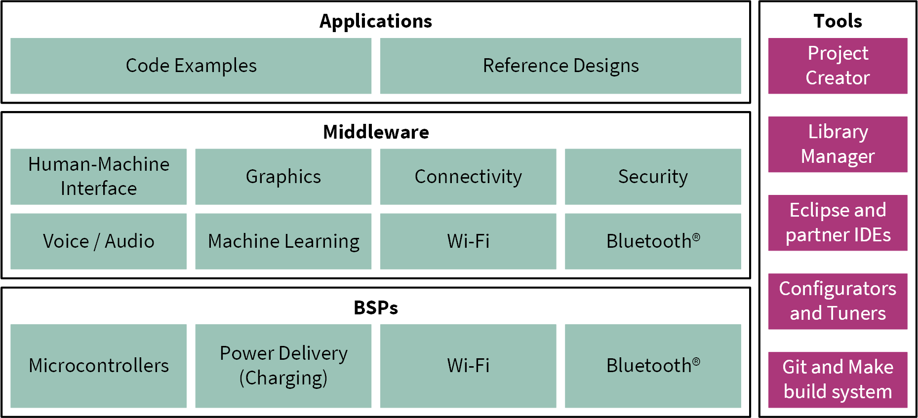
The ModusToolbox™ installer includes the design configurators and tools, and the build system infrastructure.
The build system infrastructure includes the new project creation wizard that can be run independent of the Eclipse IDE, the make infrastructure, and other tools.
All the ModusToolbox™ development flows depend on the provided low-level resources. These include:
Board support packages (BSP) – A BSP is the layer of firmware containing board-specific drivers and other functions. The board support package is a set of libraries that provide APIs to initialize the board and provide access to board level peripherals. It includes low-level resources such as Peripheral Driver Library (PDL) for TRAVEO™ T2G family MCU and has macros for board peripherals. It uses the HAL to configure the board. Custom BSPs can be created to enable support for end-application boards. See the “Board Support Packages” section in the ModusToolbox™ user guide for more information
Hardware Abstraction L ayer (HAL) – HAL provides a high-level interface to configure and use hardware blocks on MCUs. It is a generic interface that can be used across multiple product families. The focus on ease-of-use and portability means that the HAL does not expose all the low-level peripheral functionality. The HAL wraps the lower-level drivers (such as TRAVEO™ T2G family PDL) and provides a high-level interface to the MCU. The interface is abstracted to work on any MCU. This helps you write application firmware independent of the target MCU
The HAL can be combined with platform-specific libraries (such as TRAVEO™ T2G family PDL) within a single application. You can leverage the HAL's simpler and more generic interface for most of an application, even if one portion requires finer-grained control
The CYT4DN series does not support HAL for application code.
Peripheral Driver Library (PDL) – The PDL integrates the device header files, startup code, and peripheral drivers into a single package. The PDL supports the TRAVEO™ T2G family MCU device family. The drivers abstract the hardware functions into a set of easy-to-use APIs. These are fully documented in the PDL API Reference
The PDL reduces the need to understand register usage and bit structures, thus easing software development for the extensive set of peripherals in the TRAVEO™ T2G family MCU series. You configure the driver for your application, and then use API calls to initialize and use the peripheral
Extensive middleware libraries that provides specific capabilities to an application. All the middleware is delivered as libraries and via GitHub repositories
TRAVEO™ T2G family MCU software resources
The TRAVEO™ T2G family MCU software includes driver and middleware configurators to get you started developing firmware with TRAVEO™ T2G family MCU. It contains configurators, drivers, libraries, middleware, various utilities, Makefiles, and scripts. It also includes relevant drivers, middleware, and examples for use with industrial applications. You may use any or all tools in any environment you prefer.
Configurators
ModusToolbox™ software provides graphical applications called configurators that make it easier to configure a hardware block. For example, instead of having to search through all the documentation to configure a serial communication block as a UART with a desired configuration, open the appropriate configurator and set the baud rate, parity, and stop bits. After saving the hardware configuration, the tool generates the C code to initialize the hardware with the desired configuration.
Configurators are independent of each other, but they can be used together to provide flexible configuration options. They can be used standalone, in conjunction with other tools, or within a complete IDE. Configurators are used for:
Setting options and generating code to configure drivers
Setting up connections such as pins and clocks for a peripheral
Setting options and generating code to configure middleware
The following configurators are available for TRAVEO™ T2G family MCU applications:
Device Configurator: Sets up the system (platform) functions and the basic peripherals (for example, UART, Timer, and PWM)
QSPI Configurator: Configures the external memory and generates the required code
Smart I/O Configurator: Configures the smart I/O
Each of these configurators creates their own files (e.g., design.cyqspi for QSPI). The configurator files ( design.modus or design.cyqspi ) are usually provided with the BSP. The files are copied into the application when an application is created based on a BSP. Additionally, you can create custom device configurator files for an application and override the BSP-provided devices.
Library management for TRAVEO™ T2G family MCU
With the release of ModusToolbox™ v3.5, applications can optionally share board support packages (BSPs) and libraries. If needed, different applications can use different versions of the same BSP or library. The file types associated with libraries using this flow have a .mtb extension.
Section My first TRAVEO™ T2G family MCU design using Eclipse IDE for ModusToolbox™ software of this document describes creating a new application using this flow.
For more information on ModusToolbox™ flow, see the Library Manager user guide located at <install_dir> /ModusToolbox/tools_<version>/library-manager/docs/library-manager.pdf.
Software development for TRAVEO™ T2G family MCU
Significant source code and tools are provided to enable software development for TRAVEO™ T2G family MCUs. You use tools to specify how you want to configure the hardware, generate code for that purpose which you use in your firmware, and include various middleware libraries for additional functionality, like FreeRTOS. This source code makes it easier to develop the firmware for supported devices. It helps you quickly customize and build firmware without the need to understand the register set.
In the ModusToolbox™ environment, you use configurators to configure either the device or a middleware library, such as QSPI functionality.
The TRAVEO™ T2G family MCU Peripheral Driver Library code is delivered as the mtb-pdl-cat1 library. Middleware is delivered as separate libraries for each feature/function.
Whether you use the Eclipse IDE, a third-party IDE, or the command line, firmware developers who wish to work at the register level should see the driver source code from the PDL. The PDL includes all the device-specific header files and startup code you need for your project. It also serves as a reference for each driver. Because the PDL is provided as source code, you can see how it accesses the hardware at the register level.
Some devices do not support particular peripherals. The PDL is a superset of all the drivers for any supported device. This superset design means:
All API elements needed to initialize, configure, and use a peripheral are available
The PDL is useful across various TRAVEO™ T2G family MCU devices, regardless of available peripherals
The PDL includes error checking to ensure that the targeted peripheral is present on the selected device
This enables the code to maintain compatibility across products of the TRAVEO™ T2G family MCU family as long as the peripherals are available. A device header file specifies the peripherals that are available for a device. If you write the code that attempts to use an unsupported peripheral, you will get an error at compile time. Check the datasheet for the specific device to ensure that the peripheral is supported before writing the code to use that peripheral.
As shown in Figure 3 , with the Eclipse IDE for ModusToolbox™ software, you can:
Choose a board support package (BSP)
Create a new application based on a list of starter applications, filtered by kit
Add middleware
Develop your application firmware using the HAL or PDL for TRAVEO™ T2G family MCU
Note:
The CYT4DN series does not support HAL for application code.
Figure 3.
Eclipse IDE for ModusToolbox™ resources and middleware
Support for other IDEs
You can develop a firmware for TRAVEO™ T2G family MCUs using your favorite IDE such as IAR Embedded Workbench or Visual Studio Code .
ModusToolbox™ configurators are standalone tools that can be used to set up and configure TRAVEO™ T2G family MCU resources and other middleware components without using the Eclipse IDE. The device configurator and middleware configurator use the design.x files within the application workspace. You can then point to the generated source code and continue developing firmware in your IDE.
If there is a change in the device configuration, edit the design.x files using the configurators and regenerate the code for the target IDE. It is recommended that you generate resource configurations using the configuration tools provided with ModusToolbox™ software.
FreeRTOS support with ModusToolbox™
Adding native FreeRTOS support to a ModusToolbox™ application project is like adding any library or middleware. You can import the FreeRTOS middleware into your application by using the Library Manager. Select the application project and click the Library Manager link in the Quick Panel. Select freertos from the > TRAVEO™ T2G family MCU Middleware dialog, as shown in Figure 4 .
The .mtb file pointing to the FreeRTOS middleware is added to the application project. The middleware content is also downloaded and placed inside the corresponding folder called freertos. To continue working with FreeRTOS, follow the steps in the Quick Start section of FreeRTOS documentation .
Figure 4.
Import FreeRTOS middleware in ModusToolbox™ application
Programming/debugging
All TRAVEO™ T2G family MCU kits have a KitProg3 onboard programmer or debugger. It supports Cortex® Microcontroller Software Interface Standard-Debug Access Port (CMSIS-DAP). See the KitProg3 user guide for details.
The Eclipse IDE requires KitProg3 and uses the OpenOCD protocol for debugging TRAVEO™ T2G family MCU applications. Additionally, it supports GDB debugging using industry-standard probes like the Segger J-Link .
ModusToolbox™ includes the fw-loader command-line tool to update and switch the KitProg firmware from KitProg2 to KitProg3.
TRAVEO™ T2G family MCU development kits
Development kits
TRAVEO™ T2G Body High Evaluation Kit ( KIT_T2G-B-H_EVK )
TRAVEO™ T2G Body High Lite Kit ( KIT_T2G-B-H_LITE )
TRAVEO™ T2G Body Entry Lite Kit ( KIT_T2G-B-E_LITE )
TRAVEO™ T2G Cluster 2D 6M Lite Kit ( KIT_T2G_C-2D-6M_LITE )
For the complete list of kits for the TRAVEO™ T2G family MCU along with the shield modules, see the above microcontroller kits page.
Device features
TRAVEO™ T2G family MCU product lines have extensive feature sets. For more information, see References .
CYT4BF series
Figure 5.
CYT4BF MCU block diagram
CPU subsystem
Two 350 MHz Arm® Cortex®-M7 CPUs and one 100 MHz Arm® Cortex®-M0+ CPU
Inter-processor communication supported in hardware
Three DMA controllers
Integrated memories
Up to 8384 KB of code flash with an additional 256 KB work flash
Up to 1024 KB of SRAM selectable retention granularity
Cryptography engine
Supports Enhanced Secure Hardware Extension (eSHE) and Hardware Security Module (HSM)
Secure boot and authentication
AES: 128-bit blocks, 128-/192-/256-bit keys
3DES: 64-bit blocks, 64-bit key
Vector unit supporting asymmetric key cryptography such as Rivest-Shamir-Adleman (RSA) and Elliptic Curve (ECC)
SHA-1/2/3: SHA-512, SHA-256, SHA-160 with variable-length input data
CRC: supports CCITT CRC-16 and IEEE-802.3 CRC-32
True random number generator (TRNG) and pseudo random number generator (PRNG)
Galois/Counter Mode (GCM)
Safety for application
Memory protection unit (MPU)
Shared memory protection unit (SMPU)
Peripheral protection unit (PPU)
Watchdog timer (WDT)
Multi-counter watchdog timer (MCWDT)
Low-voltage detector (LVD)
Brown-out detection (BOD)
Over-voltage detection (OVD)
Clock supervisor (CSV)
Hardware error correction (SECDED ECC) on all safety-critical memories (SRAM, flash, TCM)
Low-power 2.7 V to 5.5 V operation
Low-power active, Sleep, Low-power Sleep, DeepSleep, and Hibernate modes for fine-grained power management
Configurable options for robust BOD
Wakeup
Up to two pins to wake from Hibernate mode
Up to 220 GPIO pins to wake from Sleep modes
Event Generator, SCB, Watchdog Timer, RTC alarms to wake from DeepSleep modes
Clocks
Internal main oscillator (IMO)
Internal low-speed oscillator (ILO)
External crystal oscillator (ECO)
Watch crystal oscillator (WCO)
Phase-locked loop (PLL)
Frequency-locked loop (FLL)
Communication interfaces
Up to 10 CAN FD channels
Up to 11 runtime-reconfigurable SCB channels, each configurable as I 2 C, SPI, or UART
Up to two 10/100/1000 Mbps Ethernet MAC interfaces conforming to IEEE-802.3az
External memory interface
One SPI (single, dual, quad, or octal) or HYPERBUS™ interface
On-the-fly encryption and decryption
Execute in place (XIP) from external memory
SDHC interface
One Secure Digital High Capacity (SDHC) interface supporting embedded MultiMediaCard (eMMC), Secure digital (SD), or SDIO (Secure digital input/output)
Data rates up to SD High-Speed 50 MHz, or eMMC 52 MHz DDR
Audio interface
Three Inter-IC Sound (I2S) interfaces (based on the NXP I2S bus specification) for connecting digital audio devices
I2S, left-justified, or Time Division Multiplexed (TDM) audio formats
Independent transmit or receive operation, each in master or slave mode
Timers
Up to 102 blocks of 16-bit and 16 blocks of 32-bit Timer/Counter Pulse-Width Modulator (TCPWM)
Up to 16 Event Generation (EVTGEN) timers supporting cyclic wakeup from DeepSleep
Real-time clock (RTC)
Year/Month/Date, Day-of-week, Hour:Minute:Second fields
12-hour and 24-hour formats
Automatic leap-year correction
I/O
Up to 240 programmable I/Os
Three I/O types: GPIO_STD/GPIO_ENH/HSIO_STD
Smart I/O
Up to five smart I/O blocks, which can perform Boolean operations on signals going to and from I/Os
Up to 36 I/Os (GPIO_STD) supported
Programmable analog
Three SAR A/D converters with up to 99 external channels (96 I/Os + 3 I/Os for motor control)
Each ADC supports 12-bit resolution and sampling rates of up to 1 Msps
Each ADC also supports six internal analog inputs
Each ADC supports addressing of external multiplexers
Each ADC has a sequencer supporting autonomous scanning of configured channels
Synchronized sampling of all ADCs for motor-sense applications
CYT2BL series
Figure 6.
CYT2BL MCU block diagram
CPU subsystem
160 MHz Arm® Cortex®-M4F CPU and one 100 MHz Arm® Cortex®-M0+ CPU
Inter-processor communication supported in hardware
Three DMA controllers
Integrated memories
Up to 4160 KB of code flash with an additional 128 KB work flash
Up to 512 KB of SRAM selectable retention granularity
Cryptography engine
Supports Enhanced Secure Hardware Extension (eSHE) and Hardware Security Module (HSM)
Secure boot and authentication
AES: 128-bit blocks, 128-/192-/256-bit keys
3DES: 64-bit blocks, 64-bit key
Vector unit supporting asymmetric key cryptography such as Rivest-Shamir-Adleman (RSA) and Elliptic Curve (ECC)
SHA-1/2/3: SHA-512, SHA-256, SHA-160 with variable-length input data
CRC: supports CCITT CRC-16 and IEEE-802.3 CRC-32
True random number generator (TRNG) and pseudo random number generator (PRNG)
Galois/Counter Mode (GCM)
Safety for application
Memory protection unit (MPU)
Shared memory protection unit (SMPU)
Peripheral protection unit (PPU)
Watchdog timer (WDT)
Multi-counter watchdog timer (MCWDT)
Low-voltage detector (LVD)
Brown-out detection (BOD)
Over-voltage detection (OVD)
Clock supervisor (CSV)
Hardware error correction (SECDED ECC) on all safety-critical memories (SRAM, flash)
Low-power 2.7 V to 5.5 V operation
Low-power active, Sleep, Low-power Sleep, DeepSleep, and Hibernate modes for fine-grained power management
Configurable options for robust BOD
Wakeup
Up to two pins to wake from Hibernate mode
Up to 152 GPIO pins to wake from Sleep modes
Event Generator, SCB, Watchdog Timer, RTC alarms to wake from DeepSleep modes
Clocks
Internal main oscillator (IMO)
Internal low-speed oscillator (ILO)
External crystal oscillator (ECO)
Watch crystal oscillator (WCO)
Phase-locked loop (PLL)
Frequency-locked loop (FLL)
Communication interfaces
Up to 8 CAN FD channels
Up to 8 runtime-reconfigurable SCB channels, each configurable as I 2 C, SPI, or UART
Up to 12 independent LIN channels
Up to four CXPI channels with data rate up to 20 kbps
Timers
Up to 75 blocks of 16-bit and 8 blocks of 32-bit Timer/Counter Pulse-Width Modulator (TCPWM)
Up to 11 Event Generation (EVTGEN) timers supporting cyclic wakeup from DeepSleep
Real-time clock (RTC)
Year/Month/Date, Day-of-week, Hour:Minute:Second fields
12-hour and 24-hour formats
Automatic leap-year correction
I/O
Up to 152 programmable I/Os
Two I/O types: GPIO_STD/GPIO_ENH
Smart I/O
Up to five smart I/O blocks, which can perform Boolean operations on signals going to and from I/Os
Up to 36 I/Os (GPIO_STD) supported
Programmable analog
Three SAR A/D converters with up to 67 external channels (64 I/Os + 3 I/Os for motor control)
Each ADC supports 12-bit resolution and sampling rates of up to 1 Msps
Each ADC also supports six internal analog inputs
Each ADC supports addressing of external multiplexers
Each ADC has a sequencer supporting autonomous scanning of configured channels
Synchronized sampling of all ADCs for motor-sense applications
CYT4DN series
Figure 7.
CYT4DN MCU block diagram
Graphics subsystem
Supports 2D and 2.5D (perspective warping, 3D effects) graphics rendering
40-bit for internal processing (RGBA 10-bit per color channel)
24-bit for interfaces (RGB 8-bit per color channel)
4096 KB of embedded video RAM memory (VRAM)
Up to two video output interfaces supporting two displays
One capture engine for video input processing for ITU 656 or parallel RGB/YUV or MIPI CSI-2 input
Display warping on-the-fly for HUD applications
Direct video feed through from capture to display interface with graphics overlay
Composition engine for scene composition from display layers
Display engine for video timing generation and display functions
Drawing engine for acceleration of vector graphics rendering
Command sequencer for setup and control of the rendering process
Supports graphics rendering without frame buffers (on-the-fly to both displays)
Dual-channel FPD-Link interface for up to Wide-HD resolution video output
JPEG decoder
Sound subsystem
Four time-division multiplexing (TDM) interfaces
Two pulse-code modulation-pulse width modulation (PCM-PWM) interfaces
Up to five sound generator (SG) interfaces
Two PCM audio stream mixers with five input streams
One audio digital-to-analog converter (DAC)
CPU subsystem
Two 320 MHz Arm® Cortex®-M7 CPUs and one 100 MHz Arm® Cortex®-M0+ CPU
Inter-processor communication supported in hardware
Three DMA controllers
Integrated memories
Up to 6336 KB of code flash with an additional 128 KB work flash
Up to 640 KB of SRAM selectable retention granularity
Cryptography engine
Supports Enhanced Secure Hardware Extension (eSHE) and Hardware Security Module (HSM)
Secure boot and authentication
AES: 128-bit blocks, 128-/192-/256-bit keys
3DES: 64-bit blocks, 64-bit key
Vector unit supporting asymmetric key cryptography such as Rivest-Shamir-Adleman (RSA) and Elliptic Curve (ECC)
SHA-1/2/3: SHA-512, SHA-256, SHA-160 with variable-length input data
CRC: Supports CCITT CRC-16 and IEEE-802.3 CRC-32
True random number generator (TRNG) and pseudo random number generator (PRNG)
Galois/Counter Mode (GCM)
Safety for application
Memory protection unit (MPU)
Shared memory protection unit (SMPU)
Peripheral protection unit (PPU)
Watchdog timer (WDT)
Multi-counter watchdog timer (MCWDT)
Low-voltage detector (LVD)
Brown-out detection (BOD)
Over-voltage detection (OVD)
Clock supervisor (CSV)
Hardware error correction (SECDED ECC) on all safety-critical memories (SRAM, flash, TCM)
Low-power 2.7 V to 5.5 V operation
Low-power active, Sleep, Low-power Sleep, DeepSleep, and Hibernate modes for fine-grained power management
Configurable options for robust BOD
Wakeup
Up to 10 pins to wake from Hibernate mode
Up to 81 GPIO pins to wake from Sleep modes
Event generator, SCB, watchdog timer, and RTC alarms to wake from DeepSleep modes
Clocks
Internal main oscillator (IMO)
Internal low-speed oscillator (ILO)
External crystal oscillator (ECO)
Watch crystal oscillator (WCO)
Phase-locked loop (PLL)
Frequency-locked loop (FLL)
Low-power external crystal oscillator (LPECO)
Communication interfaces
Up to 4 CAN FD channels
Up to 12 runtime-reconfigurable SCB channels, each configurable as I 2 C, SPI, or UART
Up to 2 independent LIN channels
Up to 2 CXPI channels with data rate up to 20 kbps
Timers
Up to 50 blocks of 16-bit and 32 blocks of 32-bit Timer/Counter Pulse-Width Modulator (TCPWM)
Up to 12 blocks of 16-bit counters optimized for motor-control operations (equivalent to 6 stepper motor-control (SMC) channels with ZPD and slew rate control capability)
Up to 16 Event Generation (EVTGEN) timers supporting cyclic wakeup from DeepSleep
Real-time clock (RTC)
Year/Month/Date, Day-of-week, Hour:Minute:Second fields
12-hour and 24-hour formats
Automatic leap-year correction
I/O
Up to 168 programmable I/Os
Seven I/O types: GPIO_STD/GPIO_ENH/GPIO_SMC/HSIO_STD/HSIO_STDLN/HSIO_ENH/HSIO_ENH_PDIFF
Smart I/O
One smart I/O blocks, which can perform Boolean operations on signals going to and from I/Os
Up to 8 I/Os (GPIO_STD) supported
Programmable analog
One SAR A/D converter with up to 48 external channels
Each ADC supports 12-bit resolution and sampling rates of up to 1 Msps
Each ADC also supports six internal analog inputs
Each ADC supports addressing of external multiplexers
Each ADC has a sequencer supporting autonomous scanning of configured channels
My first TRAVEO™ T2G family MCU design using Eclipse IDE for ModusToolbox™ software
This section provides the following:
Demonstrates how to build a simple design based on TRAVEO™ T2G family MCU and program it on to the development kit
Provides detailed steps that make it easy to learn TRAVEO™ T2G family MCU design techniques and how to use the Eclipse IDE for ModusToolbox™ software
Prerequisites
Before you get started, ensure that you have the appropriate development kit for your TRAVEO™ T2G family MCU product line, and have installed the required software. You also need Internet access to the GitHub repositories during project creation.
Hardware
The design is developed for TRAVEO™ T2G family evaluation kit . However, you can build the projects for other development kits. See the Using these instructions section.
Software
ModusToolbox™ 3.5 or above
After installing the software, see the ModusToolbox™ user guide to get an overview of the software.
For a list of known issues, see mt_release_notes.pdf included with the ModusToolbox™ installation. The default location of this file is <user-home>/ModusToolbox/docs_3.5.
Using these instructions
These instructions are grouped into several sections. Each section is devoted to a phase of the application development workflow. The major sections are:
Part 1: Create a new application
Part 2: View and modify the design
Part 3: Write firmware
Part 4: Build the application
Part 5: Program the device
Part 6: Test your design
This design is developed for the TRAVEO™ T2G family MCU Evaluation Kit . You can use other supported kits to test this example by selecting the appropriate kit while creating the application.
About the design
This design uses the TRAVEO™ T2G family MCU to execute two tasks: UART communication and LED control.
After device reset, this code example uses the UART to print a “Hello World” message to the serial port stream, and starts blinking the user LED on the kit. When you press the Enter key on the serial console, the blinking is paused or resumed.
Part 1: Create a new application
This section takes you on a step-by-step guided tour of the new application process. It uses the ‘Empty App’ starter application and guides you through the design development stages, and programming.
If you are familiar with developing projects with ModusToolbox™, you can use the ‘Hello World’ starter application directly. It is a complete design, with all the firmware written for the supported kits. You can walk through the instructions and observe how the steps are implemented in the code example.
If you start from scratch and follow all the instructions in this application note, you can use the code example as a reference while following the instructions.
Launch Eclipse IDE for ModusToolbox™ to get started. Note that Eclipse IDE for ModusToolbox™ software needs access to the internet to successfully clone the starter application onto your machine. The following shows the CYT4BF project as an example.
- Select a new workspace
At launch, Eclipse IDE for ModusToolbox™ presents a dialog to choose a directory for use as the workspace directory. The workspace directory is used to store workspace preferences and development artifacts. You can choose an existing empty directory by clicking the Browse button, as Figure 8 shows. Alternatively, you can type in a directory name to be used as the workspace directory along with the complete path, and the Eclipse IDE will create the directory for you.
Figure 8.
Select a directory as the workspace
- Create a new ModusToolbox™ application
Click New Application in the Start group of the Quick Panel
Alternatively, you can choose
ModusToolbox™ Application , as shown in Figure 9
The Eclipse IDE for ModusToolbox™ Application window appears.
Figure 9. Create a new ModusToolbox™ application
- Select a target TRAVEO™ T2G family MCU evaluation kit
ModusToolbox™ speeds up the development process by providing BSPs that set various workspace/project options for the specified development kit in the new application dialog.
In the Choose Board Support Package (BSP) dialog, choose the Kit Name that you have. The steps that follow use KIT_T2G-B-H_EVK . See Figure 10 for help with this step
Click Next
Figure 10.
Choose the target hardware
In the Starter Application dialog, select starter application, as Figure 11 shows
In the Name field, type in a name for the application, such as Hello_World . You can choose to leave the default name if you prefer
Click Create to create the application, as shown in Figure 11 . Wait for the Project Creator to automatically close once the project is successfully created
Figure 11.
Choose the starter application
You have successfully created a new ModusToolbox™ application for a TRAVEO™ T2G family MCU.
The BSP uses CYT4BFBCH as the default device that is mounted on the TRAVEO™ T2G family MCU evaluation kit.
If you are using custom hardware based on a TRAVEO™ T2G family MCU, or a different TRAVEO™ T2G family MCU part number, see the “Creating your Own BSP” section in the ModusToolbox™ user guide .
Part 2: View and modify the design
Figure 12 shows the ModusToolbox™ Project Explorer interface displaying the structure of the application project.
TRAVEO™ T2G family CYT4BF MCU consist of three cores: one CM0+ core and two CM7 cores. This application note shows an example code for the firmware development using ModusToolbox™ software.
A project folder consists of various subfolders – each denoting a specific aspect of the project.
An application project contains a Makefile which is typically at the root folder. It has instructions on how to recreate the project. This file also contains the set of directives that the make tool uses to compile and link the application project. There can be more than one project in an application, and each dependent project usually resides within its own folder within the application folder and contains its own Makefile
The bsps folder contains all the configuration files that are generated by the device and peripheral configurators, and are included in the GeneratedSource folder of the BSP. These files are prefixed with cycfg_ . These files contain the design configuration as defined by the BSP. You can view and modify the design configuration by clicking the Device Configurator link in the Quick Panel. However, note that if you upgrade the BSP library to a newer version, the manual edits done to the design.x files are lost. You can also create custom Device Configurator files for an application and override the ones provided by the BSP. See the “Modifying the BSP configuration for a single application” section in the ModusToolbox™ user guide for more details. The BSP folder also contains the linker scripts and the startup code for the TRAVEO™ T2G family MCU device used on the board
The build folder contains all the artifacts resulting from the make build of the project. The output files are organized by target BSPs
Figure 12.
Project explorer view
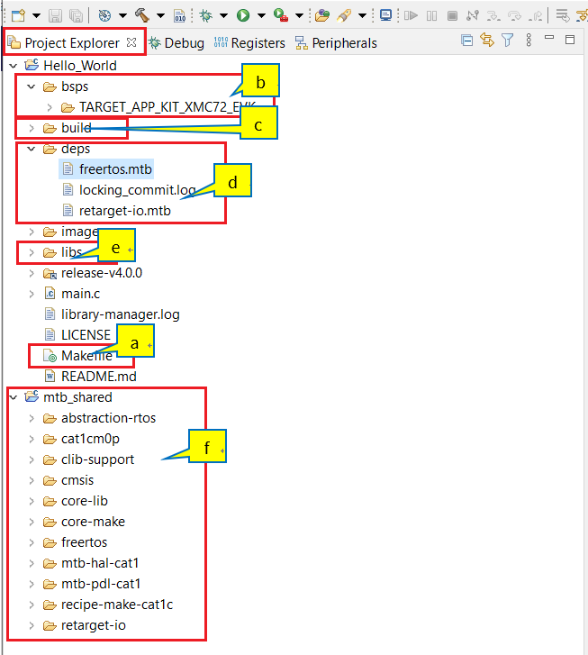
The deps folder contains .mtb files, which provide the location from which ModusToolbox™ software pulls the BSP/library that is directly referenced by the application. These files typically contain the GitHub location of the entire library. The .mtb files also contains a git commit hash or tag that tells which version of the library is to be fetched and a path as to where the library should be stored
For example, retarget-io.mtb points to https://github.com/infineon/retarget-io#latest-v1.X#$$ASSET_REPO$$/retarget-io/latest-v1.X
The libs folder also contains .mtb files; these point to libraries that are included indirectly as a dependency of a BSP or another library. For each indirect dependency, the Library Manager places an .mtb file in this folder. These files have been populated based on the targets available in the deps folder
For example, using the BSP lib file, TARGET_KIT_T2G-B-H_EVK.mtb populates the libs folder with the following .mtb files: core-lib.mtb , core-make.mtb , mtb-hal-cat1.mtb , mtb-pdl-cat1.mtb , recipe-make-cat1 c .mtb
The libs folder contains the mtb.mk file, which stores the relative paths of the all the libraries required by the application. The build system uses this file to find all the libraries required by the application
By default, when creating a new application or adding a BSP/library to an existing application and specifying it as ‘shared’, all BSPs/libraries are placed in an mtb_shared directory adjacent to the application directories
The mtb_shared folder is shared between different applications that use the same versions of the BSP/library
Of interest are the configuration files that are in the COMPONENT_BSP_x folder. Click on the Device Configurator link in the Quick Panel . Figure 13 shows the resulting window called the Device Configurator window. You can also double-click open the other design.x files to open them in their respective configurators or click the corresponding links in the Quick Panel .
Figure 13. design.modus overview
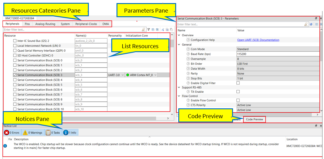
The Device Configurator window provides a Resources Categories pane. Here you can choose between different resources available in the device such as peripherals, pins, and clocks from the List of Resources .
You can choose how a resource behaves by choosing a Personality for the resource. For example, a Serial Communication Block (SCB) resource can have EZI2C , I2C , SPI , or UART personalities. The Alias is your name for the resource, which is used in firmware development. One or more aliases can be specified by using a comma to separate them (with no spaces).
The Parameters pane is where you enter the configuration parameters for each enabled resource and the selected personality. The Code Preview pane shows the configuration code generated per the configuration parameters selected. This code is populated in the cycfg_ files in the GeneratedSource folder. Any errors, warnings, and information messages arising out of the configuration are displayed in the Notices pane.
The application project contains relevant files that help you create an application for the CM7 CPU (main.c) .
At this point in the development process, we are ready to add the required middleware to the design. The only middleware required for the ‘Hello World’ application is the retarget-io library.
Figure 14.
Add the retarget-io middleware
- Add retarget-io middleware
In this step, you will add the retarget-io middleware to redirect standard input and output streams to the UART configured by the BSP. The initialization of the middleware will be done in the main.c code
In the Quick Panel , click on the Library Manager link
In the Library Manager window, click on Add Library
Under Peripheral , select and enable retarget-io , and click OK
Click Update
The necessary files to use the retarget-io middleware are added in the mtb_shared/retarget_io folder; the .mtb file is also added to the deps folder (see Figure 14 )
- Configuration of UART, timer peripherals, pins, and system clocks
The configuration of the debug UART peripheral, timer peripheral, pins, and system clocks can be done directly in the code using the function APIs provided by the BSP and HAL. See Part 3: Write firmware .
Part 3: Write firmware
At this point in the development process, you have created an application, with the assistance of an application template and modified it to add the retarget-io middleware. In this part, you write the firmware that implements the design functionality.
If you are working from scratch using the empty TRAVEO™ T2G family starter application, you can copy the respective source code to the main.c of the application project from the code snippet provided in this section. If you are using the Hello World code example, all the required files are already in the application.
Firmware flow
We now examine the code in the main.c file of the application. Figure 15 shows the firmware flowchart.
After reset, this code example initializes and configures the system clocks, pins, clock to peripheral connections, and other platform resources.
After reset, the clocks and system resources are initialized by the BSP initialization function. The retarget-io middleware is configured to use the debug UART, and the user LED is initialized. The debug UART prints a “Hello World!” message on the terminal emulator – the onboard KitProg3 acts the USB-to-UART bridge to create the virtual COM port. A timer object is configured to generate an interrupt every 1000 milliseconds. At each timer interrupt, CPU toggles the LED state on the kit.
The firmware is designed to accept ‘Enter’ key as an input; on every press of the Enter key, the firmware starts or stops the blinking of the LED.
The application code uses BSP/HAL/middleware functions to execute the intended functionality.
Figure 15. Firmware flowchart
This completes the summary of how the firmware works in the code example. See the source files for more information.
Function | Description |
|---|---|
cybsp_init() | This BSP function sets up the HAL hardware manager and initializes all the system resources of the device including but not limited to the system clocks and power regulators |
cy_retarget_io_init() | This function from the retarget-io middleware uses the aliases set up for debug UART pins to configure the debug UART with a standard baud rate of 115200 and redirects the input/output stream to the debug UART |
cyhal_gpio_init() | This function from the GPIO HAL initializes the physical pin to drive the LED. The LED used is derived from the BSP definition |
timer_init() | This function wraps a set of timer HAL function calls to instantiate and configure a timer. It also sets up a callback for the timer interrupt |
Copy the following code snippet to the main.c of your application project.
Example code for the ‘Hello World’ application
#include "cyhal.h"
#include "cybsp.h"
#include "cy_retarget_io.h"


/*******************************************************************************
* Macros
*******************************************************************************/

/* LED blink timer clock value in Hz  */
#define LED_BLINK_TIMER_CLOCK_HZ          (10000)

/* LED blink timer period value */
#define LED_BLINK_TIMER_PERIOD            (9999)


/*******************************************************************************
* Function Prototypes
*******************************************************************************/
void timer_init(void);
static void isr_timer(void *callback_arg, cyhal_timer_event_t event);


/*******************************************************************************
* Global Variables
*******************************************************************************/
bool timer_interrupt_flag = false;
bool led_blink_active_flag = true;

/* Variable for storing character read from terminal */
uint8_t uart_read_value;

/* Timer object used for blinking the LED */
cyhal_timer_t led_blink_timer;


/*******************************************************************************
* Function Name: main
********************************************************************************
* Summary:
* This is the main function. It sets up a timer to trigger a
* periodic interrupt. The main while loop checks for the status of a flag set
* by the interrupt and toggles an LED at 1Hz to create an LED blinky. The
* while loop also checks whether the 'Enter' key was pressed and
* stops/restarts LED blinking.
*
* Parameters:
*  none
*
* Return:
*  int
*
*******************************************************************************/
int main(void)
{
    cy_rslt_t result;

    /* Initialize the device and board peripherals */
    result = cybsp_init();

    /* Board init failed. Stop program execution */
    if (result != CY_RSLT_SUCCESS)
    {
        CY_ASSERT(0);
    }

    /* Enable global interrupts */
    __enable_irq();

    /* Initialize retarget-io to use the debug UART port */
    result = cy_retarget_io_init(CYBSP_DEBUG_UART_TX, CYBSP_DEBUG_UART_RX,
                                 CY_RETARGET_IO_BAUDRATE);

    /* retarget-io init failed. Stop program execution */
    if (result != CY_RSLT_SUCCESS)
    {
        CY_ASSERT(0);
    }

    /* Initialize the User LED */
    result = cyhal_gpio_init(CYBSP_USER_LED, CYHAL_GPIO_DIR_OUTPUT,
                             CYHAL_GPIO_DRIVE_STRONG, CYBSP_LED_STATE_OFF);

    /* GPIO init failed. Stop program execution */
    if (result != CY_RSLT_SUCCESS)
    {
        CY_ASSERT(0);
    }

    /* \x1b[2J\x1b[;H - ANSI ESC sequence for clear screen */
    printf("\x1b[2J\x1b[;H");

    printf("****************** "
           "HAL: Hello World! Example "
           "****************** \r\n\n");

    printf("Hello World!!!\r\n\n");

    printf("For more projects, "
           "visit our code examples repositories:\r\n\n");

    printf("https://github.com/Infineon/"
           "Code-Examples-for-ModusToolbox-Software\r\n\n");

    /* Initialize timer to toggle the LED */
    timer_init();

    printf("Press 'Enter' key to pause or "
           "resume blinking the user LED \r\n\r\n");

    for (;;)
    {
        /* Check if 'Enter' key was pressed */
        if (cyhal_uart_getc(&cy_retarget_io_uart_obj, &uart_read_value, 1)
             == CY_RSLT_SUCCESS)
        {
            if (uart_read_value == '\r')
            {
                /* Pause LED blinking by stopping the timer */
                if (led_blink_active_flag)
                {
                    cyhal_timer_stop(&led_blink_timer);

                    printf("LED blinking paused \r\n");
                }
                else /* Resume LED blinking by starting the timer */
                {
                    cyhal_timer_start(&led_blink_timer);

                    printf("LED blinking resumed\r\n");
                }

                /* Move cursor to previous line */
                printf("\x1b[1F");

                led_blink_active_flag ^= 1;
            }
        }

        /* Check if timer elapsed (interrupt fired) and toggle the LED */
        if (timer_interrupt_flag)
        {
            /* Clear the flag */
            timer_interrupt_flag = false;

            /* Invert the USER LED state */
            cyhal_gpio_toggle(CYBSP_USER_LED);
        }
    }
}


/*******************************************************************************
* Function Name: timer_init
********************************************************************************
* Summary:
* This function creates and configures a Timer object. The timer ticks
* continuously and produces a periodic interrupt on every terminal count
* event. The period is defined by the 'period' and 'compare_value' of the
* timer configuration structure 'led_blink_timer_cfg'. Without any changes,
* this application is designed to produce an interrupt every 1 second.
*
* Parameters:
*  none
*
*******************************************************************************/
 void timer_init(void)
 {
    cy_rslt_t result;

    const cyhal_timer_cfg_t led_blink_timer_cfg =
    {
        .compare_value = 0,                 /* Timer compare value, not used */
        .period = LED_BLINK_TIMER_PERIOD,   /* Defines the timer period */
        .direction = CYHAL_TIMER_DIR_UP,    /* Timer counts up */
        .is_compare = false,                /* Don't use compare mode */
        .is_continuous = true,              /* Run timer indefinitely */
        .value = 0                          /* Initial value of counter */
    };

    /* Initialize the timer object. Does not use input pin ('pin' is NC) and
     * does not use a pre-configured clock source ('clk' is NULL). */
    result = cyhal_timer_init(&led_blink_timer, NC, NULL);

    /* timer init failed. Stop program execution */
    if (result != CY_RSLT_SUCCESS)
    {
        CY_ASSERT(0);
    }

    /* Configure timer period and operation mode such as count direction,
       duration */
    cyhal_timer_configure(&led_blink_timer, &led_blink_timer_cfg);

    /* Set the frequency of timer's clock source */
    cyhal_timer_set_frequency(&led_blink_timer, LED_BLINK_TIMER_CLOCK_HZ);

    /* Assign the ISR to execute on timer interrupt */
    cyhal_timer_register_callback(&led_blink_timer, isr_timer, NULL);

    /* Set the event on which timer interrupt occurs and enable it */
    cyhal_timer_enable_event(&led_blink_timer, CYHAL_TIMER_IRQ_TERMINAL_COUNT,
                              7, true);

    /* Start the timer with the configured settings */
    cyhal_timer_start(&led_blink_timer);
 }


/*******************************************************************************
* Function Name: isr_timer
********************************************************************************
* Summary:
* This is the interrupt handler function for the timer interrupt.
*
* Parameters:
*    callback_arg    Arguments passed to the interrupt callback
*    event            Timer/counter interrupt triggers
*
*******************************************************************************/
static void isr_timer(void *callback_arg, cyhal_timer_event_t event)
{
    (void) callback_arg;
    (void) event;

    /* Set the interrupt flag and process it from the main while(1) loop */
    timer_interrupt_flag = true;
}
Part 4: Build the application
This section shows how to build the application.
- Build the application
Select the application project in the Project Explorer window and click on the shortcut under the group in the Quick Panel. It selects the Debug build configuration and compiles/links all projects that constitute the application
The Console view lists the results of the build operation (see Figure 16 )
Figure 16. Build the application
If you encounter errors, revisit prior steps to ensure that you accomplished all the required tasks.
You can also use the command-line interface (CLI) to build the application. See the “Using the command-line” section in the ModusToolbox™ user guide . This document is located in the /ide_<version>/docs/ folder in the ModusToolbox™ installation.
Part 5: Program the device
This section shows how to program the TRAVEO™ T2G family MCU device.
ModusToolbox™ software uses the OpenOCD protocol to program and debug applications on TRAVEO™ T2G family MCU devices. For ModusToolbox™ software to identify the device on the kit, the kit must be running KitProg3. See Programming/debugging for details.
If you are using a development kit with a built-in programmer, connect the board to your computer using the USB cable.
If you are developing on your own hardware, you may need a hardware programmer/debugger; for example, a CY8CKIT-005 MiniProg4 .
- Program the application
Connect to the board and perform the following step
Select the application project and click on the ) shortcut under the Launches group in the Quick Panel, as Figure 17 shows. The IDE will select and run the appropriate run configuration. Note that this step will also perform a build if any files have been modified since the last build
Figure 17.
+Programming an application to a deviceConsole – programming results
The Console view lists the results of the programming operation, as Figure 18 shows.
Figure 18.
Console – programming results
Part 6: Test your design
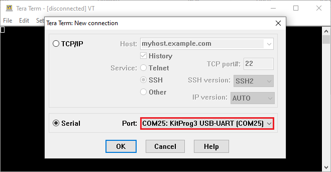
This application note uses Tera Term as the UART terminal emulator to view the results. You can use any terminal of your choice to view the output. Follow these steps to observe the output of your design:
- Select the serial port
Launch Tera Term and select the USB-UART COM port as shown in Figure 19 . Note that your COM port number may be different
Figure 19.
Selecting the KitProg3 COM port in Tera Term
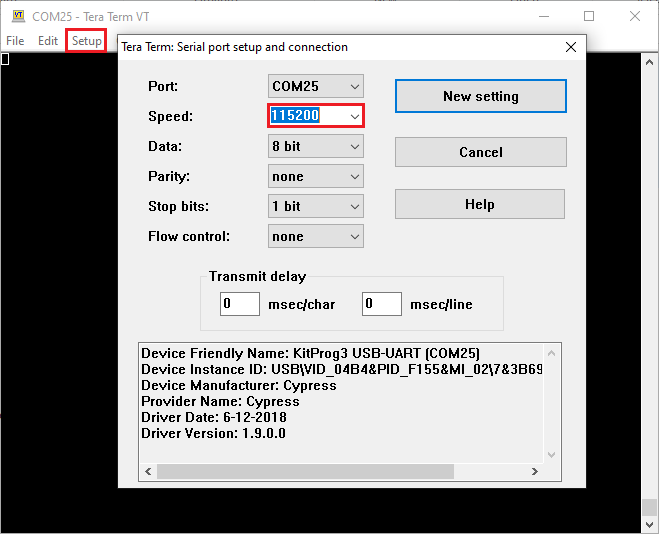
- Set the baud rate
Set the baud rate to 115200 under as shown in Figure 20
Figure 20. Configuring the baud rate in Tera Term
- Reset the device
Press the reset switch ( SW1 ) on the kit. A message appears on the terminal as shown in Figure 21 . The user LED on the kit starts blinking
Figure 21. Printed UART message
- Pause/resume LED blinking functionality
Press the Enter key to pause/resume blinking the LED. When the LED blinking is paused, a corresponding message is displayed on the terminal as shown in Figure 22
Figure 22. Printed UART message
How to use the Qt Design Studio
KIT_T2G-C-2D-6M_LITE kit has a demonstration code example ModusToolbox™ and Qt Design Studio working together to output image. To use these graphics code examples, some configuration is required in advance.
Follow the instructions on how to set up Qt Design Studio and use it with the KIT_T2G-C-2D-6M_LITE kit. For more details, see the Steps to use the Qt Design Studio using the ModusToolbox™ .
To procure the license, go to Qt + Infineon
To download Qt software, go to Login
Install Qt Design Studio
To install, go to TRAVEO™ T2G Virtual Display Tool
Configure the Windows environment variable on your PC
The above procedure should be performed before creating the graphics.
Summary
This application note explores the TRAVEO™ T2G family MCU device architecture and the associated development tools. The TRAVEO™ T2G family MCU is a truly programmable embedded system-on-chip with configurable analog and digital peripheral functions, memory, and a triple-CPU system on a single chip. The integrated features and low-power modes make TRAVEO™ T2G family MCU an ideal choice for BCM, gateway, instrument cluster, and other automotive body control applications.
References
TRAVEO™ T2G webpage
Application notes
Device datasheets
CYT2BL architecture/registers reference manual for body controller entry family
- TRAVEO™ T2G automotive body controller entry family architecture reference manual
- TRAVEO™ T2G automotive body controller entry registers reference manual
CYT4BF architecture/registers reference manual for body controller high family
CYT4DN architecture/registers reference manual for body controller high family
Customer training workshop (CTW)
- Steps to use the Qt Design Studio using the ModusToolbox™
For more TRAVEO™ T2G documents, contact Technical Support .
Glossary
This section lists the most commonly used terms that you might encounter while working with TRAVEO™ T2G family of devices.
Board support package (BSP) : A BSP is the layer of firmware containing board-specific drivers and other functions. The board support package is a set of libraries that provide firmware APIs to initialize the board and provide access to board level peripherals
Hardware Abstraction Layer (HAL) : The HAL wraps the lower-level drivers and provides a high-level interface to the MCU. The interface is abstracted to work on any MCU
KitProg : Onboard programmer/debugger with USB-I 2 C and USB-UART bridge functionality. KitProg is integrated onto most TRAVEO™ T2G development kits
MiniProg3 / MiniProg4 : Programming hardware for development that is used to program TRAVEO™ T2G devices on your custom board or TRAVEO™ T2G development kits that do not support a built-in programmer
Personality : Expresses the configurability of a resource for a functionality. For example, the SCB resource can be configured to be an UART, SPI, or I 2 C personalities
Middleware : Middleware is a set of firmware modules that provide specific capabilities to an application. Some middleware may provide network protocols (e.g., MQTT), and some may provide high-level software interfaces to device features (e.g., USB, audio)
Peripheral Driver L ibrary (PDL): Simplifies software development for the TRAVEO™ T2G MCU architecture. The PDL reduces the need to understand register usage and bit structures, thus easing software development for the extensive set of peripherals available
Revision history
Document revision | Date | Description of changes |
|---|---|---|
** | 2022-09-14 | Initial release |
*A | 2022-11-14 | Added 4.7.1 section |
*B | 2023-04-06 | Added KIT_T2G-B-H_LITE Added Enable support for additional code example section |
*C | 2023-10-16 | Added CYT2BL series related information in all instances across the document Added KIT_T2G-B-E_LITE |
*D | 2023-11-27 | Web release |
*E | 2024-11-25 | Added CYT4DN series related information in all instances across the document Added KIT_T2G_C_2D-6M_LITE |
*F | 2025-09-01 | Updated how to set Manifest-DB and supported version for ModusToolbox™ from 3.2 to 3.5 |