AN229058 Secured firmware over-the-air (FOTA) update in TRAVEO™ T2G MCU
About this document
Scope and purpose
AN229058 explains the different steps involved in developing a “secure” and reliable firmware over-the-air (FOTA) update in TRAVEO™ T2G MCU. Note that this document does not explain the setting up of a wireless interface to perform an update over the air, rather explains how a logical flash bank in the TRAVEO™ T2G MCU can be updated with the new image and how reliably (using TRAVEO™ T2G MCU’s “Secure Boot” mechanisms) the boot code can jump to the new image if successfully authenticated.
Intended audience
This document is intended for anyone using firmware over-the-air update for TRAVEO™ T2G MCU.
Introduction
This application note describes how FOTA (firmware over-the-air) updates can be securely performed in TRAVEO™ T2G MCUs. The series includes Arm® Cortex®-M CPUs with enhanced “secure” hardware extension (eSHE) or hardware security module (HSM), CAN FD, memory, and analog and digital peripheral functions in a single chip.
In the automotive embedded systems, FOTA update is a remote software management technology that helps to perform wireless firmware upgrade on the device. Upgrading the device firmware once it is on the field might be essential especially when the system demands critical bug fixes, addition of a new feature, removal of an existing feature, and so on.
The complete implementation of FOTA is highly dependent on the device architecture (here TRAVEO™ T2G device). TRAVEO™ T2G MCU’s internal code flash architecture supports dual bank modes, which are mainly targeted for FOTA applications. This architecture ensures that the existing application is uninterrupted while a FOTA update happens and the new application is launched securely. The FOTA update should also mandate a roll-back mechanism to the old firmware if the new update is corrupted or interrupted for any reason.
This application note mainly focuses on the development of a dual bank manager code, which helps you to check the validity of the new application image (using cryptographic authentication functions) and then ensure that the validated image is launched by correctly modifying the flash bank and remap registers.
Note that this is an advanced application note. See the following application notes before proceeding:
Introduction to FOTA
Figure 1 illustrates a typical example for a FOTA system in the automotive network.
Figure 1.
Typical FOTA system
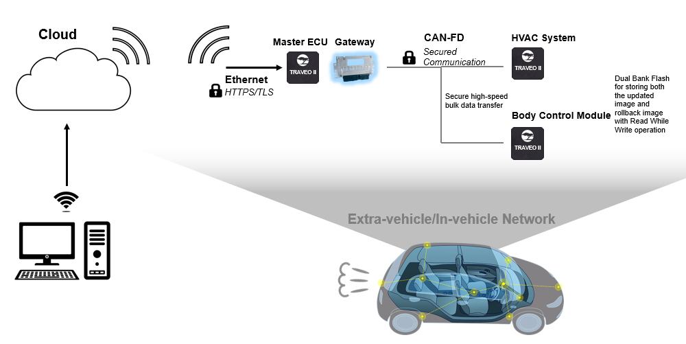
The master electronic control unit (ECU) communicates with the cloud to receive the new image. It can then implement a gateway (based on CAN-FD for example) to update the images of the other TRAVEO™ T2G subsystems like the HVAC system and the body control module. This communication can also be made secured using crypto encryption and decryption and by using protection units (for example, Software Protection Units (SWPUs)), which allows only those ECUs with privileges for flash writes to perform flash upgrades.
TRAVEO™ T2G device supports true FOTA. This means that the:
Update of the software image happens in the background. There is no interruption of application service.
Update can be rolled back if there is a failure or as needed by the application.
This True FOTA is possible with TRAVEO™ T2G device as it supports:
Dual bank flash
Read-while-write memory, allowing execution of software (read) while programming (write)
Multiple levels of security and “Secure Boot”
Challenges with conventional FOTA (without “Secure Boot”)
Figure 2 shows the code flash memory mapping for an 8-MB memory in TRAVEO™ T2G device.
Figure 2.
Code flash memory mapping for 8-MB code flash
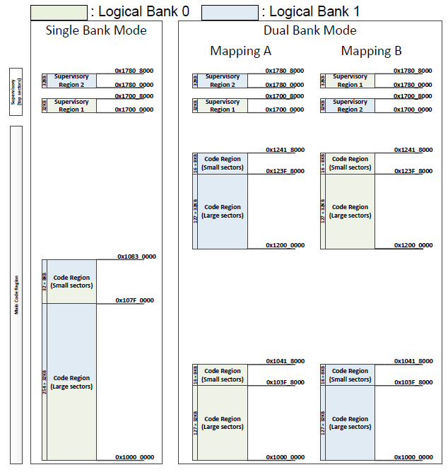
FOTA architecture uses dual bank mode. If there is a power failure or any other hardware issues during the FOTA upgrade, TRAVEO™ T2G device might enter a corrupted state. For instance, if there is a FOTA request while the application is executing code in Mapping B, the new image must be written to logical flash bank 0. Now, if there is a power failure or corruption while the first few sectors were getting updated, TRAVEO™ T2G device could enter into a lock-up or corrupted state after the next reset because flash boot always executes in single bank mode and by default jumps to the address specified by the address of first user application object (that has the vector table, which is now corrupted) in TOC2 (see section TOC2 details ). Implementing a “Secure Boot” mechanism based on the techniques discussed in this application note will help mitigate this issue.
Bank switching mechanism in TRAVEO™ T2G MCU
In TRAVEO™ T2G family MCUs, OTA functionality is handled by two separate bits in the FLASHC_FLASH_CTL register. The MAIN_BANK_MODE bit is used to configure flash bank mode between single and dual banks. MAIN_MAP bit is used to configure flash region between mapping A and mapping B. Both these bits are cleared by reset. ROM boot and Flash boot do not touch these configurations. In other words, TRAVEO™ T2G family MCU always boots up in single bank mode before the Arm® Cortex®-M0+ program starts. The application needs to configure dual bank and remap function as required.
The MAIN_BANK_MODE bit is part of the FLASHC_FLASH_CTL register. Dual bank mode is enabled if FLASHC_FLASH_CTL.MAIN_BANK_MODE = 1.
The MAIN_MAP bit is also part of the FLASHC_FLASH_CTL register. Mapping A is used if this bit is “0” and mapping B is used if this bit is “1”.
For more details on FLASHC_FLASH_CTL register, see the registers technical reference manual (TRM).
Note that the Dual Bank Manager software which is intensively discussed in the application note configures the bank mode and mapping registers based on certain criteria. This dual bank manager software is programmed to the user SFlash memory and is triggered by CM0+ after the normal Flash Boot operations.
For more details on Bank switching, see AN220242 - Flash accessing procedure for TRAVEO™ T2G f amily.
Also, note that the bits MAIN_BANK_MODE and MAIN_MAP must not be modified by any code executed from the code flash or SFlash as this involves sudden changes in the flash geometry. In the implementation described in this application note, dual bank manager copies a code from SFlash to SRAM, and this code which is executed out of SRAM configures these bits.
Introduction to “Secure Boot”
This section introduces TRAVEO™ T2G MCU’s boot sequence. For a detailed description of TRAVEO™ T2G MCU’s security features, different lifecycle stages, and implementation of “Secure Boot” sequence, see AN228680 - Secure system configuration in TRAVEO™ T2G family.
TRAVEO™ T2G MCU’s boot sequence ( Figure 3 ) is based on the ROM boot code and flash boot code implemented for different lifecycle stages. Figure 3 shows how the CM0+ operation starts from reset. After reset, CM0+ starts executing from ROM boot. ROM boot validates SFlash. After validation of SFlash is complete, execution jumps to flash boot and configures the DAP as needed by the protection state. Notice the color coding that depicts the memory type where data and code reside.
Figure 3.
TRAVEO™ T2G boot sequence
The flash boot then validates the first application listed in TOC2 and jumps to its entry point, if validated. This image is the “secure” image. If the “secure” image is found to be invalid or corrupted, the CPU will jump to an idle loop and stay in the idle loop until the device is reset.
“Secure Boot” mechanism for secured FOTA
The secured FOTA architecture and sample codes proposed with this application note uses a slightly different mechanism for the “Secure Boot” process. The proposed architecture and software assume that you transition the TRAVEO™ T2G device lifecycle stage to “Secure” or “Secure” with debug after the following updates are done:
User SFlash rows (Row 4 to Row 7) are programmed with the dual bank manager code. For more details on SFlash rows, see the TRAVEO™ T2G MCU programming specifications document.
Public key is programmed to the SFlash Rows (Row 50 to Row 55).
TOC2 is programmed to SFlash Row 62.
Note that when TRAVEO™ T2G device transitions to “secure” lifecycle stage, the SFlash rows can no longer be programmed. Also, the transition to “secure” lifecycle stage will compute the “Secure Hash” and blow the associated e-Fuse bits.
Dual bank manager
This application note majorly focusses on the development of a Dual bank manager code, which helps in validating the CM0+ application image and accordingly updates the flash bank and remap registers to execute code from the correct flash bank. For software details and complete implementation of this dual bank manager, see Dual bank manager . Note that this dual bank manager code is implemented in the User SFlash rows as part of SFlash (SFlash Row 4 to SFlash Row 7).
Dual bank manager is developed according to the Infineon “Secure” Application Format (CySAF), but with no added digital signatures or space restricted for digital signatures. This provides additional advantage of storing any other user-specific data in the available SFlash user rows. This dual bank manager code is then added as an additional object in TOC2 and will be authenticated by the ROM boot. To know more about the TOC2 structure, see section TOC2 details .
ROM boot functions for FOTA
When TRAVEO™ T2G device is in the “Secure” lifecycle stage, the ROM boot also validates the contents of TOC2 against the “SECURE_HASH” in E-Fuse. Since the dual bank manager code is added as an additional object in the TOC2, its authenticity is also automatically validated by the ROM boot code. Since the Dual Bank Manager code is part of SFlash memory, which is no longer programmable beyond “Secure” lifecycle stage, the probability of any corruption in the dual bank manager is also minimal. Once the ROM boot has successfully validated all necessary objects, ROM boot code jumps to the Flash Boot Code.
Flash boot functions for FOTA
In the proposed architecture in this application note, Application authentication control by the Flash Boot is disabled. This means TOC2_FLAGS. APP_AUTH_CTL = 1. Also, the dual bank manager address is provided as the CM0+ First Application Object in TOC2. Hence, the Flash boot code directly jumps to the dual bank manager. There is no risk involved even if the authentication is disabled since the dual bank manager code was already authenticated by the ROM boot.
Dual bank manager functions for FOTA
In the proposed architecture in this application note, CM0+ image is built according to CySAF. This means that there is a digital signature (encrypted using Private Key) associated with this image and associated public keys in the SFlash. The dual bank manager checks the validity of this “secure” image. It first checks the validity of the latest image, which is updated over FOTA. If the new image is invalid, it checks the validity of the old image. The dual bank manager then updates the flash bank and remap registers to set the correct logical bank/mapping, and then jumps to the CM0+ application image. If both images are invalid, the dual bank manager will be in an infinite loop.
CM0+ application functions for FOTA
CM0+ image which is now authenticated by the dual bank manager can additionally authenticate the CM4 or CM7 application image. This should be done by the CM0+ application image and is not automatically done by TRAVEO™ T2G boot code or by the dual bank manager.
Chain of Trust (CoT) for secured FOTA
Summarizing steps 4.1.2 to 4.1.5 , the CoT during the device boot happens in the following order in the “SECURE” protection state.
Table 1 summarizes the protection mechanism for each component involved in the boot flow in secured FOTA.
Boot component | Launched by | Protection mechanism | Function |
|---|---|---|---|
ROM boot | Reset | Inherit (This is fixed by design) | ROM boot authenticates the Flash boot and the dual bank manager code (which is added as an extra object in TOC2) and jumps to Flash boot. |
Flash Boot | ROM Boot | “SECURE_HASH” check which is performed by the ROM Boot | Flash boot triggers the dual bank manager function. |
Dual bank manager | Flash Boot | “SECURE_HASH” check which is performed by ROM Boot since this code is added as an additional object in TOC2 | Dual bank manager validates the new CM0+ image over FOTA and updates the flash bank/mapping registers accordingly. Dual bank manager then jumps to the CM0+ image. |
CM0+ image | Dual bank manager | Dual bank manager checks the digital signature authentication of the CM0+ image using the public keys that are programmed to SFlash | CM0+ image can validate the authenticity of the CM4/CM7 application image and can jump to it if valid. |
CM4/CM7 image | CM0+ image | CM0+ image checks the digital signature authentication of the CM4/CM7image using the public keys that are programmed to SFlash. | CM4/CM7 image is the main application image. |
Work flash marker
Since MAIN_BANK_MODE and MAIN_MAP bits of FLASHC_FLASH_CTL register are volatile, the values on these bits will not be retained across resets. Hence, to update this register in the dual bank manager, the support of some nonvolatile memory is required. Small sector of the Work Flash (128 Bytes) is a suitable memory for this purpose.
In the implementation described in this application note, first small sector of the Work Flash is used. Note that this sector is reserved for FOTA and no other information will be stored in this sector as it will be erased and written after every successful FOTA update. It is recommended to configure a SWPU object to protect this sector from any unintended erase or program. If FOTA is completed in Map A, the first 32 bits of this Work Flash sector is updated to 0xAAAAAAAA (Magic Word) and if FOTA is completed in Map B, it is updated to 0xFFFFFFFF.
There is a probability that the FOTA update might be interrupted during the Work Flash update and the Work Flash sector gets erased. The contents of an erased Work Flash sector are unpredictable. To avoid any ECC errors and associated Bus Faults while reading Work Flash in erased state, the FLASHC_FLASH_CTL. WORK_ERR_SILENT is set in the Dual Bank Manager before reading the Work Flash. Note that this bit will be enabled later in the application.
Note:
This Work Flash marker only indicates which Mapping will be applied to MAIN_MAP bit of FLASHC_FLASH_CTL register. The start addresses of the applications (for authentication checks) are stored in SFlash. The addresses are CY_APP_START_ADDR_LB and CY_APP_START_ADDR_UB. See section 8.1 .
Dual bank manager
Figure 4
shows the flowchart for the dual bank
manager. For details on
flashmarkers
, see section
8.4.1
. Note that the Dual Bank Manager must be
developed according to CySAF format and placed at the SFlash location 0x17000800. This can
be done with the support of necessary linker scripts.
Figure 4.
Dual bank manager flow chart
Disabling interrupts
First, the global interrupts are disabled.
; Disable global interrupts
     CPSID I
Updating VTOR
The Vector Table Offset Register (VTOR) of CM0+ is updated to the dual bank manager vector table address. Since the interrupts are disabled, this will help in catching any Hard Fault occurrences during the execution of dual bank manager. Other interrupt/exception handlers are fixed to zero in the vector table. See section 8.2 for the vector table.
; Update Vector Table Offset Register with address of SFlash vector table
     LDR  r0, =__sflashvector_table
     LDR  r1, =VTOR
     STR  r0, [r1]
     DSB
Disabling SRAM ECC check
The stack region used by the dual bank manager is initialized before any function calls. Since the initialization of this region is done by CM0+ that allows only 32-bit writes, the TRAVEO™ T2G devices with SRAM based on 64-bit ECC will perform a read-modify-write operation. So, the ECC check is temporarily disabled for the SRAM.
; CM0+ bus width is 32-bit, but SRAM is built with 64-bit based ECC on Traveo T2G parts with CM7 core
; Set CPUSS->RAMx_CTL0.ECC_CHECK_DIS bits to avoid causing unintentional ECC faults during startup while SRAM ECC has not been initialized yet
; Done for all SRAM macros as the stack/function could be placed any where based on linker script; this could also be modified only to specific SRAM macros
#if (defined (tviibh4m) || defined (tviibh8m) || defined (tviic2d6m) || defined (tviic2d4m))
     MOVS r4, #1
     LSLS r4, r4, #19
     LDR  r1, =CPUSS_RAM0_CTL0
     LDR  r2, [r1]
     ORRS r2, r4
     STR  r2, [r1]
     LDR  r1, =CPUSS_RAM1_CTL0
     LDR  r2, [r1]
     ORRS r2, r4
     STR  r2, [r1]
     LDR  r1, =CPUSS_RAM2_CTL0
     LDR  r2, [r1]
     ORRS r2, r4
     STR  r2, [r1]
#endif
Initializing stack
The stack memory is initialized to zero. Size of the stack is configured by the STARTUP_STACK_SIZE_DOUBLE_WORDS macro (See section 8.1 ).
; Initialize ECC of startup stack
     MOVS r0, #0 ; clear value
     MOVS r1, #0 ; clear value
     LDR  r2, flashmarkers+28

startup_stack_ecc_init_loop:
     STM  r2!, {r0, r1}
     CMP  r2, sp
     BNE  startup_stack_ecc_init_loop
Initializing SRAM function memory region and enabling ECC check
The dual bank manager function copies necessary code to SRAM for configuring the flash banks. The copy happens in 32 bit writes, so this region is also initialized to zero for TRAVEO™ T2G devices with SRAM based on 64-bit ECC. ECC check is then enabled again.
; For Traveo T2G devices with 64-bit based ECC SRAM, initialize ECC of the region where SRAM function shall be copied later from SFlash
#if (defined (tviibh4m) || defined (tviibh8m) || defined (tviic2d6m) || defined (tviic2d4m))

     LDR  r2, flashmarkers
; Subtract 1 from R2 due to Thumb alignment
     SUBS r2, 1
     LDR  r3, flashmarkers+4

; loop to clear the SRAM
SRAM_function_ecc_init_loop:
     STR  r1, [r2,r0]
     ADDS r0, #8
     CMP  r0, r3
     BCC  SRAM_function_ecc_init_loop

; Clear CPUSS->RAMx_CTL0.ECC_CHECK_DIS bits to enable ECC check/correction; r4 already has the bit position.

     LDR  r1, =CPUSS_RAM0_CTL0
     LDR  r2, [r1]
     BICS r2, r4
     STR  r2, [r1]
     LDR  r1, =CPUSS_RAM1_CTL0
     LDR  r2, [r1]
     BICS r2, r4
     STR  r2, [r1]
     LDR  r1, =CPUSS_RAM2_CTL0
     LDR  r2, [r1]
     BICS r2, r4
     STR  r2, [r1]
#endif
Disabling work flash bus error
For details, see Work flash marker .
; Load the address for FLASHC_FLASH_CTL
     LDR  r4, flashmarkers+8

; Set FLASHC_FLASH_CTL.WORK_ERR_SILENT
; Reading the Work Flash in erased state can cause bus fault when FLASHC_FLASH_CTL.WORK_ERR_SILENT is 0
     MOVS r1, #1
     LSLS r1, r1, #22
     ORRS r0, r1
     STR  r0, [r4]
     LDR  r0, [r4]
Pseudo code
The following is the pseudo code for the next steps performed by dual bank manager. Note that the Authentication_Flag in the pseudo code is the AUTHENTICATION_CHECK macro listed in section 8.1 , and is different from TOC2_FLAGS.APP_AUTH_CTL.
if (WorkFlash_Marker == MAGIC_WORD)
{
    if (Authentication_Flag == DISABLE)
    {
        set reg
        RAM func (MAP_B)
    }
    else
    {
        if (UpperImage == VALID)
        {
            set reg
            RAM func (MAP_B)
        }
        else if (LowerImage == VALID)
        {
            clear reg
            RAM func(MAP_A)
        }
        else
            ImageInvalid
    }
}
else
{
    if (Authentication_Flag == DISABLE)
    {
        clear reg
        RAM func(MAP_A)
    }
    else
    {
        if (LowerImage == VALID)
        {
            clear reg
            RAM func(MAP_A)
        }
        else if (UpperImage == VALID)
        {
            set reg
            RAM func (MAP_B)
        }
        else
            ImageInvalid
    }
}
Magic word check
Read the work flash address and check if it has the magic word.
MagicWordCheck:

; Check if the magic word is present in Work Flash address and branch to appropriate label

     LDR  r2, flashmarkers+12   ; Load the address of WorkFlash marker
     LDR  r0, [r2]              ; Load the marker value to r0
     LDR  r1, flashmarkers+16   ; Load the magic word
     LDR  r3, flashmarkers+20   ; Load the flag for authentication check
     LDR  r4, flashmarkers+24   ; Load the AUTHENTICATION_DISABLE for comparison
     CMP  r0, r1
     BNE  Check_MapA_LB
Authentication check
If the authentication flag is enabled (see
8.4.1
), check if the map A or map B application has valid digital
signature using the
Cy_FB_VerifyApplication
function. For details on the
_checkLB
and
_checkUB
functions, see
Digital signature verification function
.
Check_MapB_UB:
; Check if the authentication check is disabled. If disabled directly jump to Auth_Skip_MapB. If enabled, perform the authentication.
        CMP  r3, r4
        BEQ  Auth_Skip_MapB

; Check if the result of authentication of upper bank image is successful, if not jump to Check_MapB_LB and check lower bank
        BL   _checkUB
        CMP  r0, #1
        BNE  Check_MapB_LB

Auth_Skip_MapB:
; Jump to the FlashtoRAM_copy function with register r6 set
        MOVS r6, #1
        B    FlashtoRAM_copy

Check_MapB_LB:
; Check if the result of authentication of lower bank image is successful, if not jump to ImageInvalid, and no application is launched.
        BL   _checkLB
        CMP  r0, #1
        BNE  ImageInvalid

; Jump to the FlashtoRAM_copy copy function with register r6 cleared
        MOVS r6, #0
        B    FlashtoRAM_copy

Check_MapA_LB:

; Check if the authentication check is disabled. If disabled directly jump to Auth_Skip_MapA. If enabled, perform the authentication.
        CMP  r3, r4
        BEQ  Auth_Skip_MapA

; Check if the result of authentication of lower bank image is successful, if not jump to Check_MapA_UB and check upper bank
        BL   _checkLB
        CMP  r0, #1
        BNE  Check_MapA_UB

Auth_Skip_MapA:
; Jump to the FlashtoRAM_copy function with register r6 cleared
        MOVS r6, #0
        B    FlashtoRAM_copy

Check_MapA_UB:
; Check if the result of authentication of upper bank image is successful, if not jump to ImageInvalid, no application is launched.
        BL   _checkUB
        CMP  r0, #1
        BNE  ImageInvalid

; Jump to the FlashtoRAM_copy function with register r6 set
        MOVS r6, #1
        B    FlashtoRAM_copy
Authentication failure
If the authentication of the image in one bank fails, dual bank manager checks the image in the alternate bank. If both images are invalid, the dual bank manager enters a dead state in an infinite loop.
; Enters this handler when both banks have invalid images

ImageInvalid:
     B    ImageInvalid
SFlash to SRAM copy
If a valid image is available in any of the flash banks or if the authentication flag is
disabled, the
_flashbankswitch
function is copied from SFlash to SRAM and
the dual bank manager jumps to this SRAM function.
FlashtoRAM_copy:

; Copy the _flashbankswitch function to SRAM and Dual Bank Manager jumps to SRAM where the dual bank configuration is done

; Load the register with the source address, destination address and size
     ADR  r3, _flashbankswitch
     LDR  r2, flashmarkers
     LDR  r1, flashmarkers+4

; Subtract 1 from R2 due to Thumb alignment
     SUBS r2, #1

; R0 is used for compare operation
     MOVS r0, #0
     B    compare

; loop to copy the complete SFlash function to SRAM
copyloop:
     LDR  r4, [r3,r0]
     STR  r4, [r2,r0]
     ADDS r0, #4
compare:
     CMP  r0, r1
     BCC  copyloop

; Jump to the _flashbankswitch copy function in SRAM with valid r6
     LDR  r7, flashmarkers
     BX   r7
Digital signature verification function
The dual bank manager uses the
LowerBankCheck
and
UpperBankCheck
functions to check the authentication of the code flash
application. Following is the code for
LowerBankCheck
.
; Performs authentication of the lower Bank
LowerBankCheck:
.align 4

_checkLB:

     PUSH {LR}

; Check if the Application is valid with Cy_FB_VerifyApplication()

; Load the registers with the lower bank parameters for Cy_FB_VerifyApplication() function
     LDR  r0, addrmarker+4        ; address of the lower bank image
     LDR  r1, [r0]                ; length of the lower bank image
     ADDS r2, r0, r1              ; address of the digital signature
     BCS  skip_LB_check           ; carry bit detected, boundary violation
     LDR  r4, addrmarker+16       ; end address for the lower bank
     CMP  r2, r4                  ; boundary condition check
     BHI  skip_LB_check           ; skip Cy_FB_VerifyApplication
     LDR  r3, addrmarker+8        ; address of the public key

; Get the address of Cy_FB_VerifyApplication() from SFlash marker
     LDR  r4, addrmarker
     LDR  r7, [r4]

; Call Cy_FB_VerifyApplication() function
     BLX  r7

skip_LB_check:
     POP  {PC}

     .endf _checkLB

; Performs authentication of the upper Bank
UpperBankCheck:
.align 4

_checkUB:

     PUSH {LR}

; Check if the Application is valid with Cy_FB_VerifyApplication()

; Load the registers with the upper bank parameters for Cy_FB_VerifyApplication() function
     LDR  r0, addrmarker+12       ; address of the upper bank image
     LDR  r1, [r0]                ; length of the upper bank image
     ADDS r2, r0, r1              ; address of the digital signature
     BCS  skip_UB_check           ; carry bit detected, boundary violation
     LDR  r4, addrmarker+20       ; end address for the upper bank
     CMP  r2, r4                  ; boundary condition check
     BHI  skip_UB_check           ; skip Cy_FB_VerifyApplication
     LDR  r3, addrmarker+8        ; address of the public key

; Get the address of Cy_FB_VerifyApplication() from SFlash marker
     LDR  r4, addrmarker
     LDR  r7, [r4]

; Call Cy_FB_VerifyApplication() function
     BLX  r7

skip_UB_check:
     POP  {PC}

     .endf _checkUB
Note that
UpperBankCheck
also uses a similar concept for the Upper bank.
This function internally uses the
Cy_FB_VerifyApplication
function present
in SFlash. The parameters of this function are checked and then loaded to registers r0-r3.
The address of the function is loaded to register r4 and then a jump is performed using
BLX. The boundary conditions for Code Flash memory is also checked within a bank before
Cy_FB_VerifyApplication
is called. If the boundary conditions are
violated, then
Cy_FB_VerifyApplication
is not called and authentication
fails. If the digital signature of the code flash application is valid, register r0 will be
set to 1; else it will be 0. For details on
addrmarker
, see section
8.4.2
.
SRAM function for flash bank management
As mentioned in
Bank switching mechanism in TRAVEO™ T2G MCU
, the flash bank management operation
is executed out of SRAM memory. This is the copy of the
_flashbankswitch
function available in SFlash.
Figure 5
shows the
implementation of this function. For details on
ramdatamarker
, see section
8.4.3
.
Figure 5.
SRAM function flowchart
Configure flash as dual bank
Set the FLASHC_FLASH_CTL.MAIN_BANK_MODE bit to configure dual bank mode.
; Load the address for FLASHC_FLASH_CTL
     LDR  r4, ramdatamarker

; Set FLASHC_FLASH_CTL.MAIN_BANK_MODE for dual bank mode
     LDR  r0, [r4]
     MOVS r1, #1
     LSLS r1, r1, #12
     ORRS r0, r1
     STR  r0, [r4]
     LDR  r0, [r4]
Configure flash map
Based on the magic word and authentication check done earlier, configure FLASHC_FLASH_CTL.MAIN_MAP to operate in map A or map B.
; Set '1' for bit corresponding to FLASHC_FLASH_CTL.MAIN_MAP in register R1
     MOVS r1, #1
     ADDS r1, #255

; Check if register R6 is set
     CMP  r6, #1
     BNE  MapA

; Map B is valid, set the bit corresponding to FLASHC_FLASH_CTL.MAIN_MAP
MapB:
     ORRS r0, r1
     B    common

; Map A is valid, clear the bit corresponding to FLASHC_FLASH_CTL.MAIN_MAP
MapA:
     BICS r0, r1

common:

; configure FLASHC_FLASH_CTL.MAIN_MAP
     STR  r0, [r4]

; read back FLASHC_FLASH_CTL
     LDR  r0, [r4]
Memory barrier operations and cache invalidation
Issue a memory barrier instruction and then invalidate the cache and buffer.
; instruction barrier operation
     ISB  SY

; invalidate cache and buffers
     LDR  r0, [r4,8]
     MOVS r1, #1
     ORRS r0, r1
     STR  r0, [r4,8]

; wait till cache and buffers are invalidated
cache_clearloop:
     LDR  r0, [r4,8]
     LSLS r0, r0, #31
     BMI  cache_clearloop
Branch to CM0+ application
Branch to the reset handler of the code flash application identified using CySAF format and jump to it.
; jump to the _startcontd function which is the reset handler of the CM0+ application placed at 0x10000000 based on CySAF
     LDR  r5, ramdatamarker+4         ; Load the starting address of CySAF
     LDR  r1, [r5,16]
     ADDS r1, #16
     ADDS r5, r1
     LDR  r7, [r5,4]
     BX   r7
     .endf _flashbankswitch
Summary
This application note explained the different steps involved in the design of secured FOTA update. Note that the focus was on launching the CM0+ application securely after a FOTA update. This CM0+ application can additionally authenticate the host application which is based on CM4 or CM7.
Appendix - Dual bank manager: Dependencies
This section describes the additional dependencies involved in the development of a project involving secured FOTA. It also describes the necessary constants, macros, vector table configurations, and so on, which are typically used by the Dual Bank Manager.
Constants
STARTUP_STACK_SIZE_DOUBLE_WORDS     .equ 128

VTOR                                .equ 0xe000ed08
CPUSS_RAM0_CTL0                     .equ 0x40201300
CPUSS_RAM1_CTL0                     .equ 0x40201380
CPUSS_RAM2_CTL0                     .equ 0x402013a0

; Macros used for flash configurations
MAGIC_WORD                          .equ 0xAAAAAAAA
ADDR_MAKER_ON_WORK                  .equ 0x14012000
FLASHC_FLASH_CTL                    .equ 0x40240000

; Macros used for application authentication

CY_FB_VERIFYAPP_ADDR                .equ 0x17002040
CY_PUBLIC_KEY_ADDR                  .equ 0x17006408
CY_APP_START_ADDR_LB                .equ 0x10000000

; Macro to enable application authentication by Dual Bank Manager
AUTHENTICATION_ENABLE               .equ 0x00000001

; Macro to disable application authentication by Dual Bank Manager
AUTHENTICATION_DISABLE              .equ 0x55555555

; The following macros should be set by user based on the device and requirement

; Set AUTHENTICATION_CHECK to AUTHENTICATION_ENABLE or AUTHENTICATION_DISABLE
AUTHENTICATION_CHECK                .equ AUTHENTICATION_ENABLE

; Mid-Point of the Large sectors in single bank mode for Traveo T2G 1M device. This value shall be modified based on the Target Device. Application intended to be executed out of Map B shall be placed at this starting address.

CY_APP_START_ADDR_UB                .equ 0x10078000

; Macro used for the flash boundary check. This macro has the value ( Map A/B Large sector end address in single bank mode - size of the digital signature (256 bytes)) for Traveo T2G 1M device. These values shall be modified based on the Target Device

CY_APP_END_ADDR_LB                  .equ 0x10077F00              ; 0x10078000 - 0x100
CY_APP_END_ADDR_UB                  .equ 0x100EFF00              ; 0x100F0000 - 0x100

; For CYT2B78CAE the user reset handler is _startcontd which is continuation of the SFlash _start

User_Reset_Handler                  .equ _startcontd
Dual bank manager vector table
; This is the vector table required for CySAF of the Dual Bank Manager. Only the first 4 entries are used, others are filled with zero.
   .section ".sflashintvec", "a"
   ; align to 256 bytes, because CM0_VECTOR_TABLE_BASE register only supports address bits [31:8]
  .align 256

__sflashvector_table:

   DCD     __ghsend_stack
   DCD     _start
   DCD     Exception_handler
   DCD     Exception_handler
   DCD     0
   DCD     0
   DCD     0
__sflashvector_table_0x1c:
   DCD     0
   DCD     0
   DCD     0
   DCD     0
   DCD     0
   DCD     0
   DCD     0
   DCD     0
   DCD     0

   ; External interrupts            PowerMode    Description

   DCD     0                       ; DeepSleep    CPU User Interrupt #0
   DCD     0                       ; DeepSleep    CPU User Interrupt #1
   DCD     0                       ; DeepSleep    CPU User Interrupt #2
   DCD     0                       ; DeepSleep    CPU User Interrupt #3
   DCD     0                       ; DeepSleep    CPU User Interrupt #4
   DCD     0                       ; DeepSleep    CPU User Interrupt #5
   DCD     0                       ; DeepSleep    CPU User Interrupt #6
   DCD     0                       ; DeepSleep    CPU User Interrupt #7

   ; These IRQs can only be triggered by SW via NVIC regs
   DCD     0                       ; Active       CPU User Interrupt #8
   DCD     0                       ; Active       CPU User Interrupt #9
   DCD     0                       ; Active       CPU User Interrupt #10
   DCD     0                       ; Active       CPU User Interrupt #11
   DCD     0                       ; Active       CPU User Interrupt #12
   DCD     0                       ; Active       CPU User Interrupt #13
   DCD     0                       ; Active       CPU User Interrupt #14
   DCD     0                       ; Active       CPU User Interrupt #15

   .endo __sflashvector_table
SRAM function space reservation
; SRAM section to reserve space for SRAM function needed for flash bank configurations
   .section ".ramprog", "awx"
   .align 8

; number of bytes for to allocated in ramprog for _flashbankswitchramcopy
_flashbankswitchsize           .equ (_flashbankswitchend - _flashbankswitch)

_flashbankswitchramcopy:
   .space        _flashbankswitchsize
#endif
Macros
flashmarkers
; Markers for flash copy operation
.align 4
flashmarkers:
     DCD    _flashbankswitchramcopy                        ; flashmarkers
     DCD    _flashbankswitchsize                           ; flashmarkers+4
     DCD    FLASHC_FLASH_CTL                               ; flashmarkers+8
     DCD    ADDR_MAKER_ON_WORK                             ; flashmarkers+12
     DCD    MAGIC_WORD                                     ; flashmarkers+16
     DCD    AUTHENTICATION_CHECK                           ; flashmarkers+20
     DCD    AUTHENTICATION_DISABLE                         ; flashmarkers+24
     DCD    (__ghsend_stack - (#STARTUP_STACK_SIZE_DOUBLE_WORDS * 8)); flashmarkers+28

.endo flashmarkers
addrmarker
; Markers used by the LowerBankCheck and UpperBankCheck functions
.align 4
addrmarker:
     DCD    CY_FB_VERIFYAPP_ADDR      ; addrmarker
     DCD    CY_APP_START_ADDR_LB      ; addrmarker+4
     DCD    CY_PUBLIC_KEY_ADDR        ; addrmarker+8
     DCD    CY_APP_START_ADDR_UB      ; addrmarker+12
     DCD    CY_APP_END_ADDR_LB        ; addrmarker+16
     DCD    CY_APP_END_ADDR_UB        ; addrmarker+20
.endo addrmarker
ramdatamarker
; Markers used by the RAM function
.align 4
ramdatamarker:
     DCD    FLASHC_FLASH_CTL          ; ramdatamarker
     DCD    CY_APP_START_ADDR_LB      ; ramdatamarker+4
.endo ramdatamarker
CySAF
When the TRAVEO™ T2G device is in “SECURE” protection state, Flash boot can launch an application based on CySAF format only. For details on the format used by CySAF, see the application formats section of the architecture TRM .
The Dual Bank Manager launched by Flash Boot will be based on CySAF format.
TOC2 details
ROM Boot and Flash Boot uses the contents present in TOC2 for various operations. Table 2 shows the modifications done to TOC2 as part of secured FOTA.
Offset | Purpose | Default value | Modified value | Comments | |
|---|---|---|---|---|---|
0x00 | Object size in bytes for CRC calculation starting from offset 0x00 | 0x00001FC | |||
0x04 | Magic number (Fixed: 0x01211220) | 0x01211220 | |||
0x08 | Null-terminated table of pointers representing the SMIF configuration structure | 0x00000000 | |||
0x0C | Address of first user application
object | 0x10000000 | 0x17000800 | Dual Bank Manager which is launched by
Flash Boot | |
0x10 | Format of first user application
object. 0: Basic, 1: infineon standard, 2:
Simplified | 0x00000000 | 0x1 | CySAF format has to be used in “SECURE”
protection state | |
0x14 | Address of second user application object Second user application is validated if the first application validation failed | 0x00000000 | |||
0x18 | Format of second user application object. 0: Basic, 1: Infineon standard, 2: Simplified | 0x00000000 | |||
0x1C | Address of first CM4 or CM7 core1 user application object | 0x00000000 | |||
0x20 | Address of second CM4 or CM7 core1 user application object | 0x00000000 | |||
0x24 | Address of first CM4 or CM7 core2 user application object | 0x00000000 | |||
0x28 | Address of second CM4 or CM7 core2 user application object | 0x00000000 | |||
0xFC | Enable protection configuration for security enhancement when magic number is valid. | 0x00000000 | See AN228680 – Secure system configuration in TRAVEO™ T2G family [5] for details | ||
0x100 | Number of additional objects to be
verified for “SECURE_HASH” | 0x00000003 | 4 | Dual bank manager is added as an
additional object | |
0x104 | Address of signature verification key
(0 if none). The object is signature specific key.
It is the public key in case of RSA. | 0x00000000 | 0x17006400 | Address where the public key which is
used for signature authentication (this is not used when APP_AUTH_CTL is
disabled) is available | |
0x108 | Address of application protection | 0x17007600 | This area shall not be modified | ||
0x10C | Reserved | 0x00000000 | This area shall not be modified | ||
0x110 | Additional object | 0x00000000 | 0x17000800 | Dual bank manager | |
0x114-0x1F0 | Additional objects if needed, or 0s if none | 0x00000000 | |||
0x1F8 | Controls default configuration Bits [1:0]: CLOCK_CONFIG Flag to indicate clock frequency configuration. The clock should stay the same after flash boot execution. | See specific registers TRM [2] [3] [4] for default values | 0x000002C2 | Authentication by Flash Boot is
disabled (bits [8:7] is 0x1) | |
Value [1:0] | Description | ||||
0x0 | 8 MHz, IMO, no FLL | ||||
0x1 | 25 MHz, IMO + FLL | ||||
0x2 | 50MHz, IMO + FLL | ||||
0x3 | Use ROM boot clocks configuration (100 MHz) | ||||
Bits [4:2]: LISTEN_WINDOW Flag to determine the Listen window to allow sufficient time to acquire debug port. | |||||
Value [4:2] | Description | ||||
0x0 | 20 ms | ||||
0x1 | 10 ms | ||||
0x2 | 1 ms | ||||
0x3 | 0 ms (No Listen window) | ||||
0x4 | 100 ms | ||||
Others | Reserved | ||||
Bits [6:5]: SWJ_PINS_CTL Flag to determine if SWJ pins are configured in SWJ mode by flash boot. Note: SWJ pins may be enabled later in the user code. | |||||
Value [6:5] | Description | ||||
0x0 | Do not enable SWJ pins in Flash boot. Listen window is skipped. | ||||
0x1 | Do not enable SWJ pins in Flash boot. Listen window is skipped. | ||||
0x2 | Enable SWJ pins in Flash boot | ||||
0x3 | Do not enable SWJ pins in Flash boot. Listen window is skipped. | ||||
Bits [8:7]: APP_AUTH_CTL Flag to determine if the application image digital signature verification (authentication) is performed: | |||||
Value [8:7] | Description | ||||
0x0 | Authentication is enabled. | ||||
0x1 | Authentication is disabled. | ||||
0x2 | Authentication is enabled (recommended). | ||||
0x3 | Authentication is enabled. | ||||
Bits [10:9]: FB_BOOTLOADER_CTL Flag to determine if the internal bootloader in flash boot is disabled: | |||||
Value [9] | Description | ||||
0x0 | Internal bootloader is disabled. | ||||
0x1 | Internal bootloader is launched if other bootloader conditions are met. | ||||
0x2 | Internal bootloader is disabled. | ||||
0x3 | Internal bootloader is disabled. | ||||
Transition to “Secure”
TRAVEO™ T2G devices are shipped to customers in NORMAL_PROVISIONED lifecycle state. Transition to “Secure” system call is used to transition to “SECURE” lifecycle state. Note that the SFlash memory must be correctly programmed before transitioning to “SECURE” state since SFlash writes are not allowed after transitioning to “SECURE”.
For more details, see the Transition to “Secure” section of the architecture TRM . During the transition to “secure” lifecycle stage, the “SECURE_HASH” will be calculated for all necessary objects including the dual bank manager as it is added as an additional object in TOC2.
Required tools
Following are some tools that might be required to support various operations:
OpenSSL
Auto Flash Utility 1.0
cymcuelftool
Python 3
For example, Auto Flash Utility 1.0 supports SFlash programming. It can be used for programming dual bank manager and TOC2. OpenSSL can be used for generating Private and Public keys, while cymcuelftool supports generation of digital signature for an application. Note that these tools are only for demonstration purposes and may not be used for production designs.
For more details on these tools, see AN228680 – Secure system configuration in TRAVEO™ T2G family.
Glossary
Terms | Description |
|---|---|
CPU | Central processing unit |
NVIC | Nested vectored interrupt controller |
NMI | Non-maskable interrupt |
IRQ | Interrupt request |
FOTA | Firmware over the air |
OTA | Over-the-air |
SWPU | Software protection unit |
ECC | Error correction code |
ROM | Read-only memory |
SFlash | Supervisory flash |
SRAM | Static random-access memory |
TOC | Table of contents |
CySAF | Cypress secure application format |
References
The following are the TRAVEO™ T2G family series datasheets and technical reference manuals. Contact technical support to obtain these documents.
Device datasheet
- CYT2B7 datasheet 32-bit Arm® Cortex®-M4F microcontroller TRAVEO™ T2G family
- CYT2B9 datasheet 32-bit Arm® Cortex®-M4F microcontroller TRAVEO™ T2G family
- CYT4BF datasheet 32-bit Arm® Cortex®-M7 microcontroller TRAVEO™ T2G family
CYT4DN datasheet 32-bit Arm® Cortex®-M7 microcontroller TRAVEO™ T2G family (Doc No. 002-24601)
- CYT3BB/4BB datasheet 32-bit Arm® Cortex®-M7 microcontroller TRAVEO™ T2G family
CYT3DL datasheet 32-bit Arm® Cortex®-M7 microcontroller TRAVEO™ T2G family (Doc No. 002-27763)
Body controller entry family
Body controller high family
Cluster 2D family
TRAVEO™ T2G automotive cluster 2D family architecture technical reference manual (TRM) (Doc No. 002-25800)
TRAVEO™ T2G automotive cluster 2D registers technical reference manual (TRM) for CYT4DN (Doc No. 002-25923)
TRAVEO™ T2G automotive cluster 2D registers technical reference manual (TRM) for CYT3DL (Doc No. 002-29854)
Application notes
Revision history
Document version | Date of release | Description of changes |
|---|---|---|
** | 2020-06-03 | New application note. |
*A | 2021-02-24 | Migrated to Infineon template |
*B | 2021-09-06 | Changed TOC2 table for security marker Added supported device (CYT3DL) |
*C | 2022-05-18 | Changed ‘Public key is programmed to the SFlash Rows’ in section “Secure Boot” mechanism for secured FOTA From (Row 45 to Row 50) to (Row 50 to Row 55) |
*D | 2023-11-12 | Template update; no content update |