TRAVEO™ T2G overview
Body control modules (BCM), HVAC, automotive gateways, cluster and graphic applications.
Infineon TRAVEO™ T2G MCUs are suitable for connected car applications with their high-performance 32-bit Arm® Cortex®-M4F and M7F CPU operating at up to 350 MHz. The low-power MCUs provide great connectivity capabilities like CAN FD, CXPI, Ethernet, and FlexRay for faster communication and increased data bandwidth. TRAVEO™ T2G offers high-speed SPI (single, dual, quad, or octal) or HYPERBUS™ interface for external memory interface, a Secure Digital High Capacity (SDHC) interface supporting embedded MultiMediaCard (eMMC), SecureDigital (SD), or Secure Digital Input Output (SDIO), as well as Inter-IC Sound (I2S) interfaces to connect digital audio devices in the high-end series (CYT4BF series).
Infineon's TRAVEO™ T2G Body line-up (CYT2B.../CYT3B.../CYT4B....) for the body segment is a good choice for a wide variety of applications: e.g., HVAC systems, seat control units, immobilizers, TPMS sensors, door control units, central gateways, and body control modules.
The TRAVEO™ T2G Cluster microcontroller family (CYT2C.../CYT3D.../CYT4D...) is a dedicated line-up for applications such as instrument clusters, head-up displays, digital mirrors, HVAC systems with displays and matrix LED headlight control units.
TRAVEO™ T2G for Body Entry
Key features
Dual-CPU subsystem
160-MHz 32-bit CM4 with single-cycle multiply, floating point, and memory protection unit (MPU)
100-MHz 32-bit CM0+ with MPU
Integrated memories
Up to 4160 KB (4032 KB + 128 KB) of code flash along with up to 128 KB (96 KB + 32 KB) of work flash
Read-while-write (RWW) allows updating the code flash/work flash while executing from code flash
Support for single and dual bank mode
CAN FD
Increased data rate compared to classic CAN, only limited by physical layer topology and devices (transceivers)
Supports up to 8 Mbps
Supports up to eight CAN FD channels
Conforms to ISO 11898-1:2015 standard
CXPI (supported only on CYT2BL and CYT2B9; not supported on CYT2B7)
Crypto engine
Functional safety for ASIL-B
Low-power 2.7 V to 5.5 V operation
Debug interface
JTAG controller and interface compliant with IEEE-1149.1-2001, SWD protocol
Flash programming on JTAG I/F and SWD
Compatible with industry-standard tools
Green hills software (GHS) MULTI or IAR embedded workbench for Arm® (EWARM) for code development and debugging
Supports Arm® embedded trace macrocell (ETM) trace for Cortex®-M4 processor
Package lineup: 64/80/100/144/176-LQFP
Figure 1. Block diagram
\ 
Target applications (CYT2B series)
Heating, ventilation, and air conditioning (HVAC) control module
Lighting system
Body control module (BCM)
Door control module
Sear control module
Use cases
HVAC control with CYT2B: The functions required for the microcontroller to configure for HVAC control are complex systems with sensitive multiple sensor signal Input, relatively slower signal handle requirements such as HMI, and real-time control requirements in mechanical control for motors and flaps are best to represent this target application. Moreover, the automotive network for communication between ECUs is also required. CAN FD, LIN, I2C, SIO for between ECU’s communication, ADC for sensor input, PWM for motor control, SHE for secure communication, and low power consumption for Automotive battery power control during sleep.
TRAVEO™ T2G for Body High
Key features
Dual-CPU subsystem
Two 350-MHz 32-bit Arm® Cortex®-M7 CPUs, each with single-cycle multiply, and single/double-precision floating point unit (FPU) and memory protection unit (MPU)
100-MHz 32-bit CM0+ with MPU
Integrated memories
Up to 8384 KB (8128 KB + 256 KB) of code flash along with up to 256 KB (192 KB + 64 KB) of work flash
Read-while-write (RWW) allows updating the code flash/work flash while executing from code flash
Support for single and dual bank mode
CAN FD
Increased data rate compared to classic CAN, only limited by physical layer topology and devices (transceivers)
Supports up to 8 Mbps
Supports up to 10 CAN FD channels
Conforms to ISO11898-1:2015 standard
Ethernet MAC
Up to 2 ch × 10/100/1000
FlexRay
One interface of FlexRay supporting channel A and channel B (option)
SMIF (Serial memory interface)
HYPERBUS™, single SPI, dual SPI, quad SPI, octal SPI
SDHC
Embedded MultiMediaCard (eMMC), or Secure digital (SD), or SDIO (Secure digital input output)
Audio
Three Inter-IC Sound (I2S)/Time division multiplexing (TDM) interfaces
Crypto engine
Functional safety for ASIL-B
Single power supply: VDDD =2.7 V to 5.5 V (Up to 300 mA) / dual power supply: VDDD = 2.7 V to 5.5 V and VCCD = 1.15 V (Exceeds 300 mA)
Debug interface
JTAG controller and interface compliant IEEE-1149.1-2001, SWD protocol
Flash programming on JTAG I/F and SWD
Compatible with industry-standard tools
GHS/MULTI or IAR EWARM for code development and debugging
Supports Arm® embedded trace macrocell (ETM) trace for Cortex®-M7 processor
Package lineup: 176-TEQFP, 272-BGA, BGA-320-BGA
Figure 2. Block diagram

Target applications (CYT4B series)
Body control module (BCM)
Gateway
Head unit
Infotainment
Use cases
Gateway with CYT4B: Current cars are equipped with approximately 100 ECUs connected via an in-vehicle network such as CAN. These ECUs are connected and need to communicate data, and the amount of data currently increases. Therefore, a mechanism for controlling several ECUs called a Gateway is required. Also, high-reliability security is necessary for gateway communication. For example, the automatic driving system becomes complicated, and communication and control over the domain (power train, chassis, body) are necessary. The Gateway#1 controller performs monitoring for Safety and Chassis Control, monitoring and control for body-related functions such as lights, door locks, Keyless, etc., and acts as a gateway for various bus systems (Ethernet, CAN, LIN). Gateway#2 monitors the in-vehicle infotainment system, and Gateway#1 and Gateway#2 are connected by the Ethernet bus.
TRAVEO™ T2G for Cluster
Key features for CYT4DN
Graphics subsystem
Supports 2D and 2.5D (perspective warping, 3D effects) graphics rendering
Up to 24-bit color resolution (RGB)
4096 KB embedded video RAM memory (VRAM)
Up to two video output interfaces supporting two displays, including:
One parallel RGB (max display size: 1600 × 600)
Two FPD-link/LVDS single (max display size: 1920 × 720)
One FPD-link/LVDS dual (max display size is 2880 × 1080)
One capture engine for video input processing for ITU 656 or parallel RGB/YUV input, which can either of the following:
RGB (maximum capture size 1600 × 600)
Four-Lane MIPI CSI-2 interface for up to wide-HD resolution video input (maximum capture size 1920 × 720, two lanes and 2880 × 1080, four lanes)
ITU656 (standard camera capture, up to 800 × 480)
Sound subsystem
Supports four I2S interfaces based on NXP I2S bus specifications for connecting digital audio devices
Four TDM interfaces
Two pulse-code modulation-pulse width modulation (PCM-PWM) interfaces
Up to five sound generator (SG) interfaces
Two PCM audio stream mixers with five input streams
One audio digital-to-analog converter (DAC)
Dual-CPU subsystem
Two 320-MHz 32-bit Arm® Cortex®-M7 CPUs, each with single-cycle multiply, and single/double-precision floating point unit (FPU) and memory protection unit (MPU)
100-MHz 32-bit CM0+ with MPU
Integrated memories
Up to 6336 KB (6080 KB + 256 KB) of code flash along with up to 128 KB (96 KB + 324 KB) of work flash
Read-While-Write (RWW) allows updating the code flash/work flash while executing from code flash
Support for single and dual bank mode
CAN FD
Increased data rate compared to classic CAN, only limited by physical layer topology and devices (transceivers)
Supports up to 8 Mbps
Supports up to four CAN FD channels
Conforms to ISO11898-1:2015 standard
Ethernet MAC
1 ch × 10/100/1000
SMIF (Serial memory interface)
HYPERBUS™, single SPI, dual SPI, quad SPI, octal SPI
Crypto engine
Functional safety for ASIL-B
Single power supply: VDDD = 2.7 V to 5.5 V (Up to 300 mA) / dual power supply: VDDD = 2.7 V to 5.5 V and VCCD = 1.15 V (Exceeds 300 mA)
Debug interface
JTAG controller and interface compliant IEEE-1149.1-2001, SWD protocol
Flash programming on JTAG I/F and SWD
Compatible with industry-standard tools
GHS/MULTI or IAR EWARM for code development and debugging
Supports Arm® embedded trace macrocell (ETM) trace for Cortex®-M7 processor
Package lineup: 327-BGA
Figure 3. Block diagram
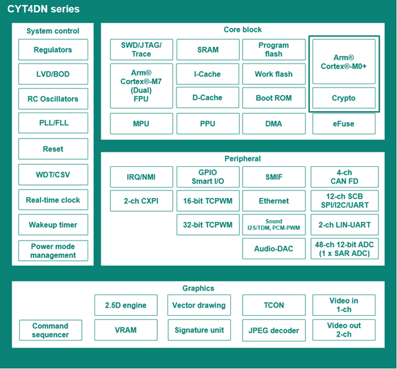
Target applications (CYT4DN series)
Automotive instrument cluster
Head up display (HUD)
Instrument cluster + HUD
Two wheelers
Use cases
Automotive instrument cluster with TRAVEO™ T2G CYT4DN features dual 320 MHz 32-bit Arm® Cortex®-M7 CPUs, up to 6 MB embedded flash memory, 2D/2.5D graphics engine, stepper motor control, sound system, up to 4 CAN FD channels and 10/100/1000 Mbps Ethernet MAC interface. The CYT4DN devices are applied as single-chip solutions to drive a hybrid cluster with traditional gauges and one or two displays. Typically, the second display could be a HUD. The possibility to connect hyper-memories offers another level of scalability between on-chip memory and more expensive external parallel memories. Various sounds such as turn signals, reverse, and alarm sounds are output through speakers. Clusters are connected to in-vehicle networks such as Ethernet AVB, CAN FD, and LIN.