AN240613 Waking up PSOC™ Control C3 MCU from low-power mode
About this document
Scope and purpose
This application note describes the features of low-power modes in the PSOC™ Control C3 MCU family and explains how to enter low-power modes and return to Active mode.
Intended audience
This application note is intended for users who are new to the PSOC™ Control C3 MCU to enable them to use the MCU efficiently to implement solutions using the low-power modes of the microcontroller. In addition to that, this application note briefly explains the different low-power modes available in the MCU.
This application note assumes that you are familiar with PSOC™ Control C3 and the ModusToolbox™ development environment. If you are new to PSOC™ Control C3, see AN238329 - Getting started with PSOC™ Control C3 MCU on ModusToolbox™. If you are new to ModusToolbox™, see the
ModusToolbox™ home page
.
Associated part
family
All PSOC™ Control C3 devices.
Introduction
This application note describes low-power modes in Infineon’s PSOC™ Control C3 family MCUs. This MCU family includes Arm® Cortex® CPU, CAN FD, memory, and analog and digital peripheral functions in a single chip. The PSOC™ Control C3 MCU has several different power modes. These modes are intended to minimize the average power consumption in an application.
This application note explains the features of the power modes and how to set up the power mode transition. To understand the described functionality and terminology used in this application note, see the “Device power modes” chapter of the architecture reference manual for more details.
This application note also introduces system power management library of the
peripheral driver library
(PDL). The PDL is a complete software tool that includes APIs for configuring peripherals and system registers to implement the desired functionality. PDL provides direct access to almost all hardware resources of the target device. It reduces the need to understand and directly access registers and bit structures. PDL is downloaded from GitHub while creating an application in ModusToolbox™ using the Project Creator tool and is not installed along with the ModusToolbox™ IDE.
Power modes of PSOC™ Control C3 MCU
PSOC™ Control C3 MCU has the following power modes:
Active mode
1
: All peripherals and CPU are available. In Active mode, the core voltage can be set to any of the four values. This impacts both power consumption and maximum clock frequency for CPU and peripherals. The following active modes are supported:
Ultra low power (ULP): 0.9 V core voltage with 50 MHz CPU frequency
Medium frequency (MF): 1.0 V core voltage with 70 MHz CPU frequency
Low power (LP): 1.1 V core voltage with 150 MHz CPU frequency
Overdrive (OD): 1.2 V core voltage with 180 MHz CPU frequency
Sleep mode
: All peripherals except the CPU are available
Deep Sleep mode
: Low speed functions are available. The CPU is in retention mode. RAM content is also retained. Only Deep Sleep capable peripherals can wake up the system
Deep Sleep-RAM mode
: The CPU is turned off. Full RAM is retained for a warm boot after wakeup. Only Deep Sleep-capable peripherals are operational if enabled and can wake up the system
Deep Sleep-OFF mode
: Same as Deep Sleep-RAM mode except RAM is also turned off
Hibernate mode
: Device and I/O states are frozen. All peripherals except low-power comparator (LPCOMP) and backup domain peripherals are turned off. All clocks except the backup domain clock and all internal regulators are turned off
shows the relationship between power modes and the power supply current.
Figure 1.
Power modes and power supply current

Note:
Figure 1is only an indication of the power supply currents for each mode. Actual current values depend on the clock configuration and peripheral setting in each mode. For more details on power supply current characteristics, see the datasheet.
Power modes
summarizes the states of each power mode and the entry and wakeup conditions. For more details on power modes, see the architecture reference manual.
Power mode | Description | Entry condition | Wakeup source | Wakeup action |
|---|---|---|---|---|
Active | Primary mode of operation; all peripherals and CPU are available. Current consumption as low as 7 mA (Typ.) | Wake up from sleep, all deep sleep modes, hibernate reset, or any other reset | Not applicable | Not applicable |
Sleep | CPU is in Sleep mode; all other peripherals are available. Current consumption as low as 4 mA (Typ.) | Register write from Active mode or wake up from Deep Sleep through debugger | Any interrupt to CPU | Interrupt |
Deep Sleep | All high-frequency clocks and peripherals are turned off. Low-frequency clock and low-power analog and digital peripherals are available for operation and as wakeup sources. Current consumption as low as 7 μA (Typ.) | Register write from active | GPIO interrupt, low-power comparator (LPCOMP), Deep Sleep serial communication block (SCB), watchdog timer (WDT), real time clock (RTC) alarms, and debugger | Interrupt or debug |
Deep Sleep-RAM | A low-power mode, like Deep Sleep, except most configuration states are not retained. Wake up causes the processors to reboot. The software can use the retained SRAM contents (programmable) to more quickly recover the application state, that is perform a “warm” reboot | Register write from active | GPIO interrupt, Deep Sleep SCB, WDT, RTC alarms | Warm boot |
Deep Sleep-OFF | A low-power mode, like Deep Sleep, except most configuration states and memories are not retained. Wakeup causes the processors to "cold" reboot | Register write from active | GPIO interrupt, Deep Sleep SCB, WDT, RTC alarms | Cold boot (Reset) |
Hibernate | GPIO states are frozen; all high frequency clocks and peripherals are switched off. Low-frequency clocks, and WCO can function. Device resets on wake up event. Current consumption as low as 300 nA (Typ.) | Register write from active | Hibernate WAKEUP pins, LPCOMP, RTC alarm, and WDT | Cold boot (Reset) |
Note:
Before entering Deep Sleep, Deep Sleep-RAM, or Deep Sleep-OFF mode, configures all Power Policy Units (PPUs) to correct states for the difference Deep Sleep mode. See the Power control architecture for the details of PPU.
CPU sleep and wakeup instructions
Arm® Cortex® CPU transitions between sleep and wakeup independently. Wait-for-Interrupt (__WFI) is the core sleep instruction. After a CPU executes __WFI, the CPU goes to sleep and stays in sleep until any interrupt is asserted. Wait-for-Event (__WFE) is similar to __WFI, but it wakes up when the wakeup event is received instead of an interrupt. Set Event (__SEV) is used for waking up other CPUs in sleep mode because of a __WFE. CPU Deep Sleep uses the same instructions for sleep and wakeup, but the SLEEPDEEP bit[2] of the Arm® System Control Register (SCR) is set before a sleep instruction. For more information on SCR, see
Arm® system control register user guide
. This process is implemented in SysPm PDL library, see
System power management (SysPm) library
.
Boot
The boot procedure involves the initialization of various blocks of the PSOC™ Control C3 MCU to get into basic operational mode before entering the application main() function. The boot procedure is invoked on POR, software reset, Deep Sleep-RAM wakeup, Deep Sleep-OFF wakeup, and Hibernate wakeup.
PSOC™ Control C3 MCU supports two types of boot procedures depending on the power mode:
Cold boot: POR, software reset, Deep Sleep-OFF wakeup, and Hibernate wakeup will go through the cold boot procedure
Warm boot: Deep Sleep-RAM wakeup will go through the warm boot procedure
Note:
The boot procedure is not involved when waking up from CPU Sleep and Deep Sleep power modes. The type of boot procedure can be determined using theCy_SysPm_GetBootMode()function of PDL that can be called in the beginning of the main() function so that appropriate action can be taken in the application according to the type of boot executed.
Cold boot
In this boot mode, the system clocks and related clock paths are initialized and then the C runtime environment is set up before entering the main () function. For Deep Sleep-OFF and Hibernate wakeup, the device resets everything except the backup power domain resources. There is a small difference for initial power ON where even the backup power domain is reset.
Warm boot
Waking up from Deep Sleep-RAM mode results in a warm boot procedure. Warm boot is a shortened version of the complete boot process. The application can specify an entry point for warm boot, which is the starting point of execution for the CPU upon waking up from Deep Sleep-RAM. This results in shortened boot procedure execution time.
This is done using the
Cy_Syslib_SetWarmBootEntryPoint()
function of PDL. Using this function, an entry point such as a function address can be specified along with the stack pointer value that needs to be restored. See
Implementing low-power mode transitions
section. This feature enables you to implement a variety of use cases such as the device can enter the Deep Sleep-RAM state after setting an RTC alarm interrupt, GPIO or WDT interrupt. When the interrupt is triggered, the device wakes up from Deep Sleep-RAM, the CPU executes the warm boot procedure, and the control is transferred to the entry point function.
Power control architecture
PSOC™ Control C3 MCU uses the Arm® power control architecture. The components used to control a single power domain are shown in following figure. For more information, see
Arm® power control architecture
.
Figure 2.
Power gating in power control architecture
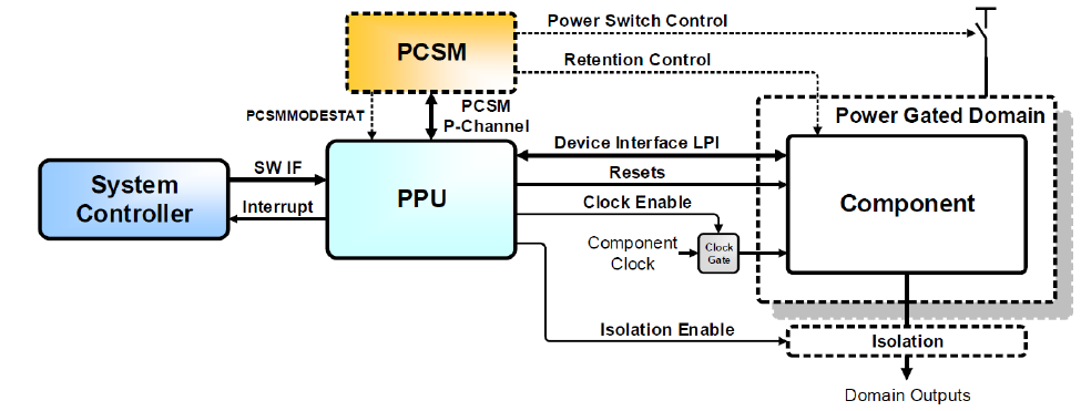
Power Policy Unit (PPU)
: Usually controls the power domain, but it can also be used to implement separate reset domains within a single power domain. The "SW IF" is the software interface from the system controller (for example, M33 processor). It is an Advanced Peripheral Bus (APB) interface at the PPU, and it is mapped to the Advanced High-performance Bus (AHB) memory-mapped I/O (MMIO) through an asynchronous bus bridge. The device interface labeled “LPI” stands for Low Power Interface, which is usually implemented as a Q- or P-channel
Power Control State Machine (PCSM)
: A custom hardware module that controls the power switches. System Controller refers to an MCU (for example, M33). For the specific use case where the main active PPU that controls VCCACT_PD, the system controller is inside the power-gated domain. For this, the software interface (SW IF) and interrupt signals are isolated as required
Additionally, there is a custom component called Power Dependency Control Matrix (PDCM) that is present in Arm® reference design. All PPUs interface with the PDCM, which handles dependency relationships between power domains.
Power states supported by each PPU
PSOC™ Control C3 MCU has three PPUs. See
Table 2
and
Table 3
for more information.
PPU | PPU state |
|---|---|
PPU_MAIN | ON |
FULL_RETENTION | |
MEMORY_RETENTION | |
OFF | |
PPU_CPUSS | ON |
FULL_RETENTION | |
OFF | |
PPU_SRAM | ON |
MEMORY_RETENTION | |
OFF |
Deep Sleep state | PPU power modes |
|---|---|
Deep Sleep | PPU_MAIN: FULL_RETENTION |
PPU_CPUSS: FULL_RETENTION | |
PPU_SRAM: MEMORY_RETENTION | |
Deep Sleep-RAM | PPU_MAIN: MEMORY_RETENTION |
PPU_CPUSS: OFF | |
PPU_SRAM: MEMORY_RETENTION | |
Deep Sleep-OFF | PPU_MAIN: OFF |
PPU_CPUSS: OFF | |
PPU_SRAM: OFF |
The PDL implements the
Cy_SysPm_SetDeepSleepMode()
function to set the different Deep Sleep mode by configuring three PPUs. See the
Implementing low-power mode transitions
section.
Power modes transition
shows the different states that the device can be in along with the possible power mode transition paths. The transitions are described in detail in subsequent sections of this document.
Figure 3.
Power mode transitions

RESET/OFF state
OFF state
Represents the state with no power applied
Go to RESET, when powered up above power-on reset level (POR event)
RESET state
Detected reset event: POR, External Reset (XRES), or Internal Reset
Go to Active mode after reset sequence completion
Device will enter RESET state upon assertion of XRES in any of the power modes
Entering low power mode
shows how to enter low-power mode and the actions in low power modes.
Initial mode | Final mode | Trigger | Hardware actions |
|---|---|---|---|
Active | Sleep | Firmware action
Tip: PDL provides API to implement the above steps, see System power management (SysPm) library chapter for more details. |
|
Active | Deep Sleep | Firmware action Perform these steps to enter Deep Sleep mode (LPM_READY bit [5] of the PWR_CTL register should read ‘1’ before performing these steps):
Tip: PDL provides and APIs to configure PPUs and enter into Deep Sleep mode, see System power management (SysPm) library section for more details. |
|
Active | Deep Sleep-RAM | Firmware action Perform these steps to enter Deep Sleep mode (LPM_READY bit [5] of the PWR_CTL register should read ‘1’ before performing these steps):
Tip: PDL provides and APIs to configure PPUs and enter into Deep Sleep-RAM mode, see System power management (SysPm) library section for more details. |
|
Active | Deep Sleep-OFF | Firmware action Perform these steps to enter Deep Sleep mode (LPM_READY bit [5] of the PWR_CTL register should read ‘1’ before performing these steps):
Tip: PDL provides and APIs to configure PPUs and enter into Deep Sleep-OFF mode, see System power management (SysPm) library section for more details. |
|
Active | Hibernate | Firmware action
Tip: PDL provides and APIs to set wakeup source and implement the above steps to enter Hibernate mode, see System power management (SysPm) library section for more details. Note: It is recommended to trigger Hibernate mode automatically. Therefore, when entering Hibernate mode, disable all the interrupts and do a write operation on the PWR_Hibernate register. |
|
Sleep | Deep Sleep | When the debugger is not connected and Deep Sleep mode is triggered, but LPM_READY==0, the device internally enters Sleep mode. The device will automatically transit to Deep Sleep when LPM_READY == 1. If the debugger is connected and Deep Sleep mode is triggered by the firmware, the device will enter Deep Sleep only when the following conditions are met:
|
|
shows the software and hardware operation for the transition from Active mode to Deep Sleep mode.
Figure 4.
Active mode to Deep Sleep mode transition

Note:
InFigure 4andFigure 5, the gray boxes indicate hardware operation. Therefore, processing with software is not required.
shows the software and hardware operation for the transition from Active mode to Hibernate mode.
Figure 5.
Active mode to Hibernate mode transition

Waking up from low power modes
shows the hardware triggers for wakeup and the actions after wakeup.
Initial mode | Final mode | Trigger source | Hardware action |
|---|---|---|---|
Sleep | Active | Any enabled interrupt in Sleep mode | CPU exits Sleep mode and executes the interrupt |
Deep Sleep | Active | Any enabled interrupt in Deep Sleep mode | The device returns to the configuration it had while entering Deep Sleep mode. (Active reference and core regulator turn on; IMO/clocks enabled, retention disabled, non-retained resets, freeze release; CPU exits low-power mode and takes interrupt) |
Deep Sleep | Sleep | Debug wakeup |
|
Deep Sleep-RAM | Active | Any enabled interrupt in Deep Sleep mode | The device executes warm boot. (Active reference and core regulator turn on; IMO/clocks enabled, retention and non-retained resets, freeze release; high frequency clocks turn on, FLL/PLL enable) |
Deep Sleep-OFF | Active | Any enabled interrupt in Deep Sleep mode | The device resets (cold boot). (Active reference and core regulator turn on; IMO/clocks enabled, retention and non-retained resets, freeze release; high frequency clocks turn on, FLL/PLL enable) |
Hibernate | Active | Hibernate wakeup pins, RTC alarms, LPCOMP, WDT | Hibernate wakeup is implemented as a transition to Active mode through reset:
|
shows the software and hardware operation for the transition from Deep Sleep mode to Active mode.
Figure 6.
Deep Sleep mode to Active mode transition

Note:
The gray boxes indicate hardware operation inFigure 6. Therefore, processing with software is not required.
System power management (SysPm) library
Within the PDL, the system power management (SysPm) API provides functions to change power modes as shown in
Figure 3
. The API can also register callback functions to execute a peripheral function before or after power mode transitions. For more information, see
SysPM documentation
of the PDL.
Mode transition functions
The system can enter the Sleep, Deep Sleep, Deep Sleep-RAM, Deep Sleep-OFF, and Hibernate modes using the PDL APIs.
Table 6
lists some PDL APIs to configure the different power modes.
API | Description |
|---|---|
| Sets executing CPU to Sleep mode |
| Sets the Deep Sleep mode: Deep Sleep or Deep Sleep-RAM or Deep Sleep-OFF |
| Sets executing CPU to the Deep Sleep mode |
| Configures sources to wake up the device from the system Hibernate power mode |
| Sets the device into system Hibernate mode |
The SysPm PDL driver manages low-power callbacks registered by the application. When a power mode transition is about to occur, the driver calls the registered callbacks to allow the application to prepare for the transition. This may involve disabling peripherals or ensuring that no data is being transmitted or received.
To enable this, the SysPm driver implements a callback mechanism. When a lower power mode transition is about to take place (either entering or exiting low-power modes), the registered callbacks for that transition are called. Every callback function should handle the five possible steps shown in
Table 7
.
Callback function option | Description |
|---|---|
| Checks the ready state to transition to other mode. Exits without transition if it returns |
| Callbacks execute and configure required actions before mode transition |
| Callbacks execute after mode transition or configuration |
| Callbacks execute only when |
| Performs the actions to be done after exiting Deep Sleep if entered and before interrupts are enabled |
A callback function can skip some steps.
Table 8
outlines the available skip options.
Callback function skip option | Description |
|---|---|
| Define to skip check ready mode in the SysPm callback |
| Define to skip check fail mode in the SysPm callback |
| Define to skip before transition mode in the SysPm callback |
| Define to skip after transition mode in the SysPm callback |
The SysPm driver organizes all the callbacks into a linked list. While entering a low-power mode, SysPm goes through that linked list from first to last, executing the callbacks one after another. While exiting low-power mode, SysPm goes through that linked list again, but in the opposite direction from last to first. This ordering supports prioritization of callbacks relative to the transition event.
By calling the mode transition function, the device starts to transition with five callback operations. The CPU Sleep and CPU Deep Sleep modes use Arm® sleep instructions __WFI() or __WFE(). Code execution stops and waits for an interrupt during the CPU Sleep mode. After waking up from Sleep mode, the device automatically transitions to CPU Active.
Figure 7.
Sleep/Deep Sleep/Hibernate mode transition

Implementing low-power mode transitions
Use the System Power Management (SysPm) driver to change power modes and reduce system power consumption in power sensitive designs. The functions and other declarations used in this driver are in
cy_syspm.h
. You can include
cy_pdl.h
to get access to all functions and declarations in the PDL.
Switching the CPU into Sleep mode
The
Cy_SysPm_CpuEnterSleep()
function switches the calling CPU into the CPU Sleep power mode. You must clear all pending interrupts before putting the CPU into Sleep mode, even if they are masked.
/* Prepare the system for CPU Sleep mode here.
 * This may include clearing pending interrupts,
 * disabling peripherals, and saving necessary states.
 */

if (CY_SYSPM_SUCCESS != Cy_SysPm_CpuEnterSleep(CY_SYSPM_WAIT_FOR_INTERRUPT))
{
  /* Error: System failed to enter CPU Sleep mode.
  A registered CPU Sleep "check ready" callback returned an error status.*/
}
else
{
  /* System successfully exited CPU Sleep mode.
  The program has resumed execution after waking up from CPU Sleep.*/
}
Switching the MCU into Deep Sleep mode
The
Cy_SysPm_CpuEnterDeepSleep()
function switches the CPU into Deep Sleep power mode. The following code snippet demonstrates how to configure the system to enter Deep Sleep mode, showcasing the necessary steps to achieve System Deep Sleep state.
int main(void)
{
  ...

  /* Deep Sleep mode configuration */
  Cy_SysPm_SetDeepSleepMode(CY_SYSPM_MODE_DEEPSLEEP);

  for (;;)
  {
    /* Wait for UART traffic to stop */
    while (cy_retarget_io_is_tx_active()) {};

    if (CY_SYSPM_SUCCESS != Cy_SysPm_CpuEnterDeepSleep(CY_SYSPM_WAIT_FOR_INTERRUPT))
    {
      /* Error: System failed to enter CPU Deep Sleep mode.
         A registered CPU Deep Sleep "check ready" callback returned an error status.*/
    }
    else
    {
      /* System successfully exited CPU Deep Sleep mode.
      The program has resumed execution after waking up from CPU Sleep.*/
    }
  }
}
Switching the MCU into Deep Sleep-RAM mode
Before the
Cy_SysPm_CpuEnterDeepSleep()
function switches the CPU into Deep Sleep-RAM power mode, the following steps need to performed:
The warm boot entry point is set by using the
Cy_Syslib_SetWarmBootEntryPoint()
function. This is automatically taken care as part of auto-generated code inside the
cybsp_init()
. To know more about warm boot entry, see
Warm boot
Register the Deep Sleep-RAM callback to store NVIC registers to the RAM by using the
System_Store_NVIC_Reg()
function to ensure that the NVIC register data is persistent after the device wakes up from Deep Sleep-RAM
Set Deep Sleep mode to Deep Sleep-RAM power mode by calling the
Cy_SysPm_SetDeepSleepMode()
function
After wake up from Deep Sleep-RAM mode, the warm boot entry point handler
cybsp_warmboot_handler()
is performed. In the
cybsp_warmboot_handler()
function, the
SystemInit_Warmboot_CAT1B_CM33()
function is called to enable all peripheral blocks through the peripheral control registers and unfreeze all the I/Os, initialize the device and board peripherals, and execute the after-transition callback to restore the NVIC data from the RAM by using the
System_Restore_NVIC_Reg()
function, then jump to
main()
.
The following code snippet demonstrates how to configure the system to enter Deep Sleep-RAM mode and wake up from this mode, showcasing the necessary steps to achieve Deep Sleep-RAM state and wakeup.
/* Function prototypes */
cy_en_syspm_status_t deepsleep_ram_callback_func(cy_stc_syspm_callback_params_t*callbackParams, cy_en_syspm_callback_mode_t mode);
int main(void);

/* Callback declaration for Deep Sleep-RAM */
cy_stc_syspm_callback_params_t deepsleep_ram_callback_param = {NULL, NULL};
cy_stc_syspm_callback_t deepsleep_ram_callback =
{
  .callback = &deepsleep_ram_callback_func,
  .type = CY_SYSPM_DEEPSLEEP_RAM,
  .callbackParams = &deepsleep_ram_callback_param,
  .order = 0u
};

/* The variable of boot mode */
CY_NOINIT cy_en_syspm_boot_mode_t boot_mode;

/* This function is called before entering main() */
void Cy_SystemInit(void)
{
  /* Gets from which Deep Sleep mode the device has woke up */
  boot_mode = Cy_SysPm_GetBootMode();
}

/* This function is called in cybsp_warmboot_handler(), and jump to main() */
void cybsp_syspm_do_warmboot(void)
{
  /* Execute DeepSleep-RAM callback function after the device has woke up */
  (void)Cy_SysPm_ExecuteCallback(CY_SYSPM_DEEPSLEEP_RAM, CY_SYSPM_AFTER_TRANSITION);

  /* Desired resume point of the application */
  (void)main();
}

/* GPIO interrupt handler */
void user_button_intr_handler(void)
{
  Cy_GPIO_ClearInterrupt(CYBSP_USER_BTN_PORT, CYBSP_USER_BTN_PIN);
}

int main(void)
{
  cy_rslt_t result;

  /* Checks if system woke up(From DeepSleep-RAM) through warm boot */
  if(Cy_SysLib_IsDSRAMWarmBootEntry())
  {
    /* Free the required peripherals after waking-up from DS-RAM */
    cy_retarget_io_deinit();
  }
  else
  {
    /* Initialize the device and board peripherals */
    result = cybsp_init();
    /* Board init failed. Stop program execution */
    if (result != CY_RSLT_SUCCESS)
    {
      CY_ASSERT(0);
    }
  }

  /* Initialize UART and retarget-io to use the debug UART port */
  ...

  /*Enable wake up interrupt, for example: initialize GPIO interrupt and enable IRQ */
  cy_stc_sysint_t user_button_intr_config =
  {
    .intrSrc = CYBSP_USER_BTN_IRQ,
    .intrPriority = 0U,
  };
  Cy_SysInt_Init(&user_button_intr_config, user_button_intr_handler);
  NVIC_EnableIRQ(user_button_intr_config.intrSrc);

  if(CY_SYSPM_WARM_BOOT_MODE == boot_mode)
  {
    /* Warm boot (wake up form Deep Sleep-RAM mode */
  }
  else if(CY_SYSPM_POR_BOOT_MODE == boot_mode)
  {
    /* POR boot */
  }

  /* Check the Warm Boot entry Status flag */
  if(!Cy_SysLib_IsDSRAMWarmBootEntry())
  {
    /* When POR, register the Deep Sleep-RAM callback function */
    if (!Cy_SysPm_RegisterCallback(&deepsleep_ram_callback))
    {
      CY_ASSERT(0);
    }
  }
  else /* The device woke up(From Deep Sleep-RAM) through warm boot */
  {
    /* Clears the Warm Boot entry Status flag */
    Cy_SysLib_ClearDSRAMWarmBootEntryStatus();
  }

  /* Set Deep Sleep mode to Deep Sleep-RAM */
  Cy_SysPm_SetDeepSleepMode(CY_SYSPM_MODE_DEEPSLEEP_RAM);

  /* Enable global interrupts */
  __enable_irq();

  for (;;)
  {
    /* Wait for UART traffic to stop */
    while (cy_retarget_io_is_tx_active()) {};

    if(CY_SYSPM_SUCCESS != Cy_SysPm_CpuEnterDeepSleep(CY_SYSPM_WAIT_FOR_INTERRUPT))
    {
      /* Error: System failed to enter CPU Deep Sleep-RAM mode.
         A registered Deep Sleep-RAM "check ready" callback returned an error status.*/
    }
    else
    {
      /* CY_SYSPM_SUCCESS is never seen here as successfully entering
       * Deep Sleep-RAM mode. This is because a wake up from
       * Deep Sleep-RAM mode goes through the warm boot. */
    }
  }
}

cy_en_syspm_status_t deepsleep_ram_callback_func(cy_stc_syspm_callback_params_t*callbackParams, cy_en_syspm_callback_mode_t mode)
{
  cy_en_syspm_status_t retVal = CY_SYSPM_FAIL;
  CY_UNUSED_PARAMETER(callbackParams);

  switch (mode)
  {
    case CY_SYSPM_CHECK_READY:
      retVal = CY_SYSPM_SUCCESS;
      break;

    case CY_SYSPM_CHECK_FAIL:
      retVal = CY_SYSPM_SUCCESS;
      break;

    case CY_SYSPM_BEFORE_TRANSITION:
      /* Store NVIC registers to the RAM */
      System_Store_NVIC_Reg();
      retVal = CY_SYSPM_SUCCESS;
      break;

    case CY_SYSPM_AFTER_DS_WFI_TRANSITION:
      /* Restore the NVIC data from the RAM */
      System_Restore_NVIC_Reg();
      retVal = CY_SYSPM_SUCCESS;
      break;

    case CY_SYSPM_AFTER_TRANSITION:
      retVal = CY_SYSPM_SUCCESS;
      break;

    default:
      break;
  }
  return retVal;
}
Switching the MCU into Deep Sleep-OFF mode
Before the
Cy_SysPm_CpuEnterDeepSleep()
function switches the CPU into Deep Sleep-OFF power mode, set Deep Sleep mode to Deep Sleep-OFF power mode by calling the
Cy_SysPm_SetDeepSleepMode()
function. The following code snippet demonstrates how to configure the system to enter Deep Sleep-OFF mode, showcasing the steps necessary to achieve Deep Sleep-OFF state.
/* The variable of boot mode */
CY_NOINIT cy_en_syspm_boot_mode_t boot_mode;

/* This function is called before entering main */
void Cy_SystemInit(void)
{
  /* Checks from which Deep Sleep mode the system has woke up */
  boot_mode = Cy_SysPm_GetBootMode();

  /* Checks whether IOs are frozen during DEEPSLEEP-RAM/OFF */
  if (Cy_SysPm_DeepSleepIoIsFrozen())
  {
    Cy_SysPm_DeepSleepIoUnfreeze();
  }
}

/* GPIO interrupt handler */
void user_button_intr_handler(void)
{
  Cy_GPIO_ClearInterrupt(CYBSP_USER_BTN_PORT, CYBSP_USER_BTN_PIN);
}

int main(void)
{
  ...
  /*Enable wake up interrupt, for example: initialize GPIO interrupt and enable IRQ */
  cy_stc_sysint_t user_button_intr_config =
  {
    .intrSrc = CYBSP_USER_BTN_IRQ,
    .intrPriority = 0U,
  };
  Cy_SysInt_Init(&user_button_intr_config, user_button_intr_handler);
  NVIC_EnableIRQ(user_button_intr_config.intrSrc);

  if(CY_SYSPM_COLD_BOOT_MODE == boot_mode)
  {
    /* Cold boot (wake up form Deep Sleep-OFF mode */
  }
  else if(CY_SYSPM_POR_BOOT_MODE == boot_mode)
  {
    /* POR boot */
  }

  /* Update boot entry point before entering Deep Sleep-OFF mode */
  SRSS_BOOT_ENTRY = CY_FLASH_S_CBUS_BASE;

  /* Set Deep Sleep mode to Deep Sleep-OFF */
  Cy_SysPm_SetDeepSleepMode(CY_SYSPM_MODE_DEEPSLEEP_OFF);

  /* Enable global interrupts */
  __enable_irq();

  for (;;)
  {
    /* Wait for UART traffic to stop */
    while (cy_retarget_io_is_tx_active()) {};

    if (CY_SYSPM_SUCCESS != Cy_SysPm_CpuEnterDeepSleep(CY_SYSPM_WAIT_FOR_INTERRUPT))
    {
       /* Error: System failed to enter CPU Deep Sleep-OFF mode.
          A registered Deep Sleep-OFF "check ready" callback returned an error status.*/
    }
    else
    {
      /* CY_SYSPM_SUCCESS is never seen here as successfully
       * entering Deep Sleep-OFF mode. This is because a wake up
       * from Deep Sleep-OFF mode goes through the cold boot. */
    }
  }
}
Switching the MCU to Hibernate mode
If you call the
Cy_SysPm_SystemEnterHibernate
function, the system will be switched into the Hibernate power mode directly.
int main(void)
{
  ...

  uint32_t reset_reason;

  /* Check the IO status. If current status is frozen, unfreeze the system. */
  if (Cy_SysPm_GetIoFreezeStatus())
  {
    /* Unfreeze the system */
    Cy_SysPm_IoUnfreeze();
  }

  /* Get the reset cause */
  reset_reason = Cy_SysLib_GetResetReason();

  if ((reset_reason & CY_SYSLIB_RESET_HIB_WAKEUP))
  {
    /* The reset has occurred on a wakeup from Hibernate power mode */
  }

  /* Enable global interrupts */
  __enable_irq();

  for (;;)
  {
    Cy_SysPm_ClearHibernateWakeupSource(CY_SYSPM_HIBERNATE_PIN0_LOW);

    /* There is a need to put the device into the system Hibernate modeSetup the
     * Hibernate wakeup source.*/
    Cy_SysPm_SetHibernateWakeupSource(CY_SYSPM_HIBERNATE_PIN0_LOW);

    /* Prepare the device for system Hibernate mode here */
    if (CY_SYSPM_SUCCESS != Cy_SysPm_SystemEnterHibernate())
    {
      /* System did not enter Hibernate mode because a registered
       * Hibernate "check ready" callback returned a "not success" status */
    }
    else
    {
      /* CY_SYSPM_SUCCESS is never seen here as successfully entering
       * system Hibernate mode. This is because a wake up from
       * system Hibernate mode goes through the system reset. */
    }
  }
}
The system can wake up from Hibernate mode by configuring the following wakeup sources: GPIO Wakeup pin, LPCOMP, RTC alarm, WDT.
A device-specific pin or pins with programmable polarity can wake up the system. Additionally, certain unregulated peripherals can trigger wakeup under specific conditions. For instance, a low-power comparator can wake the system by comparing two external voltages or compare an external voltage to an internally generated voltage. The Watchdog Timer (WDT) can also be configured to wake up the system by generating a WDT interrupt.
Note:
When booting from Hibernate mode, call theCy_SysPm_IoUnfreeze()function to unfreeze the GPIOs, which are frozen when the device enters System Hibernate mode.
Register callback functions using PDL
The following code snippet showcases how to register the SysPm callbacks.
/******************************************************************************
 *  Callback prototypes
 ******************************************************************************/
cy_en_syspm_status_t DeepSleepCallback(cy_stc_syspm_callback_params_t *callbackParams, cy_en_syspm_callback_mode_t mode);

/******************************************************************************
 *  Parameter structures for callback functions
 ******************************************************************************/
cy_stc_syspm_callback_params_t DeepSleepCallbackParams =
{
  &HW1_address,
  &context
};

/******************************************************************************
 *  Callback structure
 ******************************************************************************/
cy_stc_syspm_callback_t myDeepSleep =
{
  &DeepSleepCallback,
  CY_SYSPM_DEEPSLEEP,
  CY_SYSPM_SKIP_BEFORE_TRANSITION,
  &DeepSleepCallbackParams,
  NULL,
  NULL,
  0
};

/******************************************************************************
 *  Register DeepSleepCallback
 ******************************************************************************/
if (true != Cy_SysPm_RegisterCallback( &myDeepSleep)
{
  /* Insert error handling */
}
Implementing custom callback functions using PDL
In the SysPm callback, you can define the actions to be performed before and after the power mode transition.
/******************************************************************************
 * * DeepSleepCallback implementation
 * ******************************************************************************/
cy_en_syspm_status_t DeepSleepCallback(cy_stc_syspm_callback_params_t *callbackParams, cy_en_syspm_callback_mode_t mode)
{
  cy_en_syspm_status_t retVal = CY_SYSPM_FAIL;
  if (NULL != callbackParams)
  {
    CySCB_Type *hwBase = (CySCB_Type *)callbackParams->base;
    cy_stc_scb_spi_context_t *context = (cy_stc_scb_spi_context_t *)callbackParams->context;
  }
  switch (mode)
  {
    /* In this case ensure that firmware/hardware is ready for CPU Deep Sleep mode */
    case CY_SYSPM_CHECK_READY:
    { /* Process the "check ready" condition */
      retVal = CY_SYSPM_SUCCESS;
    }
    break;

    /* One of the registered callback returned CY_SYSPM_FAIL, need to
      revert changes (if any) performed in the CY_SYSPM_CHECK_READY case. */
    case CY_SYSPM_CHECK_FAIL:
    { /* Revert changes done in the CY_SYSPM_CHECK_READY case */
      retVal = CY_SYSPM_SUCCESS;
    }
    break;

    /* This case will be skipped during callbacks execution */
    case CY_SYSPM_BEFORE_TRANSITION:
    break;

    /* This case is executed after wakeup from system Deep Sleep */
    case CY_SYSPM_AFTER_TRANSITION:
    { /* Perform actions, if required, after wakeup from the system Deep Sleep
         mode */
      retVal = CY_SYSPM_SUCCESS;
    }
    break;

   default:
    break;
  }
return(retVal);
}
Low power code examples
This chapter lists the code examples that describe how to use the low power procedure using the
Peripheral Driver Library
(PDL).
CE239867 – Hibernate GPIO wakeup
This code example demonstrates the use of Hibernate mode and wakeup from GPIO (Hibernate wakeup pin) using the PDL functions.
The example sets pin P2.0 to low level to wake up the MCU before the MCU enters the Hibernate mode. When P2.0 is low level, wake up MCU from Hibernate mode, then the reset reason message is sent on the UART terminal. For more information of the code example, see
CE239867 – Hibernate GPIO wake up
.
CE240527 – RTC alarm periodic wakeup
This code example demonstrates how to enter Deep Sleep and Hibernate modes, and use RTC to generate an RTC alarm to wake up the MCU from these modes.
The MCU enters either Deep Sleep or Hibernate mode based on the duration that the user button is pressed. The RTC alarm wakes up the system and prints the wakeup information to the UART terminal. The following figure shows the state machine implemented in the firmware to execute the transitions. For more information, see
CE240527 – PDL RTC alarm periodic wake up
.
Figure 8.
RTC periodic wakeup timer using alarm interrupt

CE240257 – Wake up from Deep Sleep/Hibernate mode using a low-power comparator
This code example demonstrates the functionality of wake up from Deep Sleep or Hibernate mode using the low-power comparator (LPCOMP). It uses a dedicated GPIO input to compare the input voltage to an internal reference voltage to wake the PSOC™ Control C3 MCU from Deep Sleep or Hibernate mode. A user LED indicates the current power mode.
The following figure shows the firmware flow. The main loop checks the output of LPCOMP and toggles the LED when the output is high. Otherwise, the system goes into the Deep Sleep or Hibernate mode after turning the LED ON for two seconds. The system will wake up immediately if the LPCOMP output goes high during Deep Sleep or Hibernate mode. For more information of code example, see
CE240257 - Wakeup from DeepSleep/Hibernate mode using a low-power comparator
.
Figure 9.
Wake up from Deep Sleep/Hibernate mode using a low-power comparator

CE240361 – I2C slave Deep Sleep wakeup
This code example demonstrates the operation of the I2C resource in Deep Sleep mode. After programming, the application starts automatically. The UART terminal displays the slave initialization and the MCU entering Deep Sleep mode. Using the Bridge Control Panel (BCP) software to transmit and receive the data over I2C, BCP is installed automatically as part of the
PSOC™ Programmer
installation. Send the command to wake the device up from Deep Sleep and display a wake up message on the terminal.
The I2C driver provides callback function
Cy_SCB_I2C_DeepSleepCallback()
to handle power mode transition. It calls the
Cy_SysPm_RegisterCallback()
function to register I2C Deep Sleep callback in initialization of main. For more information of the code example, see
CE240361 – I2C slave Deep Sleep wake up
.
Summary
shows available resources which are active in certain power modes and its wakeup parameters.
Active/Sleep | Deep Sleep | Deep Sleep-RAM | Deep Sleep-OFF | Hibernate | Off | |
|---|---|---|---|---|---|---|
Parameters | ||||||
Wake source 2 | Any interrupt | Deep Sleep peripherals | Deep Sleep peripherals | Deep Sleep peripherals | RTC/Hibernate peripherals | Power on |
Wake action | Resume | Resume | Warm boot | Reset/cold boot | Reset | Reset |
Wake time | One CPU cycle | < 20 µs | Deep Sleep + warm boot | Deep Sleep + cold boot | POR + cold boot < 1 ms | |
Resources | ||||||
ECO | On/Off | Off | Off | Off | Off | Off |
IHO | On | Off | Off | Off | Off | Off |
IMO | On | On/Off | Off | Off | Off | Off |
ILO | On/Off | On/Off | On/Off | On/Off | On/Off | Off |
WCO | On/Off | On/Off | On/Off | On/Off | On/Off | Off |
CPU | On/Sleep | Retention | Off | Off | Off | Off |
SRAM | On | On | On/Off | Off | Off | Off |
The operational states possible in low-power modes are generally limited in functionality and parametric performance as compared to their capabilities in the Active modes. Also, blocks that do not support low-power modes, such as Deep Sleep and Hibernate, cannot wake up the CPU from these modes.
captures various device components and their availability during the device power modes/states.
Block | Power mode | ||||
|---|---|---|---|---|---|
Active | Sleep | Deep Sleep | Hibernate | Backup | |
CPUSS | |||||
CPU | Y | N | N | N | N |
NVIC | Y | Y | N | N | N |
WIC | Y | Y | Y | Y | N |
FLASH | Y | Y | N | N | N |
SRAM | Y | Y | Y | N | N |
DMA | Y | Y | N | N | N |
Programmable digital | |||||
SMART I/O | Y | Y | Y | N | N |
Fixed function digital | |||||
TCPWM | Y | Y | N | N | N |
SCB | Y | Y | Y 3 | N | N |
CAN FD™ | Y | Y | N | N | N |
Special function | |||||
CORDIC | Y | N | N | N | N |
Analog | |||||
HPPASS (SAR, CSG) | Y | Y | N | N | N |
LPCOMP | Y | Y | Y 4 | Y | N |
I/O | |||||
GPIO | Y | Y | Y | Y 5 | N |
Backup | |||||
RTC | Y | Y | Y | Y | Y |
Registers | Y | Y | Y | Y | Y |
References
The datasheets and references manuals of
family are listed here.
Contact
Technical Support
to obtain these documents.
Datasheets
PSOC™ Control C3 - PSC3P5xD, PSC3M5xD datasheet
PSOC™ Control C3 - PSC3P2xD, PSC3M3xD datasheet
Reference manuals
PSOC™ Control C3 MCU architecture reference manual
PSOC™ Control C3 MCU registers reference manual
Application notes and user guides
AN238329 - Getting started with PSOC™ Control C3 MCU on ModusToolbox™ software
PSOC™ Control C3 MCU hardware design guide
KIT_PSC3M5_EVK PSOC™ Control C3 Evaluation Kit guide
Revision history
Document revision | Date | Description of changes |
|---|---|---|
** | 2024-11-29 | Initial release |
1
The core voltage can be configured in Device Configurator of ModusToolbox™. It will be automatically configured in the auto-generated code inside the
cybsp_init()
.
3
Only SCB 0 (I2C, SPI)
4
Cannot wake up from Deep Sleep-RAM and Deep Sleep-OFF mode using LPCOMP.
5
Only hibernate_wakeup pins (P2.0 and P9.0) are operational and capable of waking up the device from Hibernate mode. For more information, see the datasheet.